Boeing 737 - 600/700/800/900. Operations Manual (1997 year) - page 47
Flight Instruments, Displays -
Head-Up Display System -
Displays
Boeing 737 Operations Manual
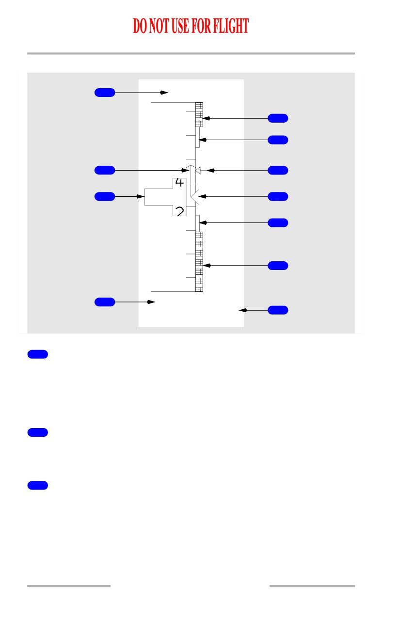
Airspeed Indications - General
1
213
240
4
5
220
2
6
3
2
0
3
3
7
180
8
10
.415
GS
9
185
1
Selected Speed (all modes)
Displays target airspeed:
• manually selected in the IAS/MACH window
• indicates the FMC computed airspeed when the IAS/MACH window is
blank.
2
Speed Trend Vector (PRI in flight, PRI ground modes)
Tip of arrow indicates predicted airspeed in the next 10 seconds based on the
current airspeed and acceleration.
3
Computed Airspeed (PRI in flight, PRI ground modes)
Indicates current computed airspeed in knots.
Displayed relative to a vertical scale along the edge of the tape and as a digital
value.
10.12.4
Flight Instruments, Displays -
Head-Up Display System -
Displays
Boeing 737 Operations Manual
4
Maximum Speed (PRI in flight mode)
Bottom of bar indicates the maximum speed as limited by the lowest of the
following:
• Vmo/Mmo
• landing gear placard speed
• flap placard speed.
Inhibited on the ground.
5
Maximum Maneuvering Speed (PRI in flight mode)
At high altitudes and flaps up, the bottom of the bar indicates the airspeed that
provides a 0.3 g maneuver margin to high speed buffet. May be displayed at high
altitude with flaps up, at relatively high gross weights.
When flaps are not up, bottom of the bar indicates flap limit placard speed for the
next normal flap setting. The display logic is based on a normal flap setting
sequence of 1, 5, 15, 30. The bar is removed when the flap lever is moved to the
landing flap selected on the APPROACH REF page or when the flap lever is
moved to flaps 30 or 40.
6
Speed Bug (PRI in flight, PRI ground modes)
Points to the airspeed:
• manually selected in the IAS/MACH window
• indicates the FMC computed airspeed when the IAS/MACH window is
blank.
When the selected speed is off scale, the bug is parked at the top or bottom of the
tape, with only one half bug visible.
7
Minimum Maneuver Speed (PRI in flight, PRI ground modes)
Top of bar indicates minimum maneuver speed.
8
Minimum Speed (PRI in flight mode)
Top of bar indicates the speed at which stick shaker occurs.
Inhibited on the ground.
9
Ground Speed (all modes)
Indicates current ground speed in one knot increments.
10.12.5
Flight Instruments, Displays -
Head-Up Display System -
Displays
Boeing 737 Operations Manual
10
Mach Speed (PRI in flight)
Indicates current mach speed when mach increases above .400 and removed when
mach decreases below .380.
Note: In other than the PRI mode, the airspeed scale and associated symbols are
replace with a digital readout. The readout is positioned relative to the
flight path vector. If the flight path vector is not displayed, the readout is
positioned relative to the airplane reference symbol.
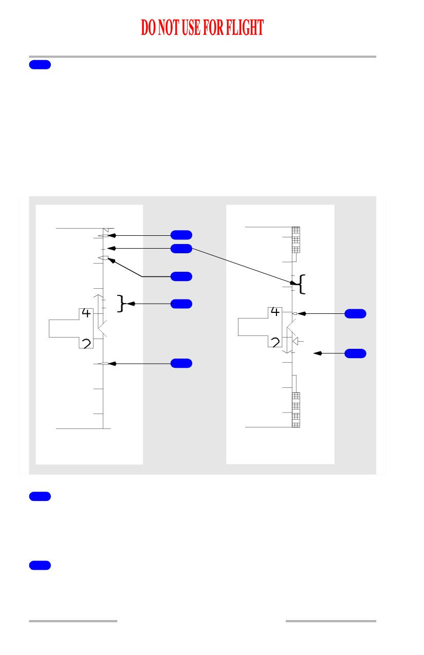
Airspeed Indications - Takeoff and Approach
[Option - 100 knot airspeed bug]
213
138
150
1
180
1
2
3
5
130
160
15
VR
4
V1
5
1
1
3
1
4
3
REF
6
7
90
120
GS
GS
100
135
1
Bug 5 (PRI in flight, PRI ground modes)
Displayed if speed reference selector on the engine display control panel is in the
bug 5 position or SET position and a value greater than 60 knots has been selected.
Not available if the speed reference selector is in the AUTO position.
2
Flaps Maneuvering Speeds (PRI in flight mode)
Indicates flap maneuvering speed for the displayed flap position.
10.12.6
Flight Instruments, Displays -
Head-Up Display System -
Displays
Boeing 737 Operations Manual
3
V2+15 (PRI in flight mode)
Displayed for takeoff.
Removed when either of the following occurs:
• at first flap retraction
• when VREF is entered in the CDU.
4
Takeoff Reference Speeds (PRI ground mode)
Indicates V1 (decision speed) and VR (rotation speed) as selected on the CDU
TAKEOFF REF page (refer to Chapter 11, Flight Management, Navigation) or as
set with the speed reference selector on the engine display control panel.
5
VREF+15 (PRI in flight, PRI ground modes)
Displayed after selection of VREF.
6
Landing Reference Speed (PRI in flight, PRI ground modes)
Indicates REF (reference speed) as selected on the CDU APPROACH REF page
(refer to Chapter 11, Flight Management, Navigation) or as set with the speed
reference selector on the engine display control panel.
7
100 Knot Airspeed Bug (PRI in flight, PRI ground modes)
[Option - 100 knot airspeed bug]
Indicates 100 knots:
• displayed automatically during preflight
• removed at first flap retraction or when VREF is entered.
10.12.7
Flight Instruments, Displays -
Head-Up Display System -
Displays
Boeing 737 Operations Manual
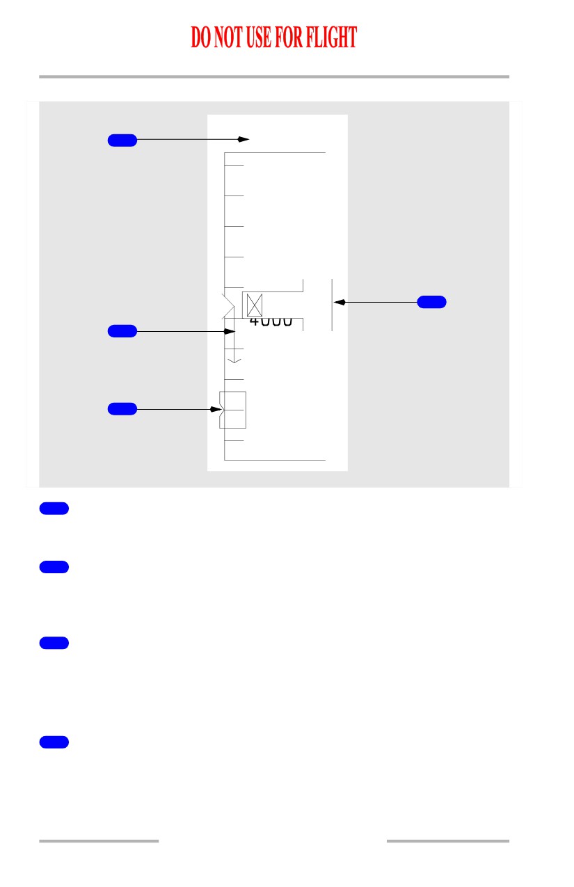
Altitude Indications
1
3700
4400
4200
80
4
4
0
60
40
2
3800
3
3600
1
Selected Altitude (PRI in flight, PRI ground modes)
Indicates the altitude set in the MCP altitude window.
2
Altitude Trend Vector (PRI in flight mode)
Tip of arrow indicates predicted altitude in the next 6 seconds based on the current
vertical speed.
3
Selected Altitude Bug (PRI in flight, PRI ground modes)
Points to the altitude set in the MCP altitude window.
When the selected altitude is off scale, the bug is parked at the top or bottom of
the tape, with only one half bug visible.
4
Current Altitude (PRI in flight, PRI ground modes)
Indicates current altitude in increments of thousands, hundreds and twenty feet.
10.12.8
Flight Instruments, Displays -
Head-Up Display System -
Displays
Boeing 737 Operations Manual
For positive values of altitude below 10,000 feet, an “X” symbol is displayed.
Note: In other than the PRI mode, the altitude scale and associated symbols are
replaced with a digital readout. The readout is positioned relative to the
flight path vector. If the flight path vector is not displayed, the readout is
positioned relative to the airplane reference symbol.
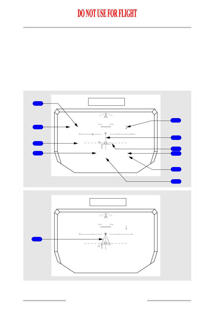
Approach Mode Displays
[Option - Model 2350]
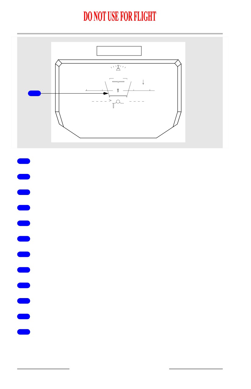
Refer to section 42 for symbology descriptions.
1
IMC Mode
MCP SPD
VOR/LOC
H 310
G/S
FD
5
AS
5
5
2
125
IMC
30
31
10
32
6
3
-3.00
-3.00
7
4
120
450
B
8
900
-600
VS
GS
110
DME
5.0
ILS1
9
10
AIII Mode
H 310
FD
AS
5
5
125
AIII
30
31
10
32
11
-3.00
-3.00
120
450
B
250
-600
VS
GS
118
DME
13.4
ILS1
10.12.9
Flight Instruments, Displays -
Head-Up Display System -
Displays
Boeing 737 Operations Manual
VMC Mode
H 310
AS
5
5
125
VMC
10
30
31
32
12
-3.00
-3.00
120
450
B
900
-600
VS
GS
110
DME
5.0
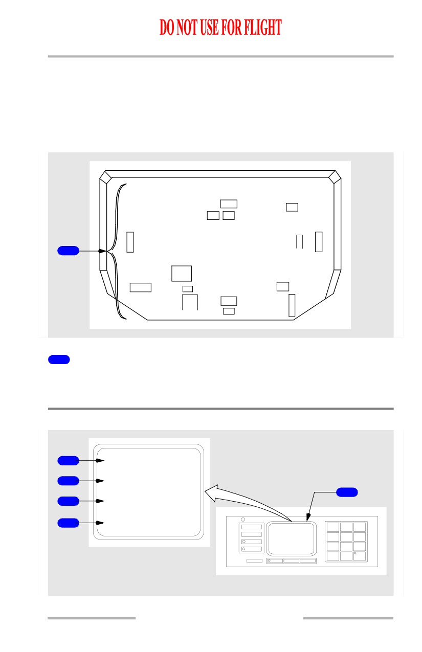
1
Mode/Status
2
Digital Selected Airspeed
3
Glideslope Reference Line
4
Digital Airspeed
5
Wind Indications
6
Lateral Deviation Line
7
Glideslope Deviation Line
8
Digital Barometric Altitude
9
Digital Vertical Speed
10
Radio Altitude
11
Runway Edge Lines
12
TCAS Resolution Advisory
10.12.10
Flight Instruments, Displays -
Head-Up Display System -
Displays
Boeing 737 Operations Manual
Failure Indications and Flags
Dashes replace numbers if there is no computed information. Failure flags replace
symbols or failure messages are displayed, as appropriate.
Data source flags are provided in a few cases to annunciate the source of displayed
data when other than normal.
[Option - Model 2350]
SEL SPD
ROLL ATT PITCH
SEL ALT
NO
FD
VSPD
DH RA
S
G
A
P
/
L
S
D
T
1
SPD
LIM
TCAS
LOC CMP
FAIL
MACH
DME
VS
ATT2
VOR
V
HDG
ILS
T
LOC
K
1
HUD System Failure Indications and Flags
See section 42 for detailed information on the HUD system failure indications and
flags.
Control Panel Display
2
PRI
3
I M C A I I I
1
4
L
1 0 0 0 0 ’
5
— 3 . 0 0 °
MODE
1
2
3
H
STBY
G
4
5
6
S
RWY
G/S
7
8
9
ENTER
0
TEST
FAULT
CLR
BRT +
DIM -
AFT ELECTRONIC PANEL
10.12.11
Flight Instruments, Displays -
Head-Up Display System -
Displays
Boeing 737 Operations Manual
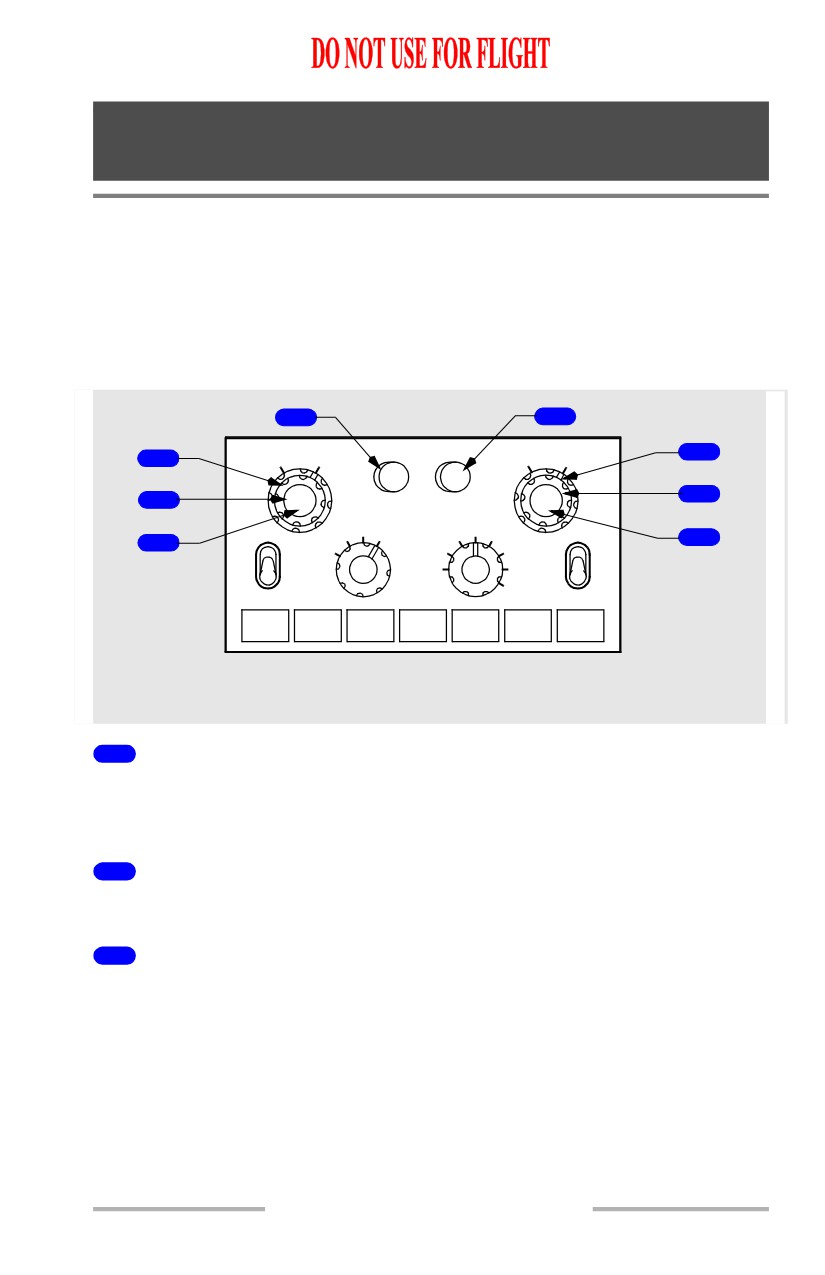
1
Control Panel Display Window
Displays selected modes, entered values, system test and system status.
2
Mode Display Line
Displays current mode:
• PRI - primary flight mode
• AIII - Cat III approach mode
• IMC - instrument meteorological conditions approach mode
• VMC - visual meteorological conditions approach mode
• NO AIII - AIII capability lost
• CLR - combiner display cleared.
3
Standby Mode Display Line
Displays standby mode:
• PRI - primary flight mode
• AIII - Cat III approach mode
• IMC - instrument meteorological conditions approach
• VMC - visual meteorological conditions approach.
[Option - Model 2350]
When available, AIII capability status is displayed adjacent to the standby mode.
“AIII” changes to “AIII” and moves to the standby mode once all conditions have
been met to conduct an AIII mode approach. Pressing the mode key then
activates the AIII mode.
4
Runway Length/Elevation Line
Displays runway length or elevation:
• L XXXXX - valid entry is 0 to 99999 feet, however, entries between 7500
and 13500 feet are required to display ground roll guidance for low
visibility takeoff operations.
• E XXXXX - valid entry is -9999 to 99999 feet.
5
Reference Glideslope Line
Displays runway glideslope:
• valid entry is 0.00° to -9.99°.
• entered values are required to be between -2.51° and -3.00° for AIII
approach operations.
10.12.12
Boeing 737 Operations Manual
Flight Instruments, Displays
Chapter 10
EFIS Instruments - Controls and Indicators
Section 15
EFIS Control Panel (EFIS/Map Display)
The left EFIS control panel controls the Captain outboard and inboard display
units. The right EFIS control panel controls the First Officer outboard and inboard
display units.
EFIS Control Panel Controls - Flight Instrument Displays
[Option - Flight path vector, dual ADF
8
4
FPV
MTRS
BARO
5
1
RADIOMINS BARO
IN
HPA
2
RST
STD
6
MAP
40
VOR 1
VOR
PLN
20
80
VOR 2
7
3
APP
10
160
OFF
OFF
CTR
5
TFC
320
ADF 1
640
ADF 2
WXR
STA
WPT
ARPT
DATA
POS
TERR
GLARESHIELD
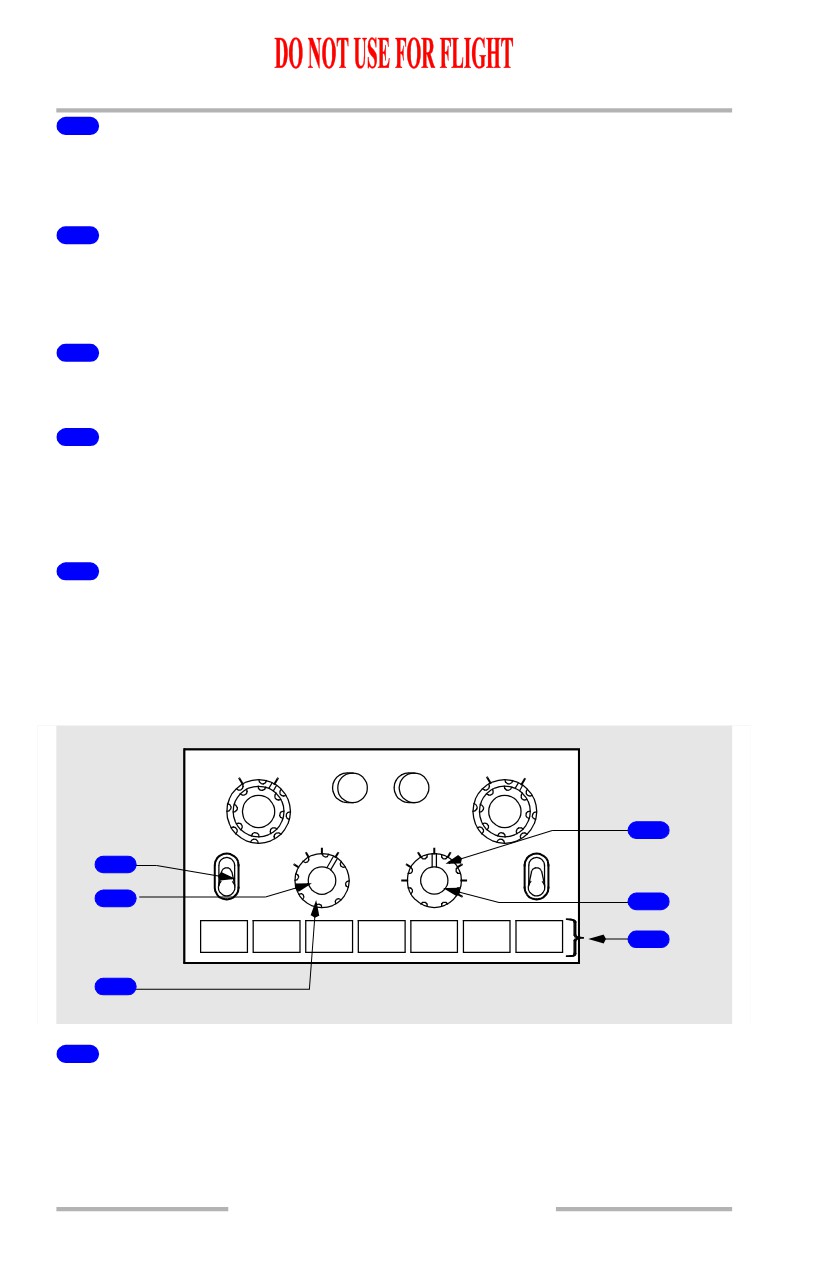
1
Minimums (MINS) Reference Selector (outer) (two position)
RADIO - selects radio altitude as the minimums reference.
BARO - selects barometric altitude as the minimums reference.
2
Minimums (MINS) Selector (middle) (slew)
ROTATE - adjusts the radio or baro minimums altitude.
3
Minimums (MINS) Reset (RST) Switch (inner) (momentary action)
PUSH -
• blanks radio height ALT alert
• resets the radio altitude minimums alert display on the attitude indicator
• blanks the reference altitude marker on the altimeter if displayed; sets the
reference altitude marker to zero if not previously displayed.
10.15.1
Flight Instruments, Displays -
EFIS Instruments - Controls and
Indicators
Boeing 737 Operations Manual
4
Meters (MTRS) Switch (momentary action)
PUSH - displays altitude indications in meters. Not available in compact display
format.
5
Barometric (BARO) Reference Selector (outer) (two position)
IN - selects inches of mercury as the barometric altitude reference.
HPA - selects hectopascals as the barometric altitude reference.
6
Barometric (BARO) Selector (middle) (slew)
ROTATE - adjusts the barometric altitude setting on the altimeter.
7
Barometric (BARO) Standard (STD) Switch (inner) (momentary
action)
PUSH - selects the standard barometric setting (29.92 inches Hg/1013 HPA) for
barometric altitude reference.
8
Flight Path Vector (FPV) Switch (momentary action)
[Option - Flight path vector]
PUSH - displays flight path vector on the attitude indicator.
EFIS Control Panel Controls - Navigation Displays
[Option - Dual ADF, flight path vector]
FPV
MTRS
BARO
RADIOMINS BARO
IN
HPA
RST
STD
4
MAP
40
VOR 1
VOR
PLN
20
80
VOR 2
APP
10
160
1
OFF
OFF
CTR
5
TFC
320
2
640
5
ADF 1
ADF 2
WXR
STA
WPT
ARPT
DATA
POS
TERR
6
3
GLARESHIELD
1
VOR/ADF Switch (three position)
Displays VOR or ADF information on the respective RDMI.
VOR - displays the selected VOR bearing pointer and VOR bearing pointer
source indicator.
10.15.2
Flight Instruments, Displays -
EFIS Instruments - Controls and
Indicators
Boeing 737 Operations Manual
OFF - removes the VOR or ADF displays and displays “OFF” in place of the
bearing pointer source indicators.
ADF - displays the selected ADF pointer and ADF bearing pointer source
indicator.
2
Mode Selector (outer)
Selects the desired display.
APP -
• displays localizer and glideslope information in heading-up format
• displays reference ILS receiver, ILS frequency, course and DME
• weather radar and TCAS are not displayed in center APP mode.
VOR -
• displays VOR navigation information in heading-up format
• displays reference VOR receiver, VOR frequency, course, DME and
TO/FROM information
• weather radar and TCAS are not displayed in center VOR mode.
MAP -
[Option - Heading-up display]
• displays FMC generated route and MAP information, airplane position,
heading and track, in a heading-up format
• displays waypoints, including the active waypoint, within the selected
range
• displays VNAV path deviation.
PLN -
• displays a non-moving, true north up, route depiction
• the airplane symbol represents actual airplane position
• allows route step-through using the CDU LEGS page
• weather radar and TCAS are not displayed.
3
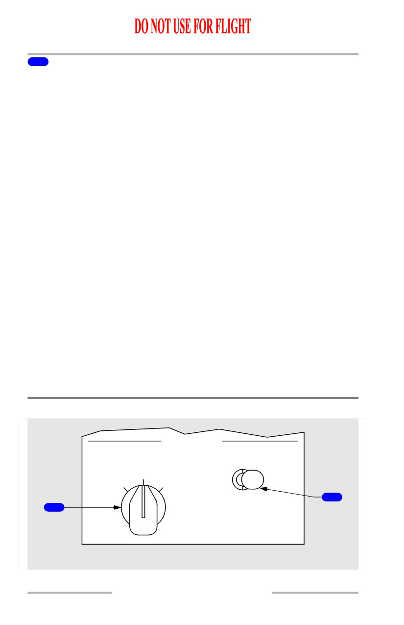
Center (CTR) Switch (inner)
PUSH -
• displays the full compass rose (center) for APP, VOR and MAP modes
• subsequent pushes alternate between expanded and center displays.
4
Range Selector (outer)
Selects desired display range in nautical miles for APP, VOR, MAP or PLN mode.
5
Traffic (TFC) Switch (inner)
PUSH - displays TCAS information (refer to Chapter 15, Warning Systems).
10.15.3
Flight Instruments, Displays -
EFIS Instruments - Controls and
Indicators
Boeing 737 Operations Manual
6
MAP Switches (momentary action)
The MAP switches:
• add background data/symbols to MAP and center MAP modes
• displays can be selected simultaneously
• second push removes the information.
WXR (weather radar) - energizes weather radar transmitter and displays weather
radar returns in MAP, center MAP, expanded VOR and expanded APP modes.
When the 640 nm range is selected, weather radar returns are limited to 320 nm
(refer to Chapter 11, Flight Management, Navigation).
STA (station) -
• displays all FMC data base navigation aids if on map scales 5, 10, 20 or
40 nm.
• displays FMC data base high altitude navigation aids on map scales 80,
160, 320 or 640 nm.
WPT (waypoint) - displays the waypoints in the FMC data base which are not in
the flight plan route if the selected range is 40 nm or less.
ARPT (airport) - displays all airports which are stored in the FMC data base and
which are within the viewable map area.
DATA - displays altitude constraint, if applicable, and estimated time of arrival
for each active route waypoint.
POS (position) - displays VOR and ADF bearing vectors extended from the nose
of the airplane symbol to the stations.
TERR (terrain) - displays GPWS generated terrain data in MAP, center MAP,
VOR, and APP modes (refer to Chapter 15, Warning Systems).
Displays Source Panel
DISPLAYS
SOURCE
CONTROL PANEL
AUTO
BOTH
BOTH
ALL
ALL
ON 1
ON 2
ON 1
ON 2
NORMAL
2
1
FORWARD OVERHEAD PANEL
10.15.4
Flight Instruments, Displays -
EFIS Instruments - Controls and
Indicators
Boeing 737 Operations Manual
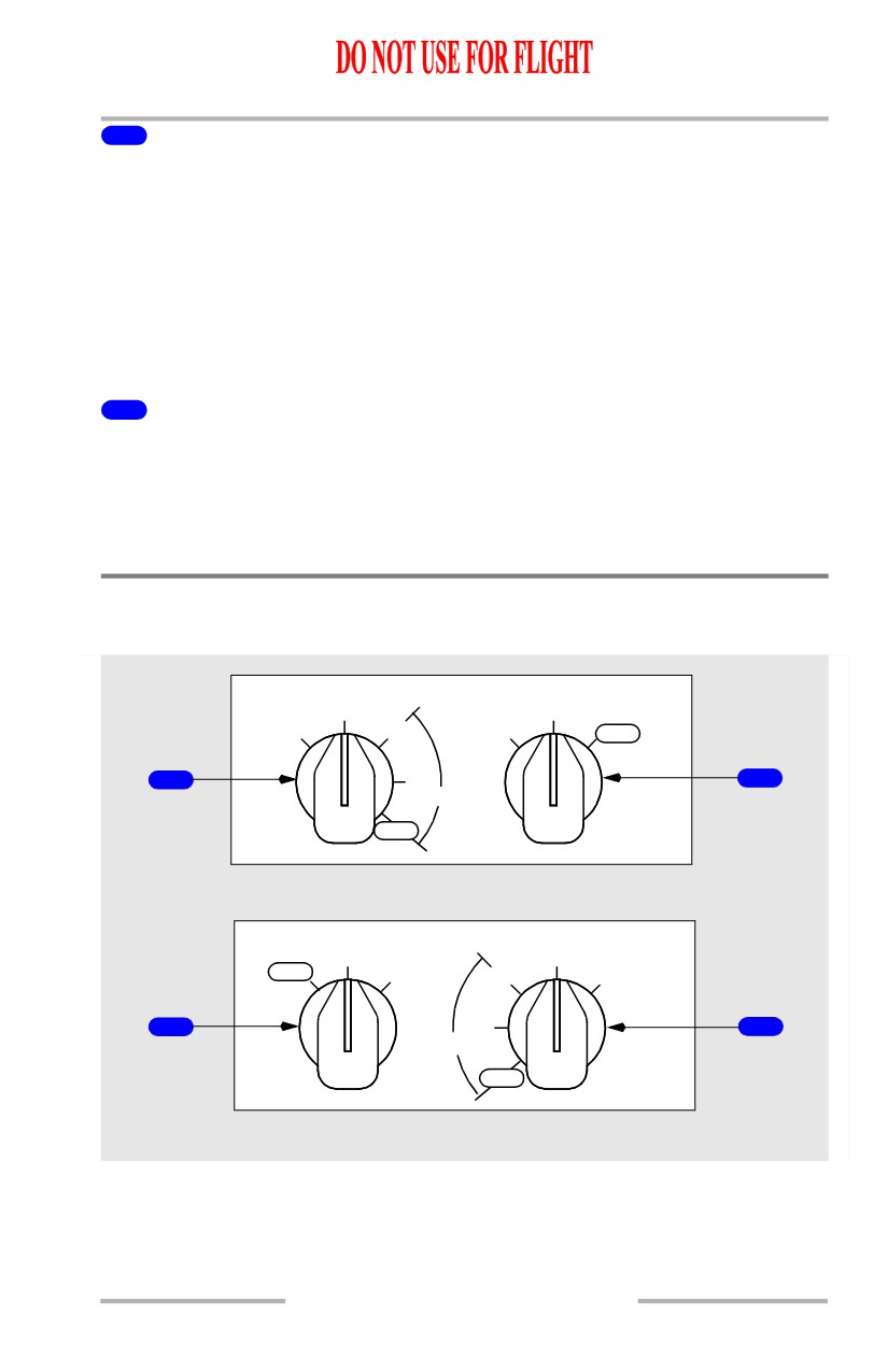
1
DISPLAYS SOURCE Selector
AUTO - DEU 1 controls the Captain outboard, Captain inboard, and the upper
display units; DEU 2 controls the First Officer outboard, First Officer inboard, and
the lower display units. When a DEU fails, the other DEU controls all display
units.
ALL ON 1/ALL ON 2 - provides a means of manually switching to a single DEU
as the source of information for all six display units.
Note: Used on the ground for maintenance purposes.
2
CONTROL PANEL Select Switch
NORMAL - the left EFIS control panel controls the Captain’s displays and the
right EFIS control panel controls the First Officer’s displays.
BOTH ON 1/BOTH ON 2 - provides a means of manually switching control of
the Captain’s and First Officer’s displays to a single EFIS control panel.
Display Select Panels
[Option - Side by side display]
MAIN PANEL DUs
LOWER DU
NORM
NORM
OUTBD
ENG
ENG
INOP
PFD
PRI
PRI
1
2
PFD
INBD
INOP
LEFT FORWARD PANEL
LOWER DU
MAIN PANEL DUs
NORM
NORM
INOP
ENG
ENG
OUTBD
PRI
PRI
PFD
2
PFD
1
INBD
INOP
RIGHT FORWARD PANEL
10.15.5
Flight Instruments, Displays -
EFIS Instruments - Controls and
Indicators
Boeing 737 Operations Manual
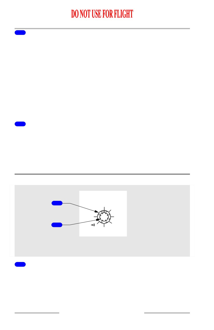
1
Main Panel Display Units (MAIN PANEL DUs) Selector
Selects what is displayed on the respective outboard and inboard display units:
• Outboard Primary Flight Display (OUTBD PFD) - displays the compact
EFIS format on the outboard display unit and blanks the inboard display
unit.
• Normal (NORM) - displays normal EFIS and MAP displays on the
outboard and inboard display units; provides automatic display switching
if a display unit fails.
• Inboard Engine Primary (INBD ENG PRI) - displays the engine display
on the inboard display unit and the compact EFIS format on the outboard
display unit.
• Inboard Primary Flight Display (INBD PFD) - displays the compact EFIS
format on the inboard display unit and blanks the outboard display unit.
2
Lower Display Unit (LOWER DU) Selector
Selects what is displayed on the lower display unit:
• Engine Primary (ENG PRI) - displays the engine display on the lower
display unit and blanks the upper display unit.
• Normal (NORM) - displays the engine display on the upper display unit
and no display on the lower display unit; provides automatic display
switching to the lower display unit if the upper display unit fails.
Speed Reference Selector
SPD REF
1
AUTO
V1
SET
VR
2
WT
REF
V
CENTER FORWARD
PANEL
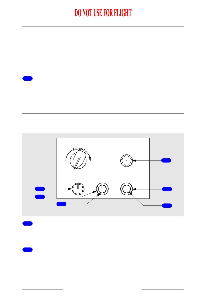
1
Speed Reference Selector (outer)
Sets the reference airspeed bugs on the Mach/airspeed indicator:
• AUTO - the reference airspeeds and gross weight are provided
automatically through the FMC
• V1 - used to manually set decision speed on the ground; in flight, displays
“INVALID ENTRY”
10.15.6
Flight Instruments, Displays -
EFIS Instruments - Controls and
Indicators
Boeing 737 Operations Manual
• VR - used to manually set rotation speed on the ground; in flight, displays
“INVALID ENTRY”
• WT - allows manual entry of reference gross weight
• VREF - used to manually set the landing reference speed in flight; on the
ground, displays “INVALID ENTRY”
• Bug 5 - used to manually set the white bug 5 to the desired value
• SET - removes the digital readout above the Mach/airspeed indicator.
2
Speed Reference Selector (inner) (two speed slew)
ROTATE -
• manually sets the appropriate reference airspeed or gross weight
• the digital display appears above the Mach/airspeed indicator.
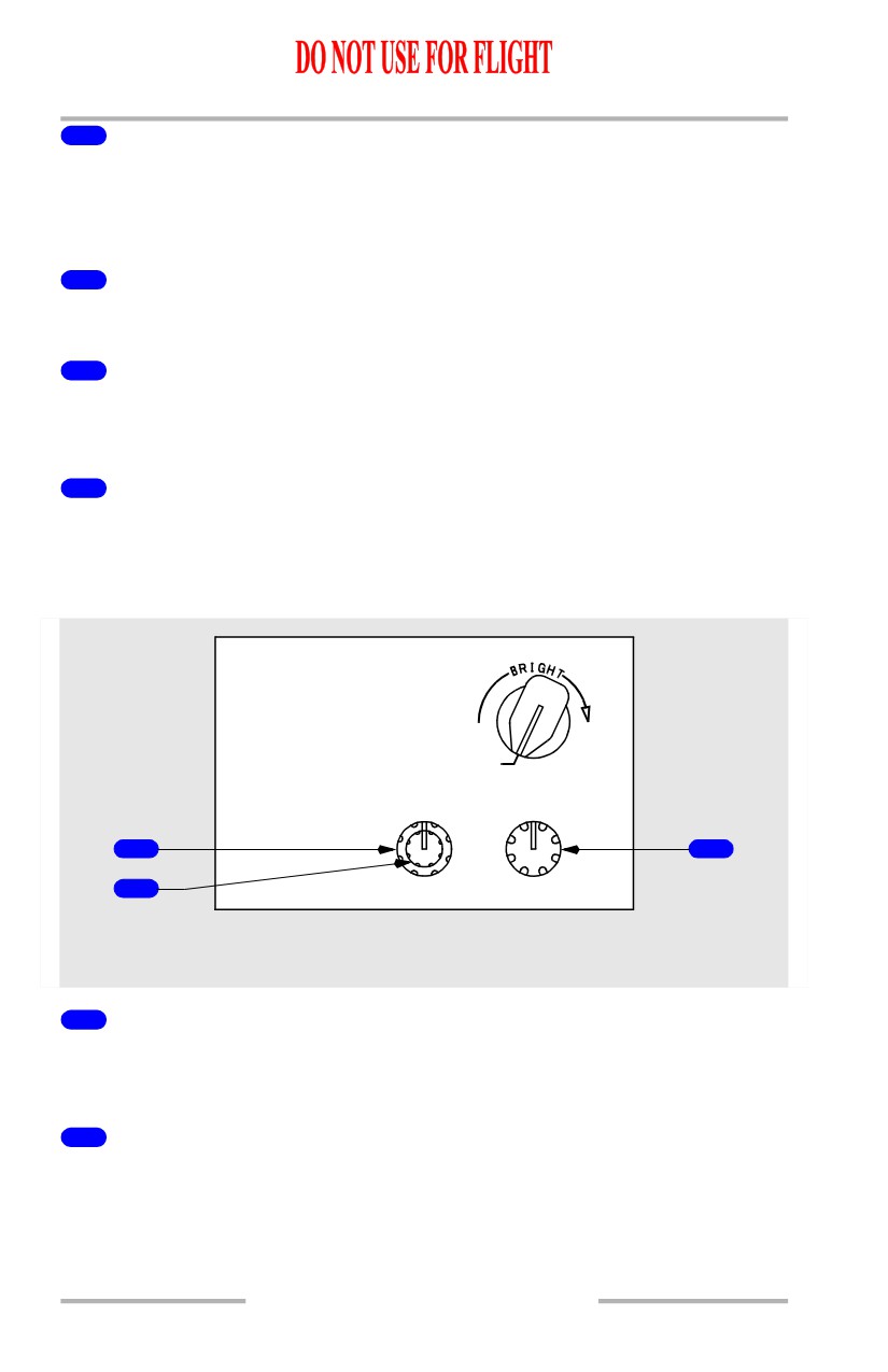
Display Brightness Controls
Captain Brightness Controls
MAIN PANEL
UPPER DU
BRT
4
OFF
OUTBD DU
INBD DU
LOWER DU
BRT
BRT
BRT
1
5
2
3
6
LEFT FORWARD PANEL
1
Outboard Display Unit Brightness (OUTBD DU BRT) Control
(rotary)
ROTATE - adjusts the brightness of the Captain outboard display unit.
2
Inboard Display Unit Brightness (INBD DU BRT) Control (outer)
(rotary)
ROTATE - adjusts the brightness of the Captain inboard display unit.
10.15.7
Flight Instruments, Displays -
EFIS Instruments - Controls and
Indicators
Boeing 737 Operations Manual
3
Inboard Display Unit Radar Brightness (INBD DU BRT) Control
(inner) (rotary)
ROTATE - adjusts weather radar and terrain display brightness on the Captain
inboard display unit.
4
Upper Display Unit Brightness (UPPER DU BRT) Control (rotary)
ROTATE - adjusts the brightness of the upper display unit.
5
Lower Display Unit Brightness (LOWER DU BRT) Control (outer)
(rotary)
ROTATE - adjusts the brightness of the lower display unit.
6
Lower Display Unit Brightness (LOWER DU BRT) Control (inner)
(rotary)
Inoperative.
First Officer Brightness Controls
MAIN PANEL
OFF
INBD DU
OUTBD DU
BRT
BRT
1
3
2
RIGHT FORWARD PANEL
1
Inboard Display Unit Brightness (INBD DU BRT) Control (outer)
(rotary)
ROTATE - adjusts the brightness of the First Officer inboard display unit.
2
Inboard Display Unit Radar Brightness (INBD DU BRT) Control
(inner) (rotary)
ROTATE - adjusts weather radar and terrain display brightness on the First
Officer inboard display unit.
10.15.8
Flight Instruments, Displays -
EFIS Instruments - Controls and
Indicators
Boeing 737 Operations Manual
3
Outboard Display Unit Brightness (OUTBD DU BRT) Control
(rotary)
ROTATE - adjusts the brightness of the First Officer outboard display unit.
10.15.9
Flight Instruments, Displays -
EFIS Instruments - Controls and
Indicators
Boeing 737 Operations Manual
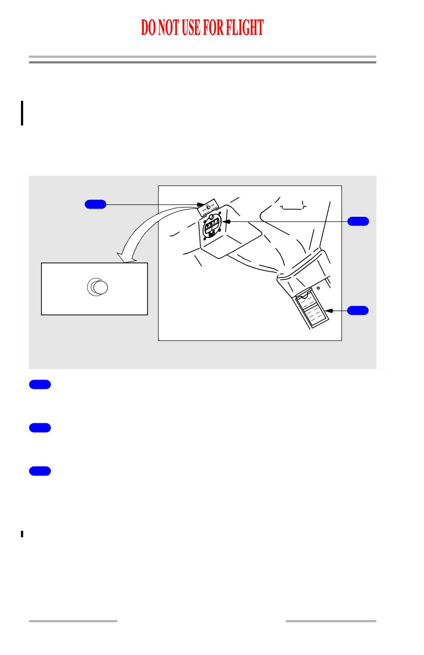
Standby Flight Instruments
The standby flight instruments include the:
• standby magnetic compass
• integrated standby flight
display
• standby radio magnetic
indicator.
Standby Magnetic Compass
3
1
OFF
DIM
BRT
COMPASS LIGHT
2
CENTER POST ABOVE GLARESHIELD
1
Standby Magnetic Compass
Displays magnetic heading.
2
Standby Magnetic Compass Correction Card
Provides appropriate heading corrections.
3
Compass Light Switch
OFF - compass light is extinguished.
BRT - sets compass light to full brightness.
DIM - sets compass light to low brightness.
10.15.10
Flight Instruments, Displays -
EFIS Instruments - Controls and
Indicators
Boeing 737 Operations Manual
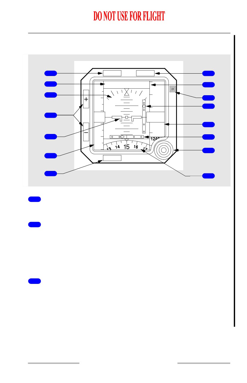
Integrated Standby Flight Display
[Option - Sextant S231A120-1]
1
APP
HP/IN
8
2
APP
29.92 IN
9
13200
240
3
10
13000
220
10
11
4
1
40
20
12
7
0
20
12600
12
10
180
5
13
160
14
6
ATT
RST
BARO
7
15
CENTER INSTRUMENT PANEL
1
Approach (APP) Switch
Push - selects approach mode.
2
Approach Mode Annunciation
Indicates approach mode selected.
• Blank - no approach deviation data displayed
• APP - ILS localizer and glideslope deviation data displayed
• BCRS (Back course) - reverses sensing for localizer pointer during back
course approaches
3
Attitude Display
Displays airplane attitude.
• Indicates bank in reference to the bank scale
• Indicates the horizon relative to the airplane symbol
• Beyond 30 degrees pitch, large red arrowheads (V-shaped) indicate the
attitude has become excessive, and the direction to the horizon line.
10.15.11