Boeing 737 - 600/700/800/900. Operations Manual (1997 year) - page 45
Flight Instruments, Displays -
PFD/ND - Displays
Boeing 737 Operations Manual
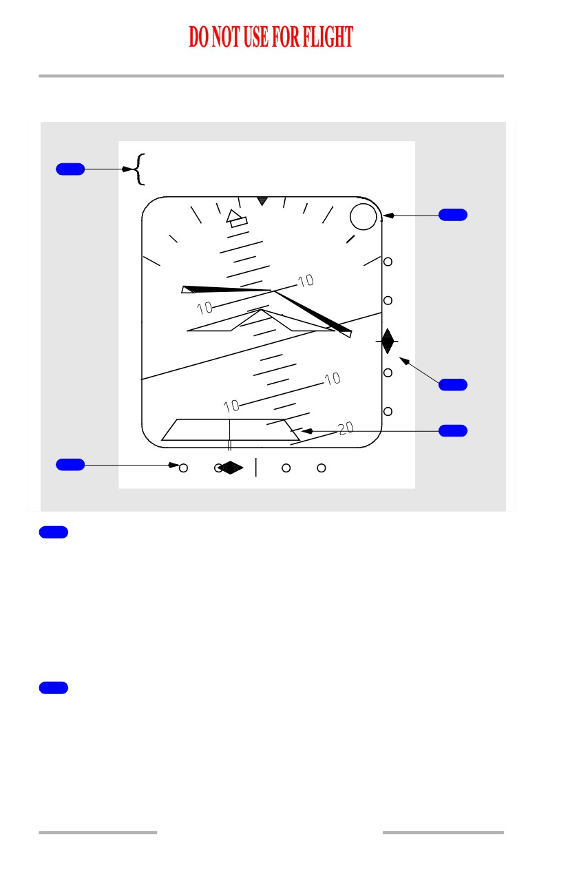
PFD Instrument Landing System Indications
[Option - Integrated cue command bar, rising runway]
IBFI/130°
1
DME 3.4
3
MM
4
5
2
1
Approach Reference
Displays the selected ILS identifier or frequency, approach front course, and
ILS/DME distance.
If the tuned ILS frequencies disagree, the frequency turns amber with an amber
horizontal line through it.
If the approach courses entered in the MCP disagree, the course turns amber with
an amber horizontal line through it.
2
Localizer Pointer and Deviation Scale
The pointer:
• indicates localizer position relative to the airplane
• in view when the localizer signal is received
• fills in solid magenta when within 21/2 dots from center.
10.11.16
Flight Instruments, Displays -
PFD/ND - Displays
Boeing 737 Operations Manual
The scale:
• indicates deviation
• in view when the localizer frequency is tuned
• expands when the localizer is engaged and deviation is slightly more than
one-half dot.
At low radio altitudes, with autopilot engaged, the scale turns amber and the
pointer flashes to indicate excessive localizer deviation.
Below 1,000 feet AGL, with LNAV engaged and LOC armed, the localizer scale
turns amber and the pointer flashes if the localizer is not captured.
Each pilot’s deviation alerting system self-tests upon becoming armed at 1500 feet
radio altitude. This self-test generates a two second LOC deviation alerting
display on each attitude indicator.
3
Marker Beacon symbol
Flashes when over one of the marker beacons:
OM (cyan) - an outer marker beacon
MM (amber) - a middle marker beacon
IM (white) - an airway or inner marker.
4
Glide Slope Pointer and Deviation Scale
The pointer:
• indicates glide slope position
• in view when the glide slope signal is received
• fills in solid magenta when within 21/2 dots from center.
• not displayed when the track and the front course on the mode control
panel differ by more than 90 degrees (backcourse).
The scale:
• indicates deviation
• in view when the localizer frequency is tuned.
At low radio altitudes, with autopilot engaged, the scale turns amber and the
pointer flashes to indicate excessive glide slope deviation.
Each pilot’s deviation alerting system self-tests upon becoming armed at 1500 feet
radio altitude. This self-test generates a two second G/S deviation alerting display
on each attitude indicator.
10.11.17
Flight Instruments, Displays -
PFD/ND - Displays
Boeing 737 Operations Manual
5
Rising Runway (green with magenta stem)
[Option - Rising runway]
Displayed when:
• localizer signal usable and pointer is in view
• radio altitude is less than 2500 feet.
Rises towards airplane symbol when radio altitude is below 200 feet.
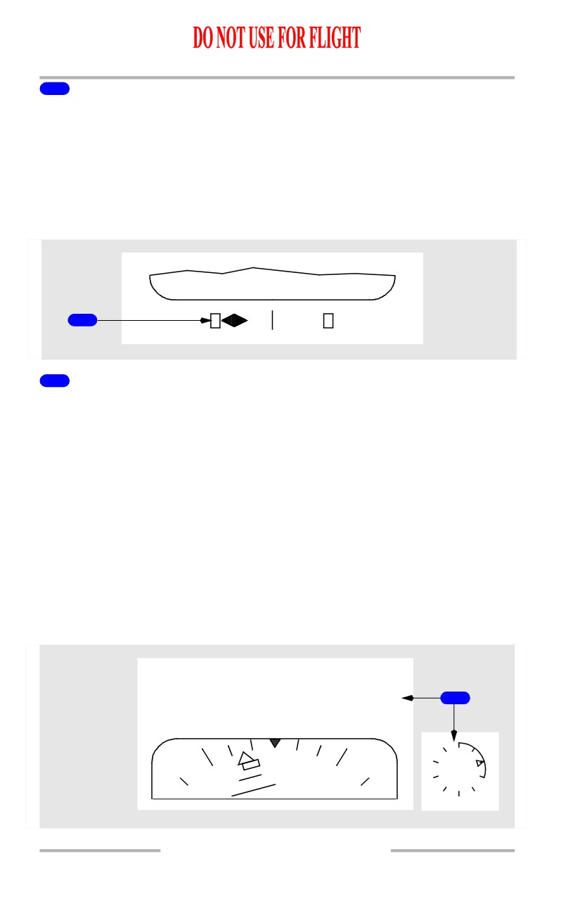
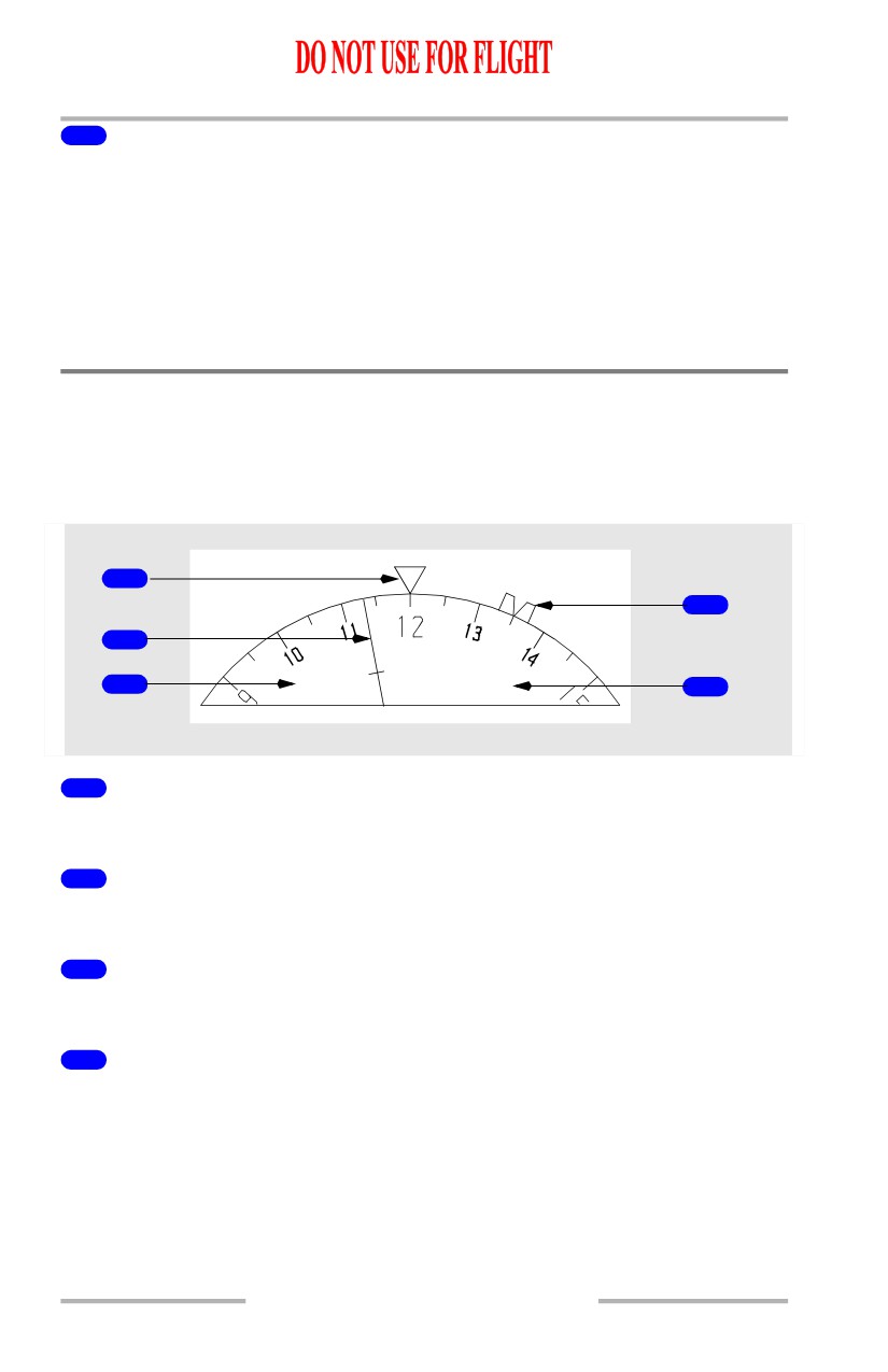
Expanded Localizer Indications
1
1
Expanded Localizer Scale
[Option - Autopilot or flight director activation]
Displayed when the autopilot or flight director is in LOC mode, deviation is
slightly more than one half dot and track is within 5 degrees of the MCP selected
course.
As deviation increases, the deviation pointer remains filled in solid magenta and
parks at the limit of the expanded scale. Once the deviation reaches the equivalent
of 2.4 dots from center on the standard scale, the pointer becomes unfilled.
Reverts to standard scale when out of LOC mode, and groundspeed is less than 30
knots or radio altitude is greater than 200 feet.
A rectangle equals 1/2 dot deviation.
PFD Radio Altitude Indications
[Option - Radio altitude above, round dial]
1250
1
300
10.11.18
Flight Instruments, Displays -
PFD/ND - Displays
Boeing 737 Operations Manual
1
Radio Altitude - Round Dial
[Option - Radio altitude above, round dial]
Displayed below 2500 feet AGL:
• digital display from 2500 to 1000 feet AGL
• box highlighted white for 10 seconds upon descent below 2500 feet
• round dial displays below 1000 feet AGL
• pointer indicates selected radio altitude minimums
• the circumference of the dial is added to, or taken away from, to depict the
airplane’s radio altitude
• the remaining perimeter and pointer turn amber and flash for 3 seconds
when below radio altitude minimums, the numeric readout does not flash.
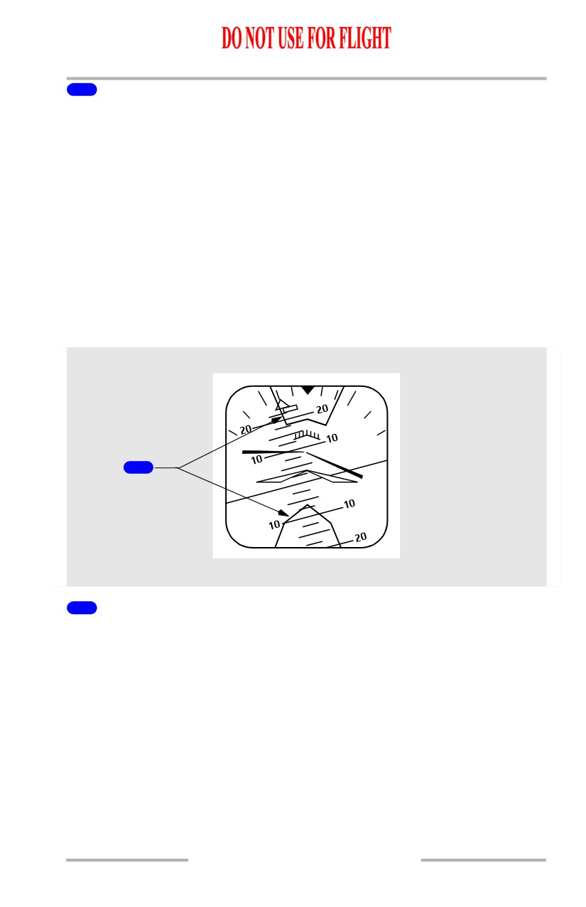
Traffic Alert and Collision Avoidance Indications
[Option - Integrated cue command bar]
1
1
Traffic Alert and Collision Avoidance System Pitch Command (red)
The area(s) inside the red lines indicate(s) the pitch region(s) to avoid in order to
resolve the traffic conflict. The airplane symbol must be outside the TCAS pitch
command area(s) to ensure traffic avoidance. Refer to Chapter 15, Warning
Systems.
10.11.19
Flight Instruments, Displays -
PFD/ND - Displays
Boeing 737 Operations Manual
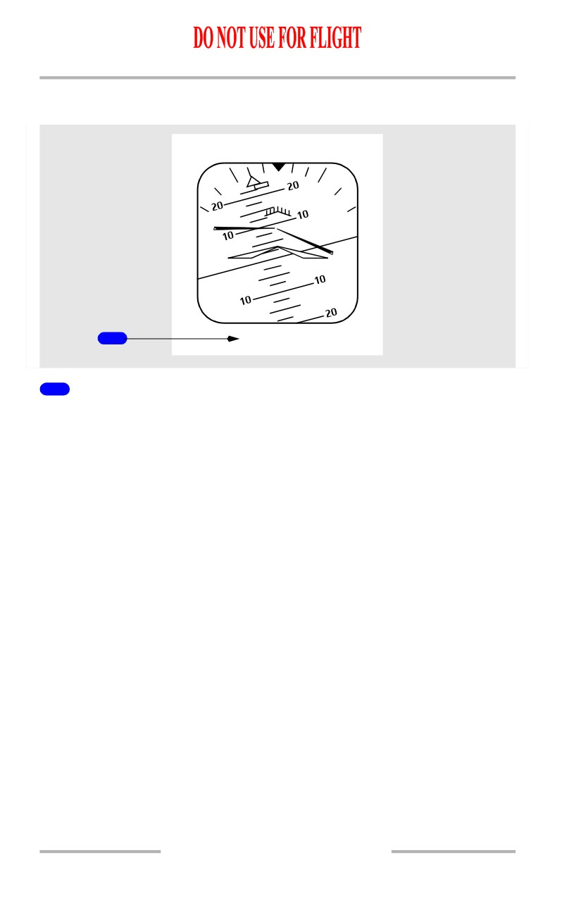
GPWS Annunciations
[Option - Integrated cue command bar]
1
PULL UP
1
GPWS Annunciations (red)
Displays WINDSHEAR or Pull UP alert.
Refer to Chapter 15, Warning Systems.
10.11.20
Flight Instruments, Displays -
PFD/ND - Displays
Boeing 737 Operations Manual
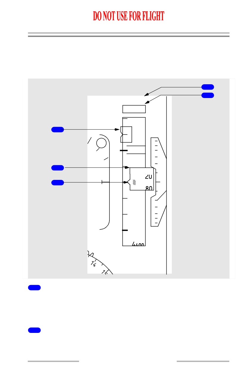
PFD - Altitude Indications
Altitude Indications- General
The altitude
indication
displays
ADIRS altitude
and
other
altitude
related
information.
4
5
M
1554
5100
5200
1
6
OM
5
000
2
1
2
1463M
3
4
800
1
4
600
2
6
1000
BARO
450
1011 HPA
1
Selected Altitude Bug (magenta)
Indicates the altitude set in the MCP altitude window.
When the selected altitude is off scale, the bug is parked at the top or bottom of
the tape, with only one half the bug visible.
2
Metric Digital Readout (readout and box-white, metric symbol-cyan)
Displays current altitude in meters when MTRS is selected on the EFIS control
panel.
10.11.21
Flight Instruments, Displays -
PFD/ND - Displays
Boeing 737 Operations Manual
3
Current Altitude
Displays current altitude in increments of thousands, hundreds and twenty feet:
• for positive values of altitude below 10,000 feet, a green crosshatch
symbol is displayed
• a negative sign appears when altitude below zero feet is displayed
• readout box becomes bold to denote altitude acquisition
• readout box is highlighted in amber and flashes to denote altitude
deviation (refer to Chapter 4, Automatic Flight and Chapter 15, Warning
Systems).
4
Metric Selected Altitude Readout (readout-magenta, metric
symbol-cyan)
Displays MCP altitude in meters when MTRS is selected on the EFIS control
panel.
5
Selected Altitude (magenta)
Displays the altitude set in the MCP altitude window.
The selected altitude box appears in white during an altitude alert. For more
information, refer to Chapter 15, Warning Systems.
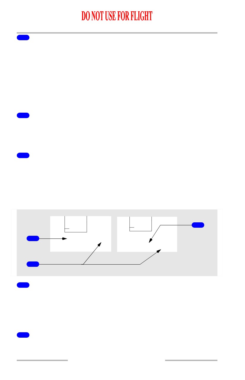
PFD Barometric Indications
[Option - Altimeter with QFE]
2
4 400
24400
1
29.86
IN
QFE
STD
29.86 IN QFE
3
1
Barometric Settings (green)
Indicates the barometric setting in either inches of mercury (IN) or hectopascals
(HPA) as selected on the EFIS control panel.
Display is boxed amber if numeric is set and airplane is climbing above transition
altitude, or if STD is set and descending below transition flight level.
2
Preselected Barometric Setting (white)
STD is displayed when the Barometric Standard (STD) switch is selected on the
EFIS control panel.
10.11.22
Flight Instruments, Displays -
PFD/ND - Displays
Boeing 737 Operations Manual
When STD is displayed, a barometric setting can be preselected on the EFIS
control panel barometric selector and is displayed below STD.
3
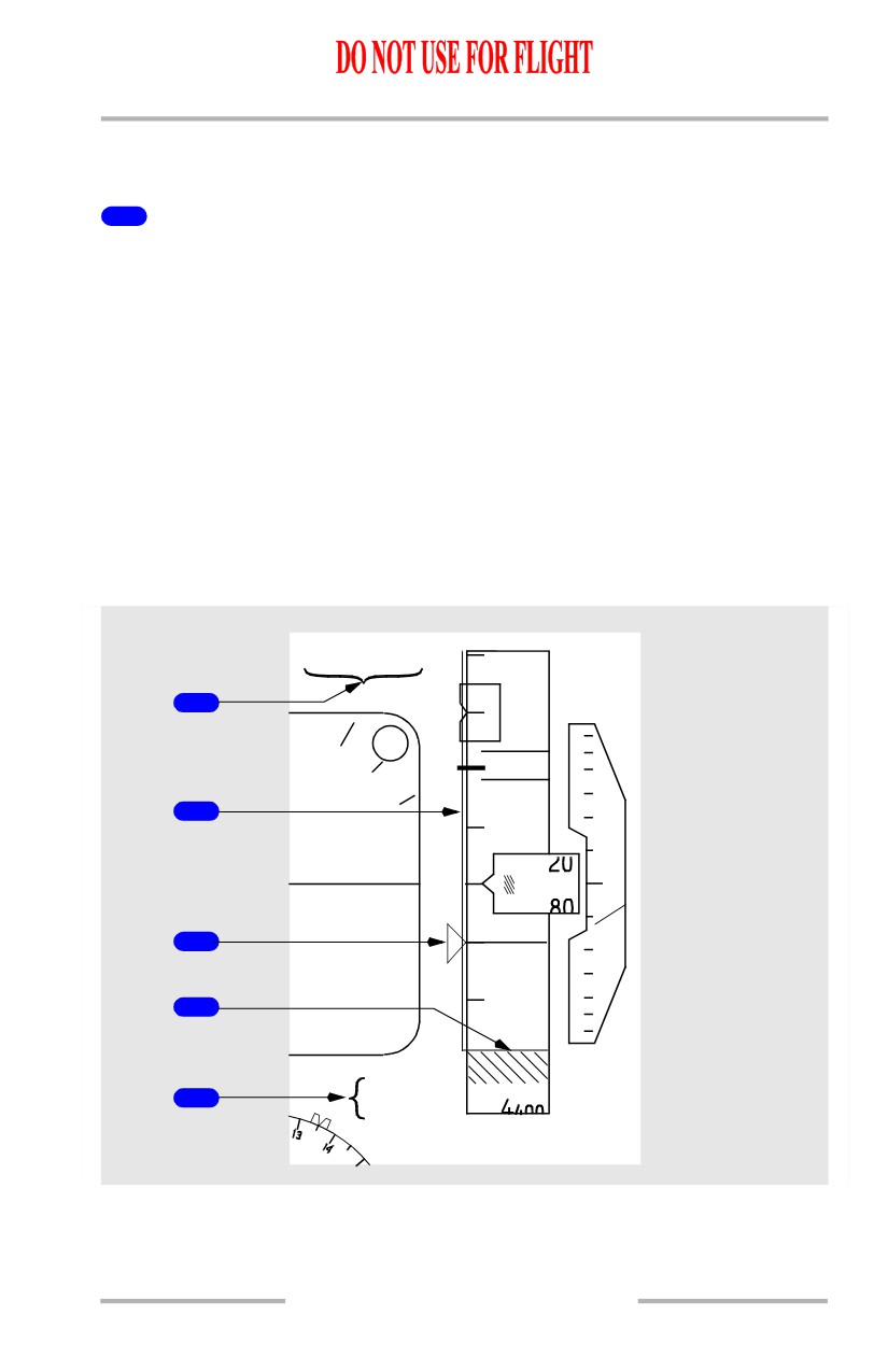
QFE Altitude Reference (green)
[Option - Altimeter with QFE]
Indicates QFE altitude reference if selected on the CDU APPROACH REF Page
or TAKEOFF REF Page 2/2.
When selected, QFE is boxed for 10 seconds.
The altitude tape is shaded green during QFE operation.
When QNH is selected, the green shading is removed; QNH is displayed for 10
seconds, then blanks.
When STD is displayed, QFE in small white characters is displayed below STD,
and a QFE altimeter setting can be preselected.
Landing Altitude/Minimums Indications
[Option - Radio altitude above ADI, landing altitude reference bar]
RADIO
200
5200
3
6
OM
5
000
2
4
1
4
800
1
1
4
600
2
2
6
600
BARO
3
4700
1011 HPA
10.11.23
Flight Instruments, Displays -
PFD/ND - Displays
Boeing 737 Operations Manual
1
BARO Minimums Pointer (green)
Indicates the barometric minimums selected on the EFIS control panel:
• pointer and line turn amber when airplane descends below selected
minimum altitude
• reset with the RST switch on the EFIS control panel.
2
Landing Altitude Indication (amber)
The crosshatched area indicates:
• the FMC landing altitude for the destination runway or airport, or
• the landing altitude for departure runway or airport until 400 NM from
departure or one-half the distance to destination, whichever occurs first.
3
Minimums Reference/Altitude (green)
[Option - Radio altitude above ADI]
Displays approach minimum reference and altitude set by the MINS selector on
the EFIS control panel:
BARO -
• displayed below ADI when selector is set to BARO, minimums are in feet
MSL
• turns amber and flashes for 3 seconds when airplane descends below
selected minimum altitude.
• changes back to green:
• when passing the selected minimum altitude plus
75 feet during
go-around
• at touchdown
• after pressing the RST switch on the EFIS control panel.
RADIO -
• displayed above ADI when selector is set to RADIO, minimums are in
feet AGL
• blank when an altitude less than 0 feet is selected
• turns amber and flashes for 3 seconds when airplane descends below
selected minimum altitude
• changes back to green:
• when passing the selected minimum altitude plus
75 feet during
go-around
• at touchdown
• after pressing the RST switch on the EFIS control panel.
10.11.24
Flight Instruments, Displays -
PFD/ND - Displays
Boeing 737 Operations Manual
4
Landing Altitude Reference Bar
[Option]
Indicates height above touchdown:
• White bar - 500 to 1000 feet above landing altitude
• Amber bar - 0 to 500 feet above landing altitude.
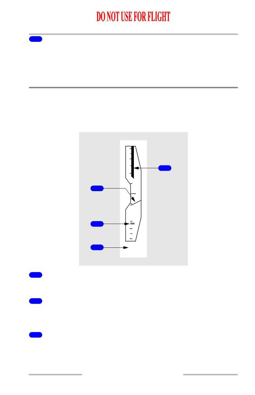
PFD - Vertical Speed Indications
Vertical Speed Indications - General
The vertical speed indication displays ADIRS instantaneous vertical speed.
[Option - VSI TCAS advisory]
6
2
4
1
1
1
2
2
6
3
500
1
Vertical Speed Pointer (white)
Indicates current vertical speed.
2
Selected Vertical speed Bug (magenta)
Indicates the speed selected in the MCP vertical speed window with V/S pitch
mode engaged.
3
Vertical speed (white)
Displays vertical speed when greater than 400 feet per minute.
The display is located above the vertical speed indication when climbing and
below when descending.
10.11.25
Flight Instruments, Displays -
PFD/ND - Displays
Boeing 737 Operations Manual
4
TCAS Vertical Speed Tape (red)
[Option - VSI TCAS advisory]
Tape turns red to indicate vertical speed values to avoid or exit during a TCAS
resolution advisory.
Vertical speed pointer is red if it is within the vertical speed tape range.
Supplements TCAS resolution advisory pitch commands on the attitude
indication.
PFD - Heading and Track Indications
Heading and Track Indications- General
The heading and track indications display current FMC/ADIRS heading, track and
other information.
1
4
2
3
135
H
MAG
5
1
Current Heading Pointer (white)
Indicates current heading.
2
Track Pointer (white)
Indicates current track.
3
Selected Heading (magenta)
Digital display of the selected heading bug.
4
Selected Heading Bug (magenta)
Indicates the heading selected on the mode control panel. If the selected heading
exceeds the display range, the bug parks on the side of the compass rose in the
direction of the shorter turn to the heading.
10.11.26
Flight Instruments, Displays -
PFD/ND - Displays
Boeing 737 Operations Manual
5
Magnetic/True Heading Annunciation (green)
Displays selected heading reference:
• MAG indicates display is oriented relative to magnetic north
• TRU indicates display is oriented relative to true north; a white box is
displayed continuously around TRU
• transition from TRU to MAG results in a green box around MAG for 10
seconds
• when TRU is displayed and the airplane descends more than 2000 feet at
a descent rate greater than -800 feet per minute, an amber box is drawn
around TRU; the box flashes for 10 seconds, then turns steady amber.
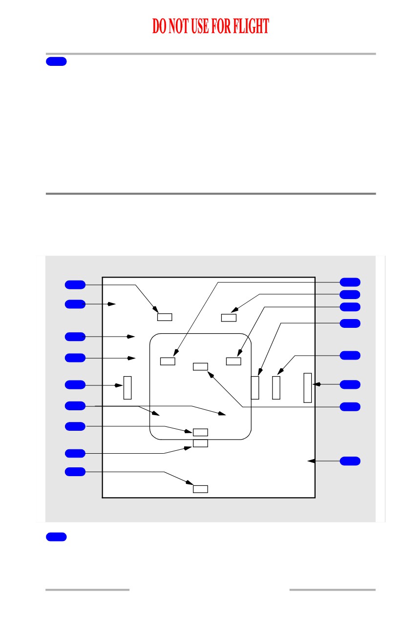
PFD Failure Flags
The flag replaces the appropriate display to indicate source system failure or lack
of computed information.
[Option - Radio altitude below ADI, Angle of Attack indicator
1
10
17
2
SEL SPD
11
DME
AOA
12
SPD
3
LIM
NO
4
V
13
FPV
FD
S
ATT
P
D
V
S
G
A
5
E
14
P
/
L
R
D
S
T
T
6
15
PITCH
ROLL
7
RA
LOC
8
LDG
ALT
16
9
HDG
1
Distance Measuring Equipment (amber)
The DME system has failed.
10.11.27
Flight Instruments, Displays -
PFD/ND - Displays
Boeing 737 Operations Manual
2
Selected Speed (amber)
The selected airspeed data is invalid.
3
Speed Limit Flag (amber)
Displays related with stick shaker or maximum operating speed has failed:
• if the stick shaker warning has failed, the red and black stick shaker speed
bar is removed
• if the maximum operating speed has failed, the red and black maximum
operating speed bar is removed.
4
No V Speeds Flag (amber)
V1 (decision speed) or VR (rotation speed) has not been entered or is invalid.
5
Speed Flag (amber)
The speed indication is inoperative. All indication markings are removed.
6
Pitch/Roll Comparator Annunciation (amber)
PITCH displayed when Captain’s and F/O’s pitch angle displays differ by more
than 5 degrees.
ROLL displayed when Captain’s and F/O’s roll angle displays differ by more than
5 degrees.
[Option - Attitude comparator flashing]
The flags flash for 10 seconds then remain steady.
7
Radio Altitude Flag (amber)
The radio altitude display has failed.
8
Localizer Flag (amber)
An ILS frequency is tuned and the ILS localizer deviation display on the attitude
indication has failed.
9
Heading Flag (amber)
Heading information failed.
10
Flight Path Vector Flag (amber)
FPV is selected on the EFIS control panel, but has failed. De-selection of FPV
removes the flag.
10.11.28
Flight Instruments, Displays -
PFD/ND - Displays
Boeing 737 Operations Manual
11
Flight Director Flag (amber)
The flight director has failed.
12
Glide Slope Flag (amber)
An ILS frequency is tuned and the ILS glide slope deviation display on the attitude
indication has failed.
13
Altitude Flag (amber)
The altitude display has failed.
14
Vertical Speed Flag (amber)
Vertical speed has failed.
15
Attitude Flag (amber)
The attitude display has failed.
16
Landing Altitude Flag (amber)
The landing altitude input is not available or invalid.
17
Angle of Attack (amber)
[Option - Angle of Attack indicator]
The AOA signal has failed or is invalid when ground speed is greater than 80
knots.
10.11.29
Flight Instruments, Displays -
PFD/ND - Displays
Boeing 737 Operations Manual
[Option - Radio altitude above ADI]
9
1
10
2
SEL SPD
DME
RA
11
SPD
3
LIM
12
NO
4
V
13
FPV
FD
S
ATT
P
D
V
S
G
A
5
E
14
P
/
L
R
D
S
T
T
6
15
PITCH
ROLL
LOC
7
LDG
ALT
16
8
HDG
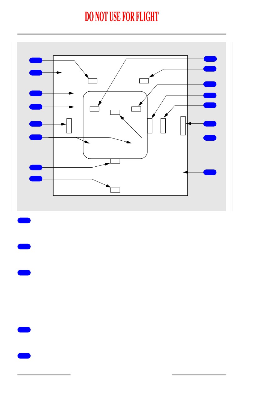
1
Distance Measuring Equipment (amber)
The DME system has failed.
2
Selected Speed (amber)
Invalid data.
3
Speed Limit Flag (amber)
Displays related with stick shaker or maximum operating speed has failed:
• if the stick shaker warning has failed, the red and black stick shaker speed
bar is removed
• if the maximum operating speed has failed, the red and black maximum
operating speed bar is removed.
4
No V Speeds Flag (amber)
V1 (decision speed) or VR (rotation speed) has not been entered or is invalid.
5
Speed Flag (amber)
The speed indication is inoperative. All indication markings are removed.
10.11.30
Flight Instruments, Displays -
PFD/ND - Displays
Boeing 737 Operations Manual
6
Pitch/Roll Comparator Annunciation (amber)
PITCH displayed when Captain’s and F/O’s pitch angle displays differ by more
than 5 degrees.
ROLL displayed when Captain’s and F/O’s roll angle displays differ by more than
5 degrees.
[Option - Attitude comparator flashing]
The flags flash for 10 seconds then remain steady.
7
Localizer Flag (amber)
An ILS frequency is tuned and the ILS localizer deviation display on the attitude
indication has failed.
8
Heading Flag (amber)
Heading information failed.
9
Flight Path Vector Flag (amber)
FPV is selected on the EFIS control panel, but has failed. De-selection of FPV
removes the flag.
10
Radio Altitude Flag (amber)
The radio altitude display has failed.
11
Flight Director Flag (amber)
The flight director has failed.
12
Glide Slope Flag (amber)
An ILS frequency is tuned and the ILS glide slope deviation display on the attitude
indication has failed.
13
Altitude Flag (amber)
The attitude display has failed.
14
Vertical Speed Flag (amber)
Vertical speed has failed.
15
Attitude Flag (amber)
The attitude display has failed.
10.11.31
Flight Instruments, Displays -
PFD/ND - Displays
Boeing 737 Operations Manual
16
Landing Altitude Flag (amber)
The landing altitude input is not available or invalid.
Additional Annunciations and Alerts
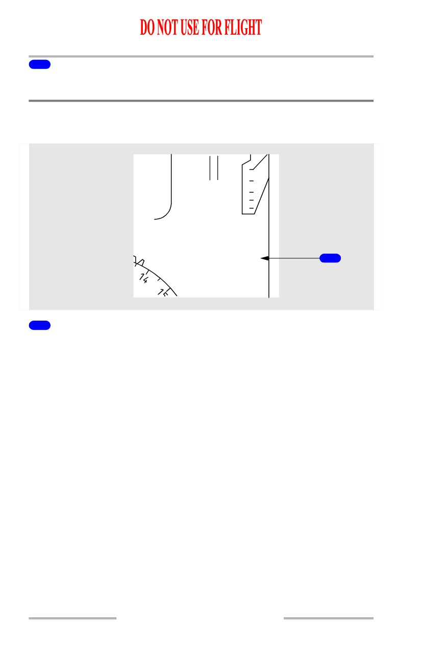
Displays Control Panel Annunciation
A
L
1
T
2
6
1000
BARO
450
DISPLAYS
1
CONTROL PANEL
1
Displays Control Panel Annunciation (amber)
With the CONTROL PANEL select switch on the overhead panel in:
• BOTH ON 1 - left (Capt) EFIS control panel has failed
• NORMAL - corresponding EFIS control panel has failed
• BOTH ON 2 - right (F/O) EFIS control panel has failed.
Altitude information is removed.
10.11.32
Flight Instruments, Displays -
PFD/ND - Displays
Boeing 737 Operations Manual
Display System Annunciations
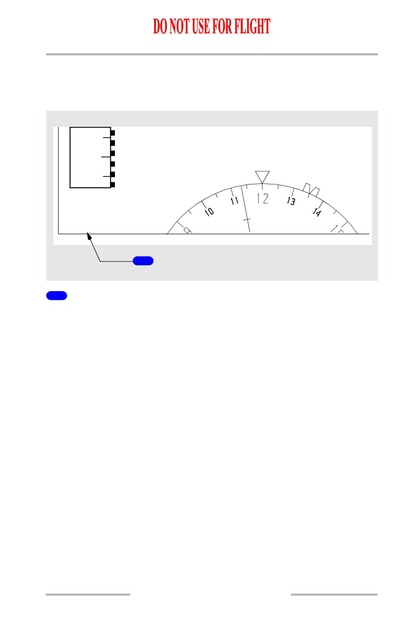
Note: The following annunciations occupy the same display location in the lower
left corner of the primary flight display.
80
CDS
MAINT
135
H
MAG
1
1
Display System Annunciations
DSPLY SOURCE (amber) - A single DEU has been selected, either manually or
automatically, to drive all six display units.
• If the DEU fails on the same side as the engaged autopilot during climb or
descent -
[Option - Integrated cue command bar]
• the flight directors are removed from both pilots’ displays. The flight
directors reappear at ALT ACQ
• the pitch mode reverts to CWS pitch
• the autopilot remains engaged.
• If the DEU fails on the same side as the engaged autopilot during level
flight -
• climb or descent to a new MCP altitude is not possible in LVL CHG,
VNAV, or V/S modes with the autopilot engaged.
• If the DEU fails on the opposite side as the engaged autopilot or while in
manual F/D mode during climb or descent -
[Option - Integrated cue command bar]
• the flight director is removed from the pilot’s display on the failed side
until ALT ACQ
• climb or descent is possible in LVL CHG, VNAV or V/S modes with
the autopilot engaged.
• If the DEU fails on the same side as the engaged autopilot in the
APPROACH mode -
10.11.33
Flight Instruments, Displays -
PFD/ND - Displays
Boeing 737 Operations Manual
[Option - Integrated cue command bar]
• the flight directors are removed from the pilot’s display on the failed
side.
[Option - With CDS Block 99 software upgrade or higher]
CDS MAINT (white) - A dispatchable CDS fault has occurred. Displayed on the
ground only, prior to start of the second engine.
[Option - Without CDS Block 99 software upgrade or higher]
CDS MAINT (white) - A non-dispatchable CDS fault has occurred. Displayed on
the ground only, prior to start of the second engine.
CDS FAULT (amber) - A non-dispatchable CDS fault has occurred. Displayed
on the ground only, prior to start of the second engine.
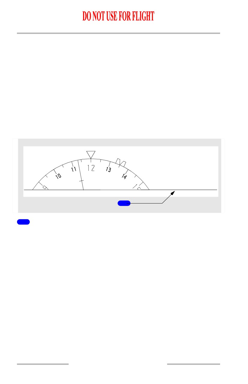
Instrument Switch Annunciation
135
H
MAG
INSTR SWITCH
1
1
INSTR SWITCH Annunciation (amber)
Indicates both the Captain’s and First Officer’s displays are using the same source
of IRU data.
Displayed when the IRS switch on the overhead panel is not in the NORMAL
position.
10.11.34
Flight Instruments, Displays -
PFD/ND - Displays
Boeing 737 Operations Manual
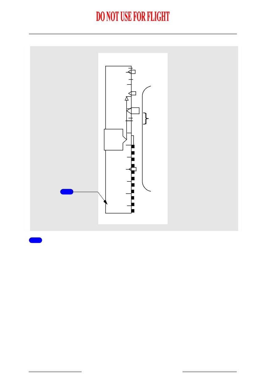
Airspeed Disagree Alert
148
180
1
160
R
140
V1
1245
100
1
80
IAS
DISAGREE
1
Airspeed Disagree Alert (amber)
Indicates the Captain’s and F/O’s airspeed indications disagree by more than 5
knots for 5 continuous seconds.
10.11.35