Boeing 737 - 600/700/800/900. Operations Manual (1997 year) - page 43
Flight Instruments, Displays -
EFIS/Map - Controls and
Indicators
Boeing 737 Operations Manual
5
Lateral Deviation Source Annunciation (green)
Identifies the selected navigation source as VOR or ILS.
6
Selected Heading Bug (magenta)
Indicates the heading selected on the mode control panel. If the selected heading
exceeds the display range, the bug parks on the side of the compass rose in the
direction of the shorter turn to the heading.
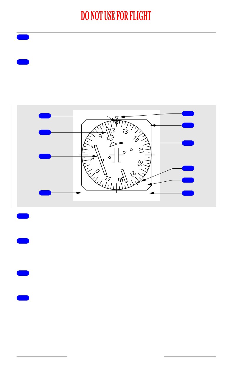
Horizontal Situation Indicator - Compact Display
5
1
VOR
6
2
7
3
8
9
TO
4
HDG MAG
116.80
10
1
Drift Angle Pointer (white)
Indicates current drift angle or track.
2
Selected Course Pointer (white)
Indicates the course set on the mode control panel. Set by the related mode control
panel course selector.
3
Course Deviation Indicator (magenta)
Indicates deviation from the selected localizer or VOR course.
4
Magnetic/True Heading Annunciation (green)
Indicates the HSI reference:
• HDG MAG (green) indicates display is oriented relative to magnetic
north
• TRU HDG (green) indicates display is oriented relative to true north; a
white box is displayed continuously around TRU HDG
10.10.28
Flight Instruments, Displays -
EFIS/Map - Controls and
Indicators
Boeing 737 Operations Manual
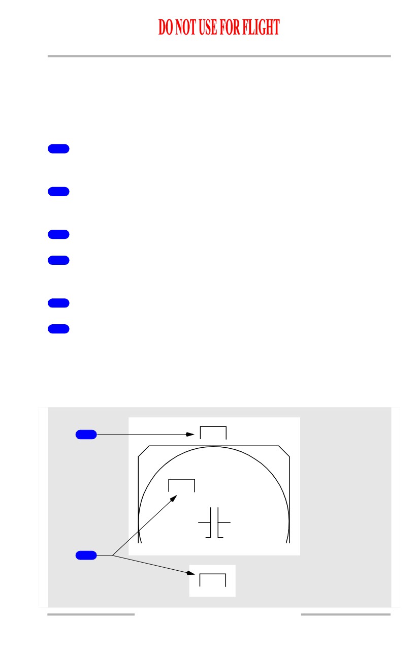
• transition from TRU HDG to HDG MAG results in a green box around
HDG MAG for 10 seconds
• when TRU HDG is displayed and the airplane descends more than 2000
feet at a descent rate greater than -800 feet per minute, an amber box is
drawn around TRU HDG; the box flashes for 10 seconds, then turns
steady amber.
5
Heading Pointer (white)
Indicates current heading.
6
Lateral Deviation Source Annunciation (green)
Identifies the selected navigation source as VOR or ILS.
7
TO/FROM Pointer (white)
8
Selected Heading Bug (magenta)
Indicates the heading selected on the mode control panel.
9
TO/FROM Annunciation (white)
10
Frequency Display (green)
Indicates selected navigation radio frequency.
Horizontal Situation Indicator Failure Flags
The flags replace the horizontal situation indicator displays to indicate source
system failure or lack of computed data.
1
HDG
VOR
2
LOC
10.10.29
Flight Instruments, Displays -
EFIS/Map - Controls and
Indicators
Boeing 737 Operations Manual
1
Heading Failure Flag (amber)
The heading source has failed. The compass rose is removed.
2
VOR/LOC Failure Flag (amber)
The airplane navigation data source has failed.
Navigation Displays -
Radio Distance Magnetic Indicator (RDMI)
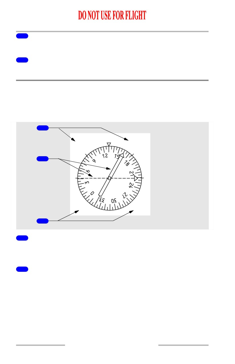
Radio Distance Magnetic Indicator - General
The RDMI provides the same information as a conventional RDMI.
1
10.5
110
DME1
DME2
2
VOR1
VOR2
3
1
DME Indications (white)
Displayed if DME information is available from the navigation aid tuned in the
VHF navigation control panel.
2
Bearing Pointers (VOR source-green, ADF source-cyan)
• narrow pointer uses signals from the VHF NAV receiver No. 1 or ADF
receiver No. 1
[Option - 2 ADF receivers]
• wide pointer uses signals from the VHF NAV receiver No. 2 or ADF
receiver No. 2.
10.10.30
Flight Instruments, Displays -
EFIS/Map - Controls and
Indicators
Boeing 737 Operations Manual
3
Bearing Source Indications (VOR source-green, ADF source-cyan)
• indicates “OFF” (white) if related VOR/ADF switch on the EFIS control
panel is in the OFF position
[Option - 2 ADF receivers]
• bearing source indicator No. 2 displays “INOP” (white) if the No. 2
VOR/ADF switch is in the ADF position and the No. 2 ADF receiver is
not installed.
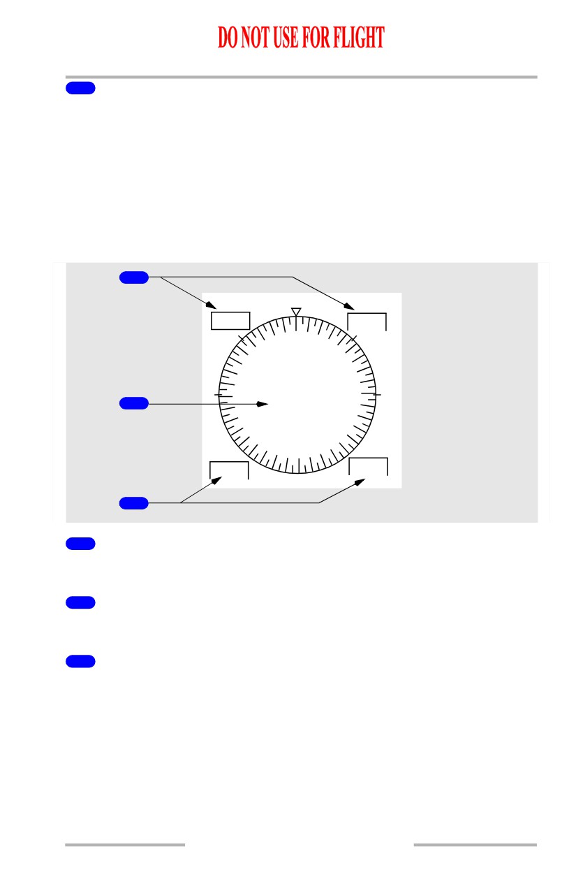
Radio Distance Magnetic Indicator Failure Flags
The flags replace the RDMI displays to indicate source system failure.
1
DME1
DME2
2
VOR1
VOR2
3
1
DME Failure Flags (amber)
The DME system has failed.
2
Heading Failure
The heading display is removed if heading information has failed.
3
VOR, ADF Failure Flags (amber)
The selected VOR or ADF information is invalid.
10.10.31
Flight Instruments, Displays -
EFIS/Map - Controls and
Indicators
Boeing 737 Operations Manual
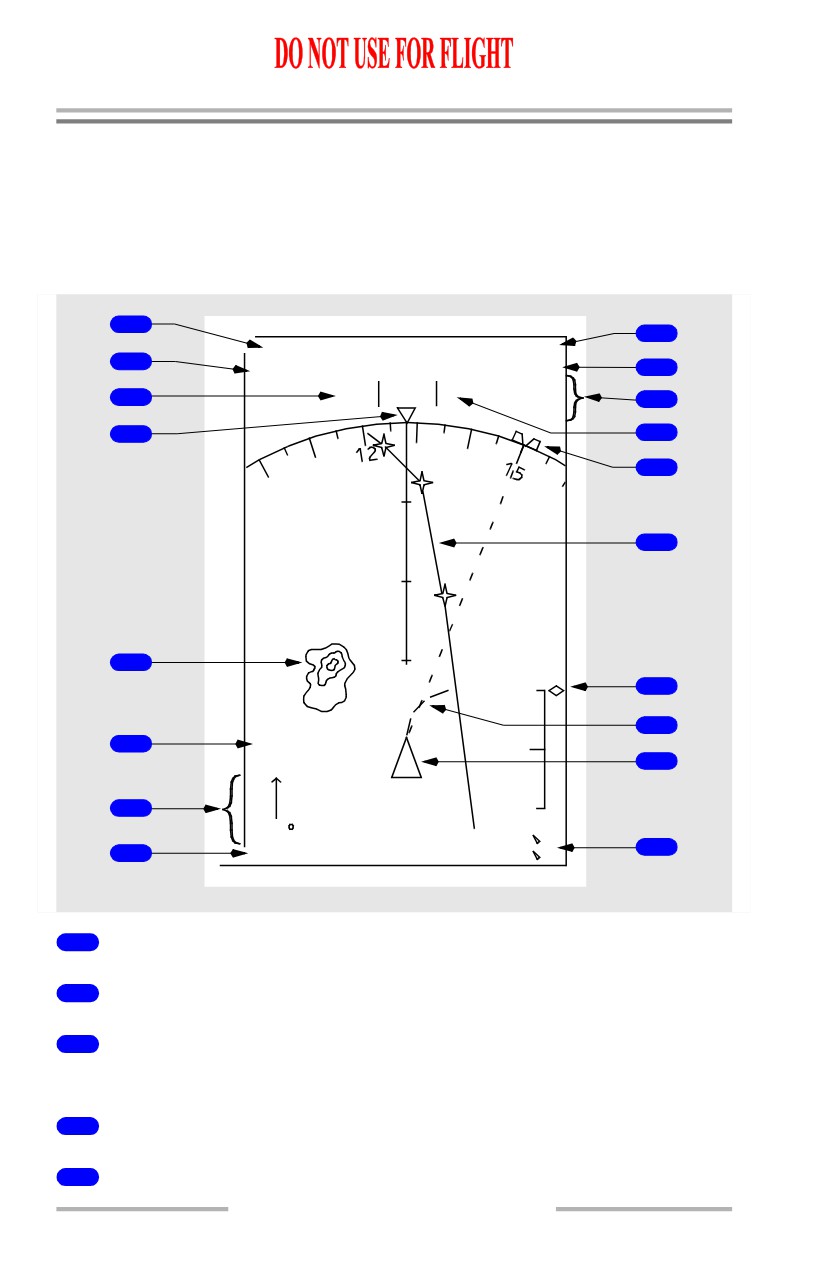
Navigation Displays - MAP Mode
Note: Refer to section 40 of this chapter for a detailed explanation of the
navigation symbology shown on the following pages.
Expanded MAP Mode
[Option - Heading-up display, weather radar range marks, single FMC]
1
9
36.9 NM
0205.0 Z
2
TAS
296
GS320
10
VAR/WX+T
3
HDG
128
M
11
+15
4
12
WPT01
13
LOATH
14
40
WINLO
5
2100
15
ARPT
16
6
WPT
STA
17
7
308
/24
12.3
R
18
8
FMC
12.3
L
1
Distance to Next Active Waypoint
2
True Airspeed
3
Current Heading
[Option - Heading-up display]
4
Heading Pointer
5
Weather Radar Returns
10.10.32
Flight Instruments, Displays -
EFIS/Map - Controls and
Indicators
Boeing 737 Operations Manual
6
MAP Options
7
Wind Direction and Speed
8
MAP Source Annunciation
9
Estimated Time of Arrival at Next Active Waypoint
10
Groundspeed
11
Weather Radar Annunciations
12
Magnetic/True Reference
13
Selected Heading Bug
14
Active LNAV Route
15
Vertical Deviation Scale and Pointer
16
Position Trend Vector
17
Airplane Symbol
18
Position Difference Display
10.10.33
Flight Instruments, Displays -
EFIS/Map - Controls and
Indicators
Boeing 737 Operations Manual
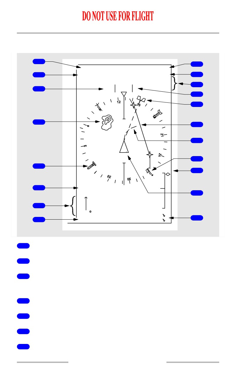
Center MAP Mode
[Option - Heading-up display, full-time ADF, 2 ADF receivers, single FMC]
1
8
36.9 NM
0205.0 Z
2
TAS
296
GS320
9
VAR/WX+T
+15
10
3
HDG
128
M
11
12
WINLO
20
4
13
14
OLM01
18
20
19
2100
15
ARPT
WPT
5
STA
16
6
308
/24
12.3
R
17
7
FMC
12.3
L
1
Distance to Next Active Waypoint
2
True Airspeed
3
Current Heading
[Option - Heading-up display]
4
Weather Radar Returns
5
MAP Options
6
Wind Direction and Speed
7
MAP Source Annunciation
10.10.34
Flight Instruments, Displays -
EFIS/Map - Controls and
Indicators
Boeing 737 Operations Manual
8
Estimated Time of Arrival at Next Active Waypoint
9
Groundspeed
10
Weather Radar Annunciations
11
Magnetic/True Reference
12
Selected Heading Bug
13
Active Route
14
Position Trend Vector
15
Vertical Deviation Scale and Pointer
16
Airplane Symbol
17
Position Difference Display
18
ADF1 Bearing Pointer
[Option - Full-time ADF]
19
ADF2 Bearing Pointer
[Option - Full-time ADF, 2 ADF receivers]
10.10.35
Flight Instruments, Displays -
EFIS/Map - Controls and
Indicators
Boeing 737 Operations Manual
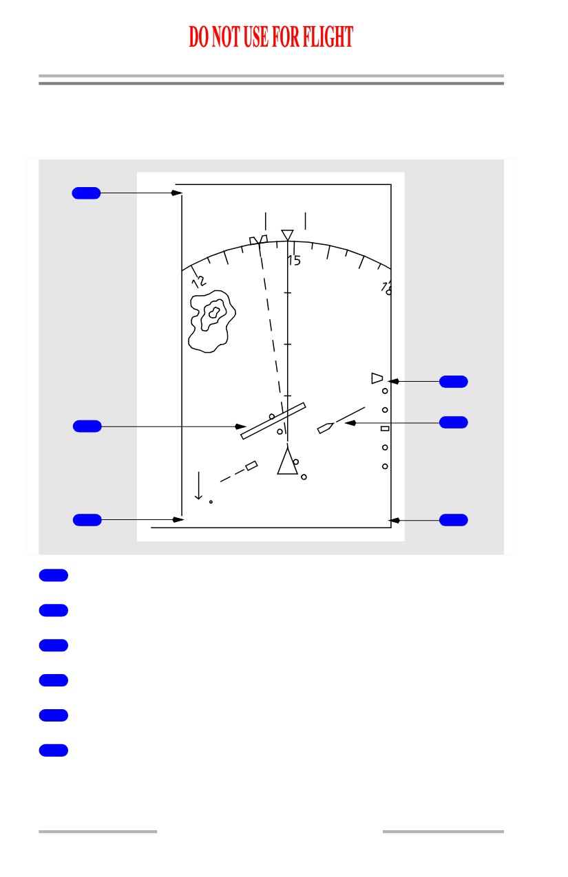
Navigation Displays - Approach Mode
Expanded Approach Mode
[Option - Weather radar range marks]
1
DME 10.2
TAS
196
GS181
VAR/WX+T
HDG
148
M
+
15
20
4
5
2
150 /15
3
ILS 1
109.90
6
1
Reference ILS DME
2
Localizer Deviation Indication and Scale
3
Reference ILS Receiver
4
Glide Slope Pointer and Scale
5
Selected Course Pointer
6
Reference ILS Frequency
10.10.36
Flight Instruments, Displays -
EFIS/Map - Controls and
Indicators
Boeing 737 Operations Manual
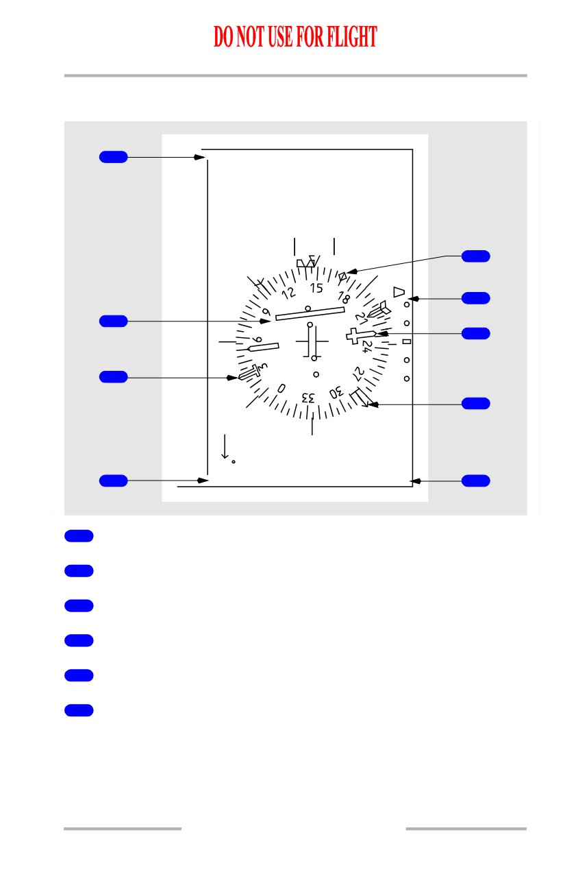
Center Approach Mode
[Option - Dual ADF]
1
DME 10.2
TAS 196
GS181
HDG
148
M
4
5
2
6
9
8
150 /15
3
ILS 1
109.90
7
1
Reference ILS DME
2
Localizer Deviation Indication and Scale
3
Reference ILS Receiver
4
Drift Angle Pointer
5
Glide Slope Pointer and Scale
6
Selected Course Pointer
10.10.37
Flight Instruments, Displays -
EFIS/Map - Controls and
Indicators
Boeing 737 Operations Manual
7
Reference ILS Frequency
8
ADF1 Bearing Pointer
9
ADF2 Bearing Pointer
[Option - Dual ADF]
10.10.38
Flight Instruments, Displays -
EFIS/Map - Controls and
Indicators
Boeing 737 Operations Manual
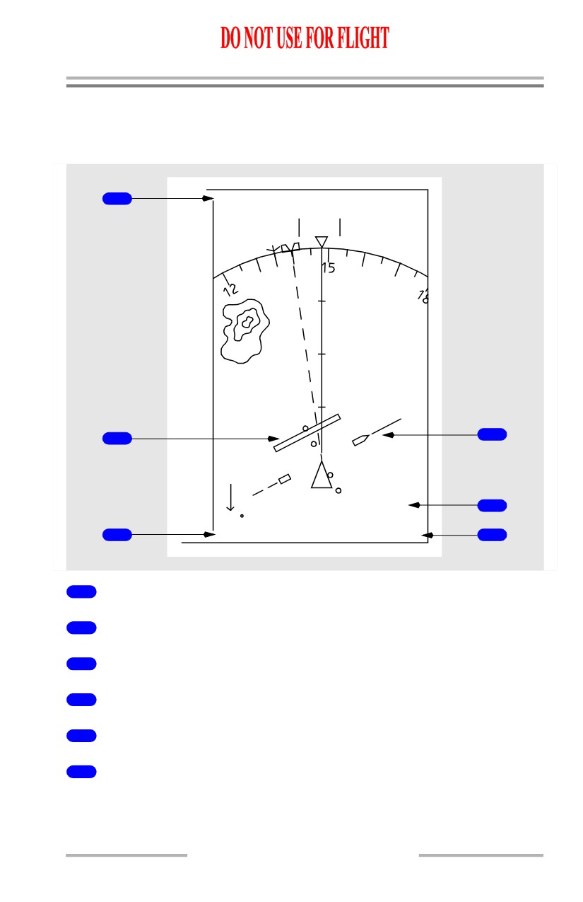
Navigation Displays - VOR Mode
Expanded VOR Mode
[Option - Weather radar range marks]
1
DME 30.5
TAS
296
GS281
VAR/WX+T
HDG
148
M
+
15
20
4
2
FROM
5
150 /15
3
VOR 1
116.60
6
1
Reference VOR DME
2
Lateral Deviation Indication and Scale
3
Reference VOR Receiver
4
Selected Course Pointer
5
TO/FROM Indication
6
Reference VOR Frequency
10.10.39
Flight Instruments, Displays -
EFIS/Map - Controls and
Indicators
Boeing 737 Operations Manual
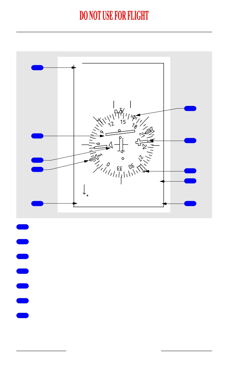
Center VOR Mode
[Option - Dual ADF]
1
DME10.2
TAS 196
GS181
HDG
148
M
5
2
6
3
10
9
FROM
7
150 /15
4
VOR 1
116.60
8
1
Reference VOR DME
2
Lateral Deviation Indication and Scale
3
TO/FROM Pointer
4
Reference VOR Receiver
5
Drift Angle Pointer
6
Selected Course Pointer
7
TO/FROM Indication
10.10.40
Flight Instruments, Displays -
EFIS/Map - Controls and
Indicators
Boeing 737 Operations Manual
8
Reference VOR Frequency
9
ADF1 Bearing Pointer
10
ADF2 Bearing Pointer
[Option - Dual ADF]
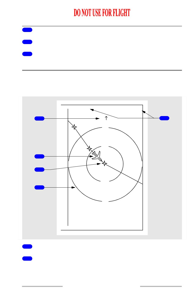
Navigation Displays - Plan Mode
Plan Mode
[Option - Single FMC]
67.3 NM
0737.0 Z
TAS 280
GS304
1
N
5
FEDEL
40
CECHI
20
2
CELES
W
E
3
20
4
40
S
FMC
1
True North Up Arrow
2
Airplane Symbol
Denotes current position and true heading. Symbol does not display north of 82N
latitude or south of 82S latitude.
10.10.41
Flight Instruments, Displays -
EFIS/Map - Controls and
Indicators
Boeing 737 Operations Manual
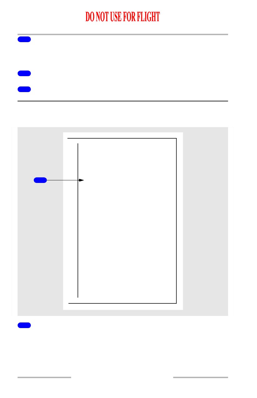
3
Center Waypoint
The waypoint located at the display center is identified as CTR on the CDU RTE
LEGS page.
4
Range Circle
5
Active Waypoint Information
Navigation Displays - Advisory Messages
Mode/Frequency Disagree Annunciation
1
EFIS MODE/NAV FREQ DISAGREE
1
Mode/Frequency Disagree Annunciation (amber)
Indicates APP is selected with a VOR frequency tuned, or VOR is selected with
an ILS frequency tuned.
• the annunciation only applies to an on-side comparison of the EFIS
control panel mode and tuned VOR/ILS frequency
• applicable to expanded and center APP and VOR modes
10.10.42
Flight Instruments, Displays -
EFIS/Map - Controls and
Indicators
Boeing 737 Operations Manual
• dashes displayed on DME display and ILS/VOR frequency display
• localizer deviation bar, VOR course deviation bar, and glide slope pointer
(for APP mode) are not displayed.
Navigation Advisory Messages
UNABLE REQD NAV PERF-RNP
3
MAP RANGE DISAGREE
1
WXR RANGE DISAGREE
MAP/WXR RANGE DISAGREE
2
EXCESS DATA
1
Range Disagreement Annunciations (amber)
MAP RANGE DISAGREE - Indicates selected range on the EFIS control panel
is different than the MAP display range.
WXR RANGE DISAGREE - Indicates selected range on the EFIS control panel
is different than the WXR display range.
MAP/WXR RANGE DISAGREE - Indicates selected range on the EFIS control
panel is different than the MAP and WXR display ranges.
2
EXCESS DATA Annunciation (amber)
The amount of data sent to the navigation display exceeds the display capability.
10.10.43
Flight Instruments, Displays -
EFIS/Map - Controls and
Indicators
Boeing 737 Operations Manual
3
Nav Advisory Message (amber)
UNABLE REQD NAV PERF-RNP - Displayed in MAP or Center MAP during
approach. Refer to Chapter 11 section 60, FMC Messages.
TCAS Messages
TCAS
1
FAIL
2
OFFSCALE
TRAFFIC
3
TA 6.8 -11
4
1
TCAS Annunciations
TFC (cyan) - TFC selected on the EFIS control panel in Expanded MAP, Center
MAP, Expanded APP or Expanded VOR modes.
TCAS TEST (cyan) - TCAS in test mode.
TCAS FAIL (amber) - TCAS has failed.
TA ONLY (cyan) - TCAS TA only mode.
TCAS OFF (amber) - TCAS off.
2
OFFSCALE (red or amber)
TA (amber) or RA (red) is beyond the display range.
10.10.44
Flight Instruments, Displays -
EFIS/Map - Controls and
Indicators
Boeing 737 Operations Manual
3
TRAFFIC (red or amber)
Displayed during a TA (amber) or RA (red) condition.
4
No Bearing Message (red or amber)
Displayed when no bearing information is available for traffic.
Look-Ahead Terrain Messages (GPWS)
TERR TEST
3
TERR
TERR
FAIL
TERR
1
POS
TERR
INHIBIT
TERR RANGE DISAGREE
2
MAP/TERR RANGE DISAGREE
1
Terrain Status Annunciation (amber)
TERR FAIL - Look-ahead terrain alerting and display have failed.
TERR POS - Look-ahead terrain alerting and display unavailable due to position
uncertainty.
TERR INHIBIT - GPWS terrain inhibit switch in TERR INHIBIT position.
10.10.45
Flight Instruments, Displays -
EFIS/Map - Controls and
Indicators
Boeing 737 Operations Manual
2
Terrain Range Status Annunciation (amber)
TERR RANGE DISAGREE -
• terrain display enabled, and
• terrain output range disagrees with selected EFIS control panel range.
MAP/TERR RANGE DISAGREE -
• terrain display enabled, and
• terrain output range disagrees with selected EFIS control panel range, and
• map display output range disagrees with selected EFIS control panel
range.
3
Terrain Mode Annunciation (cyan)
TERR TEST - GPWS is operating in self-test mode.
TERR - Terrain display enabled (manual or automatic display).
Predictive Windshear System (PWS) Message
PWS
1
FAIL
10.10.46
Flight Instruments, Displays -
EFIS/Map - Controls and
Indicators
Boeing 737 Operations Manual
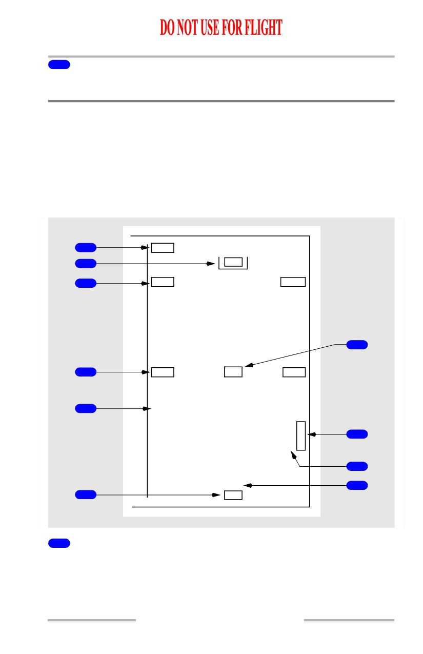
1
PWS FAIL Annunciation (amber)
Predictive windshear alerting and display have failed.
Navigation Displays -
Failure Indications and Flags
Dashes replace numbers if there is no computed information. Failure flags replace
symbols or failure messages are displayed, as appropriate.
Failure Flags - Expanded MAP, Center MAP, Expanded APP,
Expanded VOR Modes
[Option - Heading-up display, dual ADF]
1
DME
2
HDG
3
ADF1
ADF2
7
4
VOR1
MAP
VOR2
WXR
5
FAIL
G
V
/
T
8
S
K
9
LOC
10
6
VOR
1
DME Failure Flag (APP and VOR modes)
DME display has failed.
10.10.47