Boeing 737 - 600/700/800/900. Operations Manual (1997 year) - page 44
Flight Instruments, Displays -
EFIS/Map - Controls and
Indicators
Boeing 737 Operations Manual
2
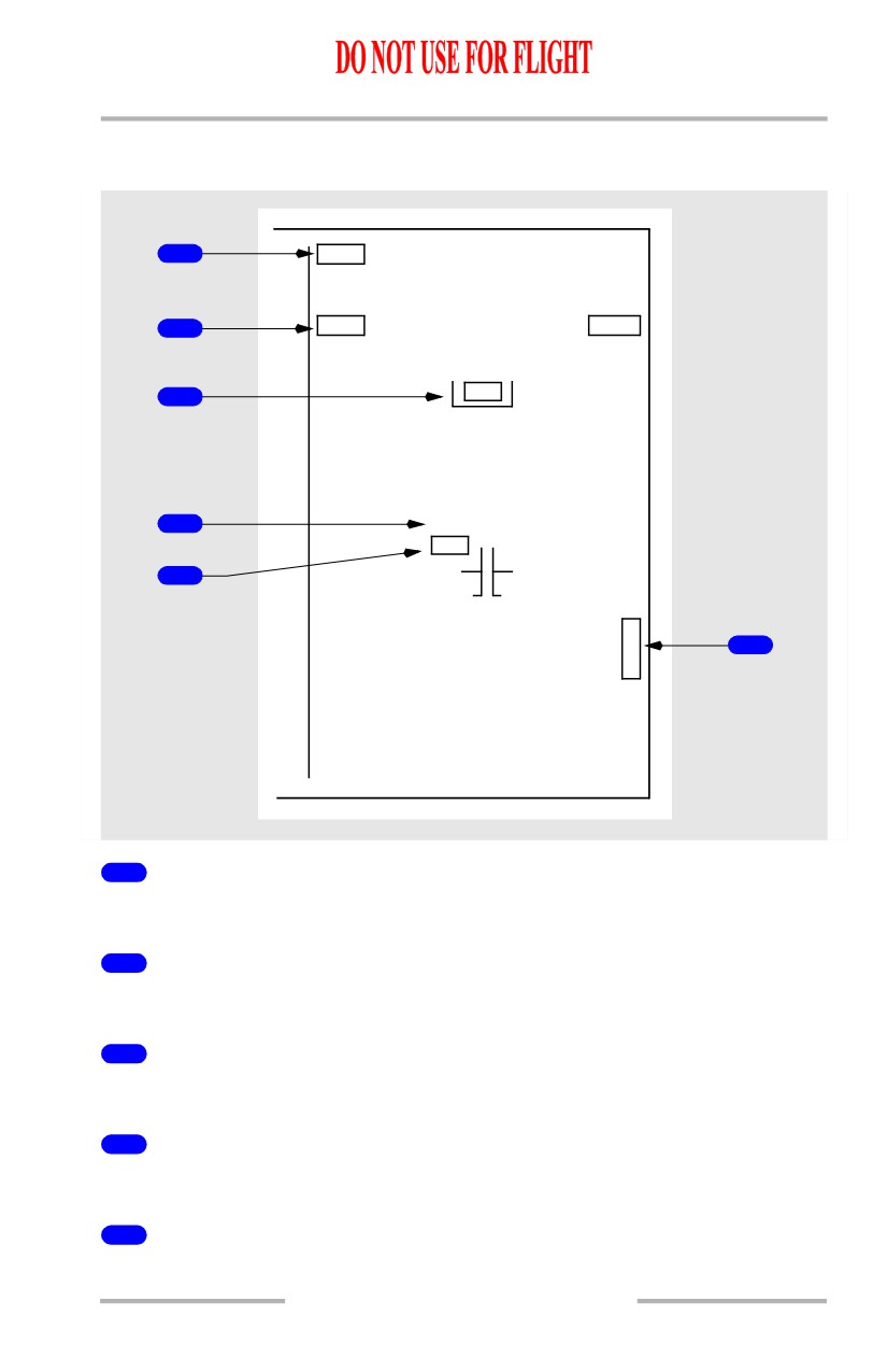
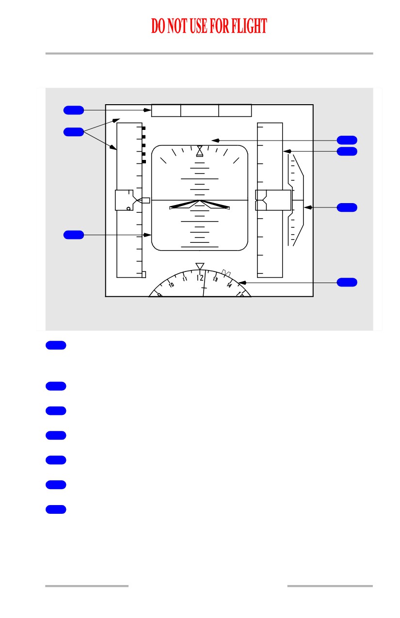
Heading Failure Flag (MAP, APP and VOR modes)
[Option - Heading-up display]
Heading display has failed.
3
ADF Failure Flag (MAP, APP and VOR modes)
[Option - Full time ADF in MAP mode]
ADF display has failed.
4
VOR Failure Flag (MAP modes)
EFIS control panel POS switch selected and VOR display failed.
5
Weather Radar Annunciations (MAP, APP and VOR modes)
WXR FAIL - Weather radar has failed. No weather data are displayed.
WXR WEAK - Weather radar calibration fault.
WXR ATT - Attitude stabilization for antenna has been lost.
WXR STAB - Antenna stabilization is off.
WXR DSP - Display unit cooling has been lost or an overheat condition has
occurred. Weather radar display is blanked.
6
VOR Failure Flag (VOR modes)
VOR display has failed.
7
MAP Failure Flag (MAP modes)
The related FMC generated map display has failed.
8
Vertical Track Failure Flag (MAP modes)
FMC vertical track data are invalid.
9
ILS Glide Slope Failure Flag (APP modes)
ILS glide slope display has failed.
10
ILS Localizer Failure Flag (APP modes)
ILS localizer display has failed.
10.10.48
Flight Instruments, Displays -
EFIS/Map - Controls and
Indicators
Boeing 737 Operations Manual
Failure Flags - Center APP and Center VOR Modes
[Option - Dual ADF]
1
DME
2
ADF1
ADF2
3
HDG
4
LOC
VOR
5
G
/
6
S
1
DME Failure Flag (APP and VOR modes)
DME display has failed.
2
ADF Failure Flag (APP and VOR modes)
ADF display has failed.
3
Heading Failure Flag (APP and VOR modes)
Heading display has failed.
4
ILS Localizer Failure Flag (APP modes)
ILS localizer display has failed.
5
VOR Failure Flag (VOR modes)
VOR display has failed.
10.10.49
Flight Instruments, Displays -
EFIS/Map - Controls and
Indicators
Boeing 737 Operations Manual
6
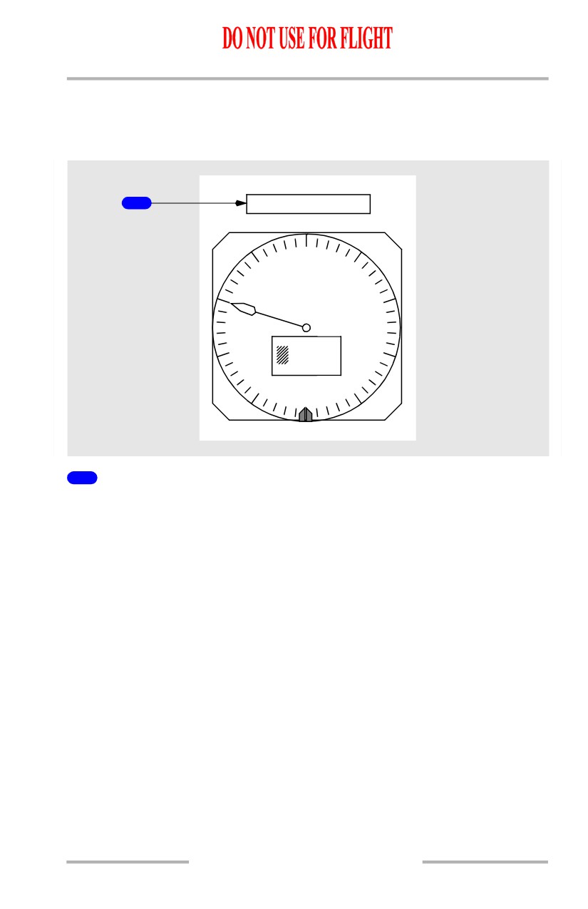
ILS Glide Slope Failure Flag (APP modes)
ILS glide slope display has failed.
Additional Flags and Annunciations
Displays Control Panel Annunciation
DISPLAYS
1
CONTROL PANEL
ALT
1
Displays Control Panel Annunciation (amber)
With the CONTROL PANEL select switch on the overhead panel in:
• BOTH ON 1 - left (Capt) EFIS control panel has failed
• NORMAL - corresponding EFIS control panel has failed
• BOTH ON 2 - right (F/O) EFIS control panel has failed.
Altitude information is removed.
10.10.50
Flight Instruments, Displays -
EFIS/Map - Controls and
Indicators
Boeing 737 Operations Manual
Display System Annunciations
Note: The following annunciations occupy the same display location above the
altimeter.
1
DSPLY SOURCE
0
9
1
29.92
IN.
8
2
7
3
0
800
80
6
4
5
1
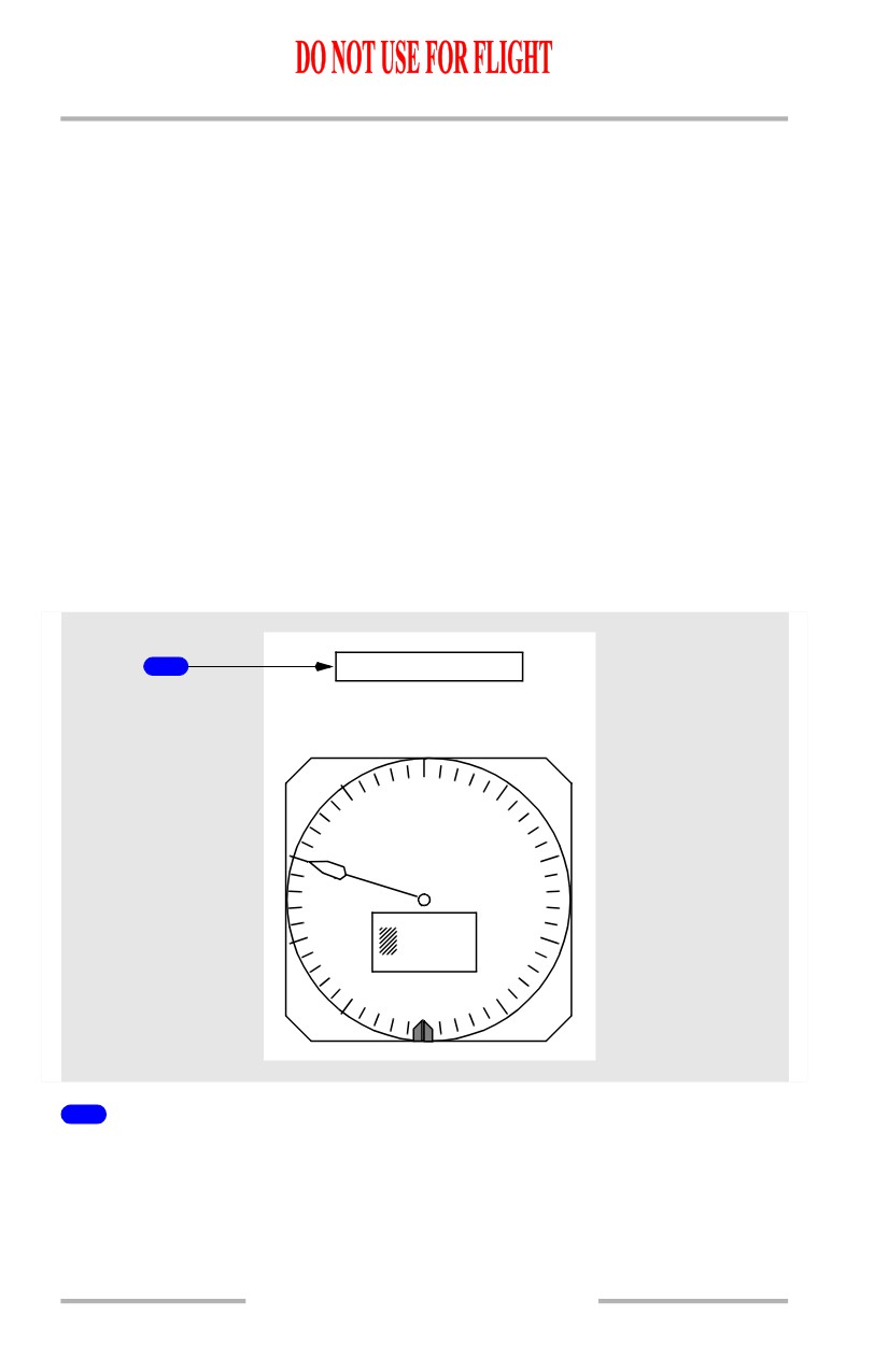
Display System Annunciations
DSPLY SOURCE (amber) - A single DEU has been selected, either manually or
automatically, to drive all six display units.
• If the DEU fails on the same side as the engaged autopilot during climb or
descent -
[Option - Split axis command bars]
• the flight director pitch command bars are removed from both pilots’
displays. The pitch command bars reappear at ALT ACQ
• the pitch mode reverts to CWS pitch
• the autopilot remains engaged.
• If the DEU fails on the same side as the engaged autopilot during level
flight -
• climb or descent to a new MCP altitude is not possible in LVL CHG,
VNAV, or V/S modes with the autopilot engaged.
• If the DEU fails on the opposite side as the engaged autopilot or while in
manual F/D mode during climb or descent -
[Option - Split axis command bars]
• the flight director pitch command bar is removed from the pilot’s
display on the failed side until ALT ACQ
10.10.51
Flight Instruments, Displays -
EFIS/Map - Controls and
Indicators
Boeing 737 Operations Manual
• climb or descent is possible in LVL CHG, VNAV or V/S modes with
the autopilot engaged.
• If the DEU fails on the same side as the engaged autopilot in the
APPROACH mode -
[Option - Split axis command bars]
• the flight director pitch and roll command bars are removed from the
pilot’s display on the failed side.
[Option - With CDS Block 99 software upgrade]
CDS MAINT (white) - A dispatchable CDS fault has occurred. Displayed on the
ground only, prior to start of the second engine.
[Option - Without CDS Block 99 software upgrade]
CDS MAINT (white) - A non-dispatchable CDS fault has occurred. Displayed on
the ground only, prior to start of the second engine.
CDS FAULT (amber) - A non-dispatchable CDS fault has occurred. Displayed
on the ground only, prior to start of the second engine.
Instrument Switch Annunciation
1
INSTR SWITCH
0
9
1
29.92
IN.
8
2
7
3
800
80
6
4
5
1
INSTR SWITCH Annunciation (amber)
Indicates both the Captain’s and First Officer’s displays are using the same source
of IRU data. Displayed when the IRS switch on the overhead panel is not in the
NORMAL position.
10.10.52
Boeing 737 Operations Manual
Flight Instruments, Displays
Chapter 10
PFD/ND - Displays
Section 11
PFD/ND Display System - Overview
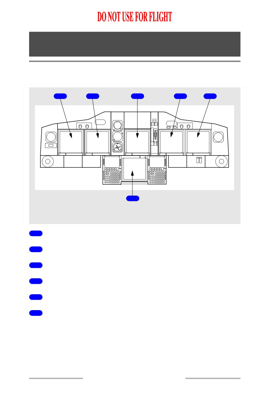
Display Units
1
2
3
4
5
6
LEFT, CENTER and RIGHT
FORWARD PANEL
1
Captain Outboard Display Unit
2
Captain Inboard Display Unit
3
Upper Display Unit
4
First Officer Inboard Display Unit
5
First Officer Outboard Display Unit
6
Lower Display Unit
10.11.1
Flight Instruments, Displays -
PFD/ND - Displays
Boeing 737 Operations Manual
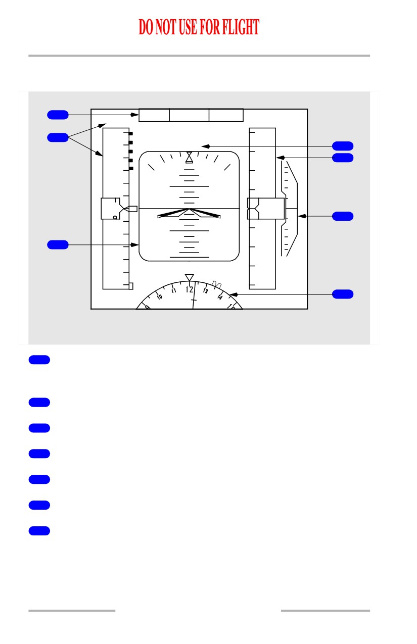
Captain Outboard Display
[Option - Integrated cue command bar]
1
N1
LNAV
VNAV PTH
.82
31000
360
31
400
2
CMD
4
340
5
6
31
200
2
320
10
10
1
20
300
31
000
80
6
10
10
1
280
3
30
800
2
6
260
240
30
600
7
.820
STD
135 H
MAG
LEFT FORWARD PANEL
1
Flight Mode Annunciator
Refer to Chapter 4, Automatic Flight
2
Airspeed/Mach Indications
3
Attitude Indications
4
Autopilot, Flight Director System Status
5
Altitude Indications
6
Vertical Speed Indications
7
Heading/Track Indications
10.11.2
Flight Instruments, Displays -
PFD/ND - Displays
Boeing 737 Operations Manual
Captain Inboard Display
[Option - Track-up display, dual FMC]
1
1
2
FMC L
LEFT FORWARD PANEL
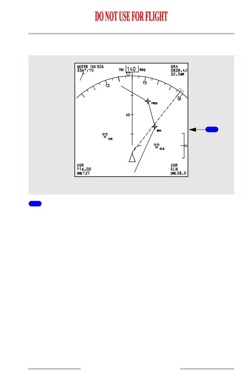
1
Navigation Display
Displays map, approach, VOR, or plan modes as selected on the EFIS control
panel.
10.11.3
Flight Instruments, Displays -
PFD/ND - Displays
Boeing 737 Operations Manual
First Officer Inboard Display
[Option - Track-up display, dual FMC]
1
1
2
FMC R
RIGHT FORWARD PANEL
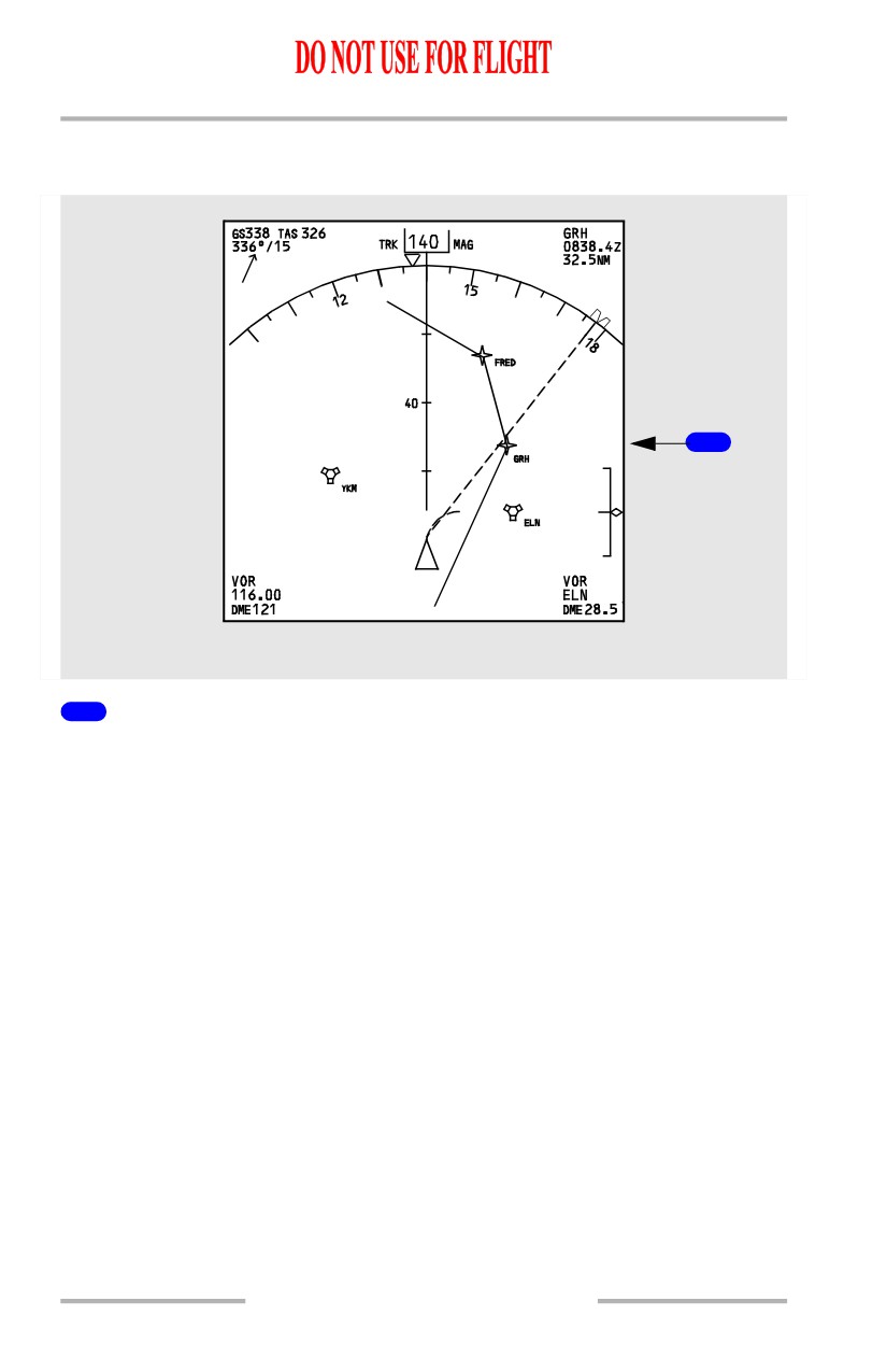
1
Navigation Display
Displays map, approach, VOR, or plan modes as selected on the EFIS control
panel.
10.11.4
Flight Instruments, Displays -
PFD/ND - Displays
Boeing 737 Operations Manual
First Officer Outboard Display
[Option - Integrated cue command bar]
1
N1
LNAV
VNAV PTH
.82
31000
360
31
400
2
CMD
4
340
5
6
31
200
2
320
10
10
1
20
300
31
000
80
6
10
10
1
280
3
30
800
2
6
260
240
30
600
7
.820
STD
135 H
MAG
RIGHT FORWARD PANEL
1
Flight Mode Annunciator
Refer to Chapter 4, Automatic Flight
2
Airspeed/Mach Indications
3
Attitude Indications
4
Autopilot, Flight Director System Status
5
Altitude Indications
6
Vertical Speed Indications
7
Heading/Track Indications
10.11.5
Flight Instruments, Displays -
PFD/ND - Displays
Boeing 737 Operations Manual
Primary Flight Display (PFD)-
PFD Airspeed Indications
PFD Airspeed Indications - General
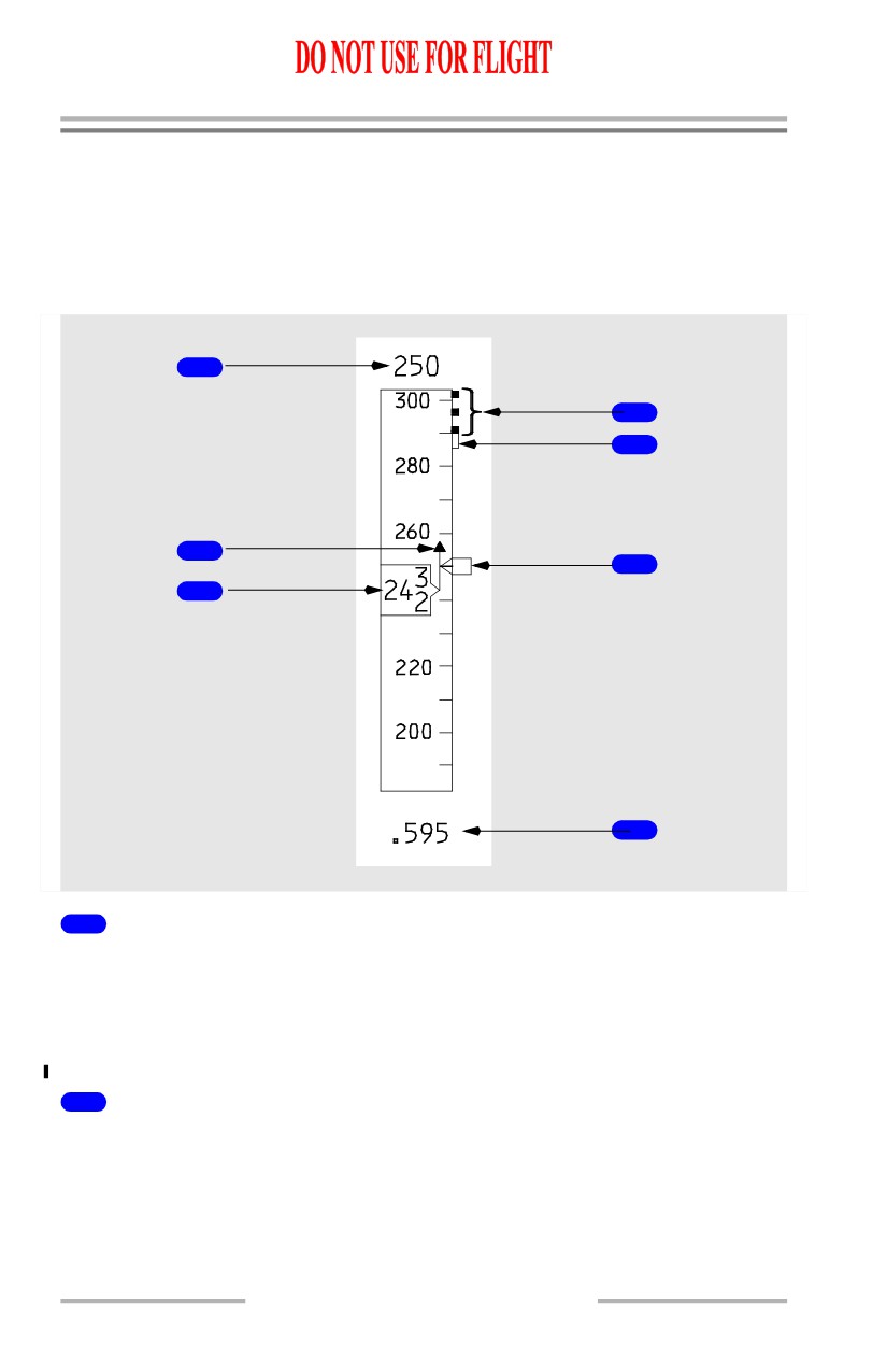
The PFD airspeed indication displays air data inertial reference system (ADIRS)
airspeed and other airspeed related information.
1
4
5
2
6
3
7
1
Selected Speed (magenta)
Displays target airspeed:
• indicates the airspeed manually selected in the IAS/MACH window
• indicates the FMC computed airspeed when the IAS/MACH window is
blank.
2
Speed Trend Vector (green)
Tip of arrow indicates predicted airspeed in the next 10 seconds based on the
current airspeed and acceleration.
10.11.6
Flight Instruments, Displays -
PFD/ND - Displays
Boeing 737 Operations Manual
3
Current Airspeed (white)
[Option - Low airspeed alert]
Indicates current calibrated airspeed in knots.
When current airspeed decreases into the minimum maneuver speed amber bar:
• airspeed readout box turns amber and flashes for 10 seconds
• box returns to white when airspeed is above minimum maneuver speed.
4
Maximum Speed (red and black)
Bottom of the bar indicates the maximum speed as limited by the lowest of the
following:
• Vmo/Mmo
• landing gear placard speed
• flap placard speed.
5
Maximum Maneuvering Speed (amber)
Bottom of the bar indicates the airspeed that provides a 0.3 g maneuver margin to
high speed buffet. May be displayed at high altitude with flaps up, at relatively
high gross weights.
6
Speed Bug (magenta)
Points to the airspeed:
• manually selected in the IAS/MACH window
• indicates the FMC computed airspeed when the IAS/MACH window is
blank.
When the selected speed is off scale, the bug is parked at the top or bottom of the
tape, with only one half bug visible.
7
Current Mach (white)
[Option - Without groundspeed displayed]
Indicates current Mach number:
• displays when airspeed is 0.40 Mach and above
• blanks when airspeed decreases below 0.40 Mach.
10.11.7
Flight Instruments, Displays -
PFD/ND - Displays
Boeing 737 Operations Manual
7
Current Mach/Groundspeed (white)
[Option - With groundspeed displayed]
Indicates current Mach or groundspeed:
• displays Mach when airspeed is 0.40 Mach and above
• displays groundspeed when airspeed decreases below 0.40 Mach
• when transitioning from Mach to groundspeed or from groundspeed to
Mach, a white box shows around the numeric value for 10 seconds.
PFD Airspeed Indications - Takeoff and Approach
[Option - 100 knot airspeed bug]
148
UP
200
180
1
1
2
180
3
160
7
5
R
160
4
140
V1
15
8
3
5
1
5
42
124
REF
9
6
120
100
11
100
80
VREF
10
132
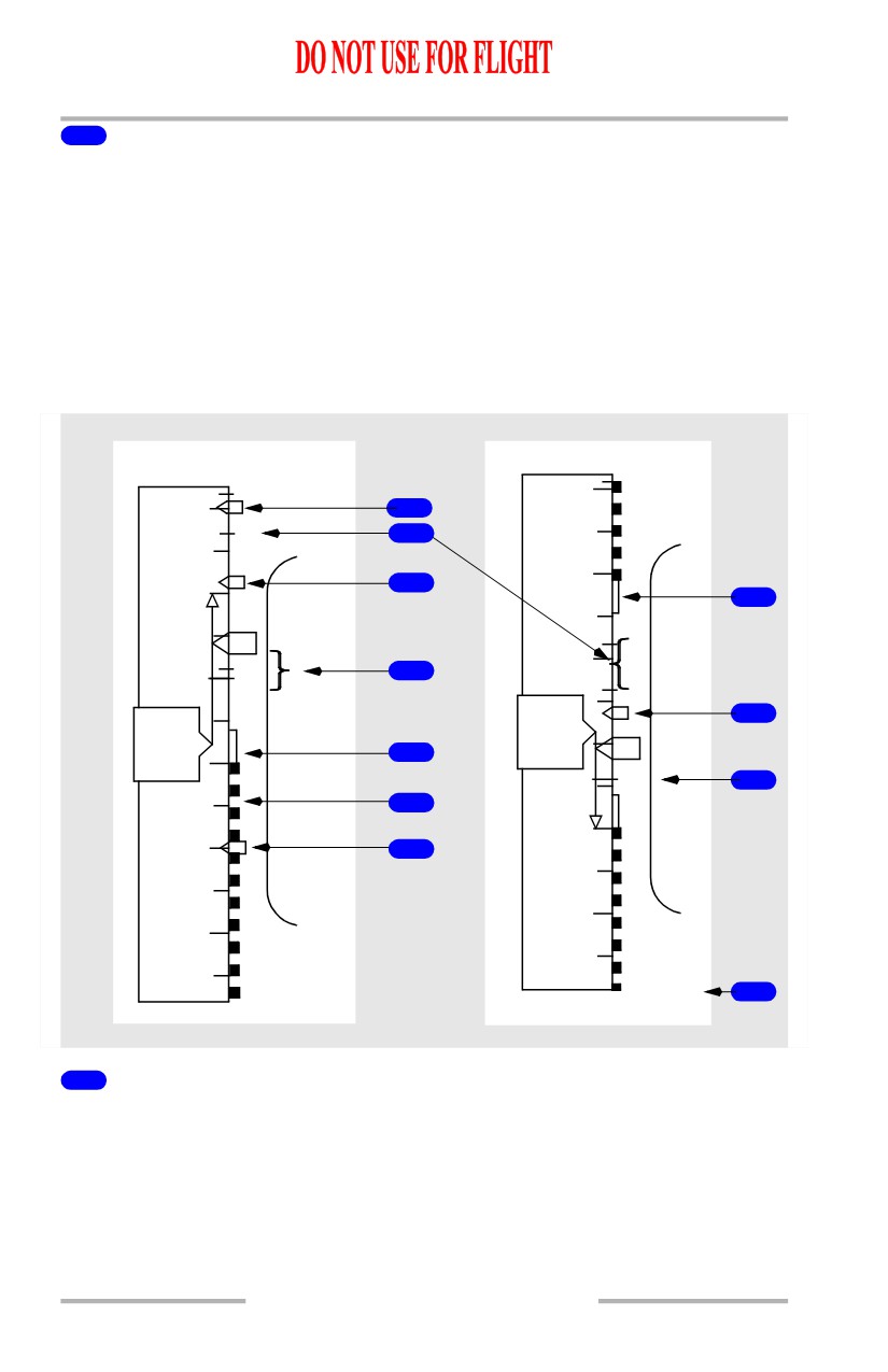
1
Bug 5 (white)
Displayed if speed reference selector on the engine display control panel is in the
bug 5 position or SET position and a value greater than 60 knots has been selected.
Not available if the speed reference selector is in the AUTO position.
10.11.8
Flight Instruments, Displays -
PFD/ND - Displays
Boeing 737 Operations Manual
2
Flaps Maneuvering Speeds (green)
Indicates flap maneuvering speed for the displayed flap position:
• displayed after gross weight is entered in the CDU or after takeoff gross
weight is set with the speed reference selector
• when the V2+15 bug is displayed for takeoff, the flap maneuvering speed
bug for the current flap setting is not displayed, except for flaps 1 takeoff.
• numbered flap maneuvering speed bugs are removed when flap lever is
moved to flaps 30 or 40
• flap bugs inhibited if less than VREF +4
• UP bug not displayed above approximately 20,000 feet altitude.
3
V2+15 (white)
Displayed for takeoff.
Removed when either of the following occurs:
• at first flap retraction
• when VREF is entered in the CDU.
4
Takeoff Reference Speeds (green)
Indicates V1 (decision speed) and VR (rotation speed) as selected on the CDU
TAKEOFF REF page (refer to Chapter 11, Flight Management, Navigation) or as
set with the speed reference selector on the engine display control panel:
• amber NO VSPD is displayed on the ground if V1 or VR is not selected
on the CDU or is not set with the speed reference selector
• displayed for takeoff when speed is greater than 80 knots
• removed at lift-off
• V1 speed is displayed at the top of airspeed indication when selected and
value is off scale.
[Option - V1 aural alert]
• V1 is automatically called out by voice aural.
Note: The Look Ahead Terrain Alerting system must be incorporated for the
automatic V1 aural callout to be functional.
5
Minimum Maneuver Speed (amber)
Top of bar indicates minimum maneuver speed.
Inhibited on takeoff until first flap retraction or valid VREF entered.
6
Minimum Speed (red and black)
Top of bar indicates the speed at which stick shaker occurs.
10.11.9
Flight Instruments, Displays -
PFD/ND - Displays
Boeing 737 Operations Manual
7
Maximum Maneuvering Speed (amber)
When flaps are not up, bottom of the bar indicates flap limit placard speed for the
next normal flap setting. The display logic is based on a normal flap setting
sequence of 1, 5, 15, 30. The bar is removed when the flap lever is moved to the
landing flap selected on the APPROACH REF page or when the flap lever is
moved to flaps 30 or 40.
[Option] - CDS Software Upgrade - Block point 2002
When flaps are not up, bottom of the bar indicates flap limit placard speed for the
next normal flap setting. The display logic is based on a normal flap setting
sequence of 1, 5, 15, 30. The bar is removed when the flaps reach the landing flap
selected on the APPROACH REF page or when the flaps reach flaps 40.
8
VREF+15 (white)
Displayed after selection of VREF.
9
Landing Reference Speed (green)
Indicates REF (reference speed) as selected on the CDU APPROACH REF page
(refer to Chapter 11, Flight Management, Navigation) or as set with the speed
reference selector on the engine display control panel.
REF speed is displayed at the bottom of airspeed indication when selected and
value is off scale.
10
Speed Reference Display (green)
Displayed if the airspeed and/or weight is entered via the speed reference selector
on the engine display control panel:
• on the ground, V1, VR, and takeoff gross weight may be selected; if
VREF is selected, INVALID ENTRY is displayed
• in flight, VREF and landing gross weight may be selected; if V1 or VR is
selected, INVALID ENTRY is displayed
• removed when the speed reference selector is moved to the SET position.
11
100 Knot Airspeed Bug (white)
[Option - 100 knot airspeed bug]
Indicates 100 knots:
• displayed automatically during preflight
• removed at first flap retraction or when VREF is entered.
10.11.10
Flight Instruments, Displays -
PFD/ND - Displays
Boeing 737 Operations Manual
PFD Angle of Attack (AOA) Indications
[Option]
Angle of Attack Indications - General
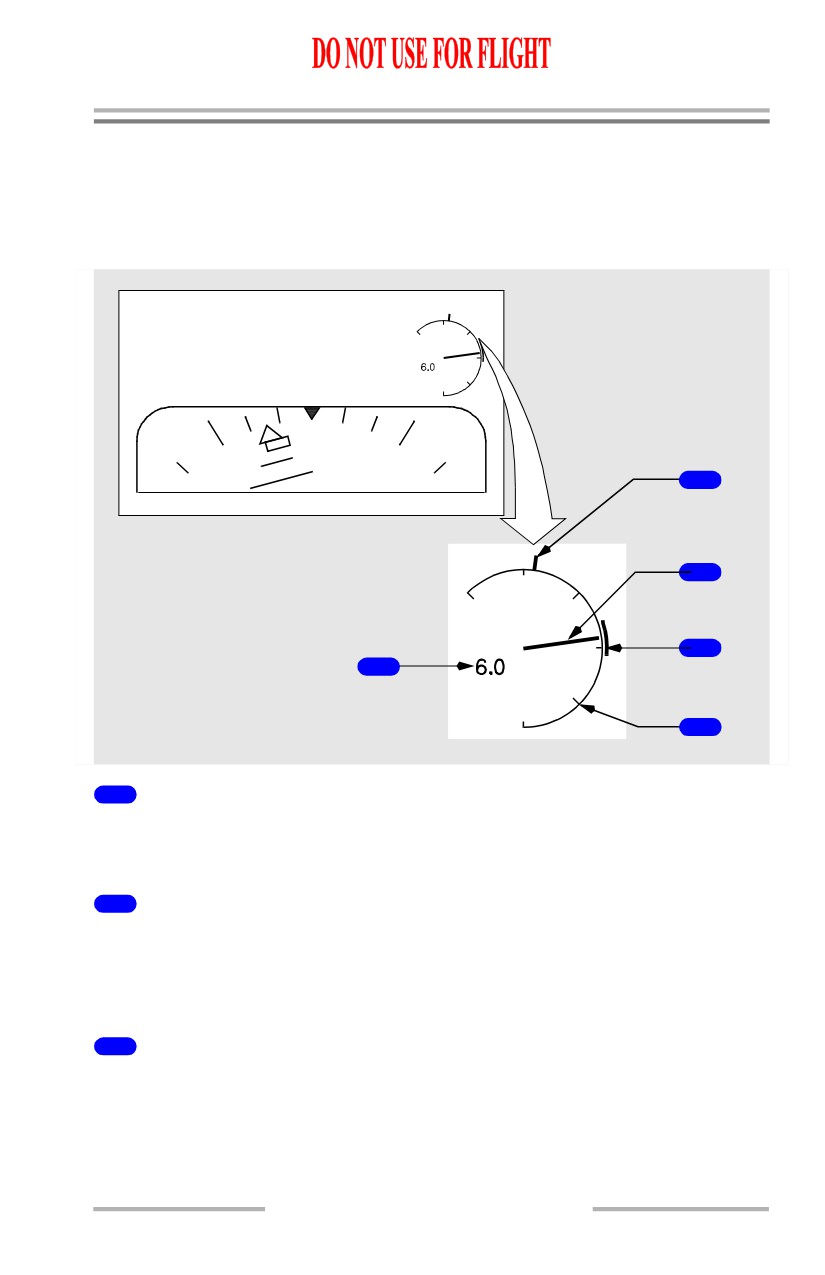
The angle of attack indications display ADIRU aircraft body angle of attack.
2
3
4
1
5
1
Digital AOA Readout (white)
Indicates digital AOA value to the nearest 0.2 degrees. When on the ground and
ground speed less than 80 knots, the readout is fixed at 0.0 degrees.
2
Stick Shaker Indicator (red)
Indicates point at which stick shaker activation occurs for existing flight
conditions.
Blank if AOA signal is invalid.
3
Analog Needle (white)
Indicates analog AOA value.
• needle travel is limited to a range of -6 degrees and +21 degrees
• fixed at 0.0 degrees when on the ground and ground speed is less than 80
knots.
10.11.11
Flight Instruments, Displays -
PFD/ND - Displays
Boeing 737 Operations Manual
4
Approach Reference Band (green)
Indicates appropriate range of approach AOA for a Vref(xx) + 5 approach.
• displayed when in normal or single engine landing flaps (15, 30, 40)
• moves with flap position
• inhibited on takeoff and initial climb.
5
Zero Degree Reference Line (white)
Indicates zero degrees angle of attack. Reference lines are displayed every 5
degrees from -5 degrees to +20 degrees.
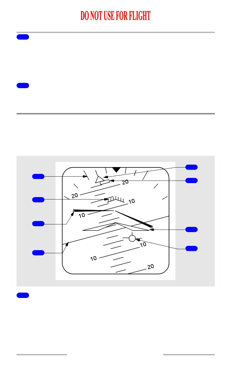
PFD - Attitude Indications
Attitude Indications - General
The attitude indication displays ADIRS attitude information.
[Option - Integrated cue command bar]
5
1
6
2
3
7
8
4
1
Bank Scale (white)
Provides fixed reference for the bank pointer; scale marks are at 0, 10, 20, 30, 45,
and 60 degrees.
10.11.12
Flight Instruments, Displays -
PFD/ND - Displays
Boeing 737 Operations Manual
2
Pitch Limit Indication (amber)
Indicates pitch limit (stick shaker activation for existing flight conditions).
• displayed when the flaps are not up.
[Option - PLI pop-up]
• displayed at slow speeds with the flaps up.
3
Flight Director Bar (magenta)
Indicates flight director steering commands. (Refer to Chapter 4, Automatic
Flight.)
4
Horizon Line and Pitch Scale (white)
Indicates the horizon relative to the airplane symbol; pitch scale is in 2.5 degree
increments.
5
Bank Pointer
Indicates bank angle; fills and turns amber if bank angle is 35 degrees or more.
6
Slip/Skid Indication
Displaces beneath the bank pointer to indicate slip or skid:
• fills white at full scale deflection
• turns amber if bank angle is 35 degrees or more; fills amber if the
slip/skid indication is also at full scale deflection.
7
Airplane Symbol
Indicates airplane attitude relative to the horizon.
8
Flight Path Vector (FPV) Indication (white)
Displays flight path angle and drift when selected on the EFIS control panel:
• flight path angle is displayed relative to the horizon line
• drift angle is displayed relative to display center.
10.11.13
Flight Instruments, Displays -
PFD/ND - Displays
Boeing 737 Operations Manual
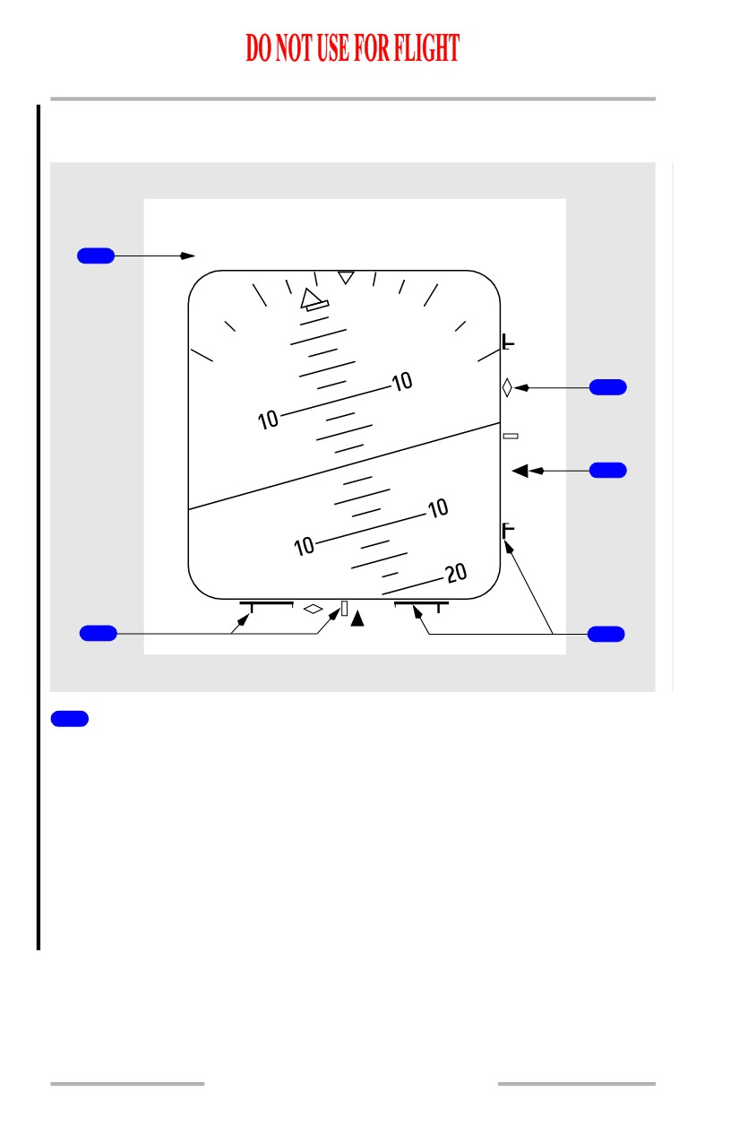
PFD LNAV/VNAV Deviation Indications
[Option - LNAV/VNAV deviation scale and pointer]
IBFI/130o
DME 3.4
1
LNAV/VNAV
5
4
2
3
1
Scale ID Annunciation (white)
• displayed in response to engaged pitch and role FMA’s.
• displayed above the left corner of ADI.
• indicates the source of displayed deviation for each scale.
• Possible annunciation combinations include:
• LOC/VNAV - (Localizer with VNAV Deviation)
• LNAV/G/S - (LNAV Deviation with Glideslope)
• LNAV/VNAV - (LNAV and VNAV Deviations)
• FAC/VNAV - (Final Approach Course and VNAV)
• LNAV/G/P - (LNAV and Glide Path)
10.11.14
Flight Instruments, Displays -
PFD/ND - Displays
Boeing 737 Operations Manual
2
LNAV/VNAV Deviation Scale
• LNAV deviation scale represents current FMC lateral RNP.
• VNAV deviation scale represents default RNP values.
• displayed if an approach mode is not engaged and either LNAV or any
VNAV mode is engaged.
3
Actual Navigation Performance (ANP) Bars
• lateral/vertical indication of available flight technical error remaining
based on total system error.
• lateral ANP bars can be displayed in all phases of flight.
• vertical ANP bars can be displayed only after reaching top-of-descent.
• originate from outer scale and expand inward as a function of increasing
ANP relative to RNP.
• will just touch at center of scale when ANP equals RNP.
• turn from white to amber if current lateral deviation is within the ANP bar
limits for 10 continuous seconds.
4
LNAV/VNAV Pointer
• a filled magenta symbol when it is not parked at deflection limit.
• an unfilled pointer outline when at deflection limit
• indicates lateral/vertical paths relative to the airplane
5
Anticipation Cues
• displayed if valid approach course deviation information is being received
while corresponding LNAV/VNAV deviation scale and pointer are
displayed.
• an unfilled white diamond symbol.
• if engaged lateral mode subsequently transitions to LOC, LNAV deviation
indications will be removed, and normal ILS localizer indications will be
displayed.
• if engaged vertical mode subsequently transitions to G/S, VNAV
deviation indications will be removed, and normal ILS G/S indications
will be displayed.
10.11.15