Boeing 737 - 600/700/800/900. Operations Manual (1997 year) - page 42
Flight Instruments, Displays -
EFIS/Map - Controls and
Indicators
Boeing 737 Operations Manual
[Option] - CDS Software Upgrade - Block point 2002
When flaps are not up, the start of the arc indicates flap extension placard speed
for the next normal flap setting. The arc is removed when the flaps reach the
landing flap selected on the APPROACH REF page or when the flaps reach flaps
40.
3
Airspeed Pointer (white)
Indicates current calibrated airspeed in knots.
4
Airspeed Cursor (magenta)
Displays target airspeed:
• indicates the airspeed manually selected in the IAS/MACH window
• indicates the FMC computed airspeed when the IAS/MACH window is
blank.
5
Mach Digital Counter (white)
Indicates current Mach number:
• displays when airspeed increases above 0.40 Mach
• blanks when airspeed decreases below 0.38 Mach.
6
Airspeed Digital Counter (white)
Indicates current calibrated airspeed in knots.
7
Stick Shaker Speed (red)
Red index mark indicates the speed at which stick shaker occurs.
8
Minimum Maneuver Speed (amber)
Amber index mark indicates minimum maneuver speed.
Inhibited on takeoff until first flap retraction or valid VREF entered.
10.10.8
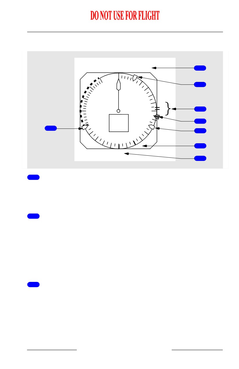
Flight Instruments, Displays -
EFIS/Map - Controls and
Indicators
Boeing 737 Operations Manual
Mach/Airspeed Indicator - Takeoff
[Option - 80 knot speed bug]
V1 125
2
6
80
8
400
100
350
120
1
3
300
R
6
140
4
250
45
1
240
160
5
4
220
180
200
1
6
UP
7
1
Bug 5 (white)
Displayed if the speed reference selector on the engine display control panel is in
the bug 5 position and a value greater than 60 knots has been selected. Not
available if the speed reference selector is in the AUTO position.
2
Speed Reference Display (green)
Displayed if the airspeed and/or weight is entered via the speed reference selector
on the engine display control panel:
• on the ground, V1, VR, and takeoff gross weight may be selected; if
VREF is selected, INVALID ENTRY is displayed
• in flight, VREF and landing gross weight may be selected; if V1 or VR is
selected, INVALID ENTRY is displayed
• removed when the speed reference selector is moved to the SET position.
3
Takeoff Reference Speeds (green)
Indicates V1 (decision speed) and VR (rotation speed) as selected on the CDU
TAKEOFF REF page (refer to Chapter 11, Flight Management, Navigation) or as
set with the speed reference selector on the engine display control panel:
• amber NO VSPD flag is displayed on the ground if V1 or VR is not
selected on the CDU or is not set with the speed reference selector
• displayed for takeoff when speed is greater than 80 knots
• removed at lift-off.
10.10.9
Flight Instruments, Displays -
EFIS/Map - Controls and
Indicators
Boeing 737 Operations Manual
[Option - V1 aural enabled]
• V1 is automatically called out by voice aural.
Note: The Look Ahead Terrain Alerting system must be incorporated for the
automatic V1 aural callout to be functional.
4
Airspeed Cursor (magenta)
Set with the speed selector on the mode control panel.
5
V2+15 (white)
Displayed for takeoff.
Removed when either of the following occurs:
• at first flap retraction
• when VREF is entered.
6
Flap Maneuvering Speed (green)
Indicates flap maneuvering speed for the displayed flap position:
• when the V2+15 bug is displayed for takeoff, the flap maneuvering speed
bug for the current flap setting is not displayed except for a flaps 1 takeoff
• flap bugs inhibited if less than VREF +4.
7
Flaps Up Airspeed (green)
Displayed after zero fuel weight is entered in the CDU and takeoff gross weight is
calculated, or after takeoff gross weight is set with the speed reference selector.
Not displayed above approximately 20,000 feet altitude.
8
80 Knots Airspeed Bug (white)
[Option - 80 knot speed bug]
Indicates 80 knots:
• displayed automatically during preflight
• removed at first flap retraction or when VREF is entered.
10.10.10
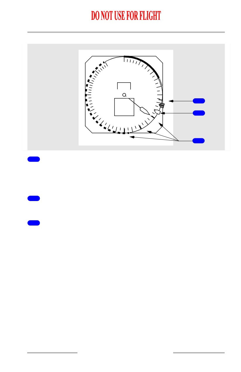
Flight Instruments, Displays -
EFIS/Map - Controls and
Indicators
Boeing 737 Operations Manual
Mach/Airspeed Indicator - Approach
60
80
400
100
350
.40
120
300
1
140
R
1
250
160
240
160
2
9
5
220
180
200
1
UP
3
1
Landing Reference Speed (green)
Indicates VREF (reference speed) as selected on the CDU APPROACH REF page
(refer to Chapter 11, Flight Management, Navigation) or as set with the speed
reference selector on the engine display control panel.
2
VREF+15
Displayed after selection of VREF.
3
Flap Maneuvering Speeds (green)
Indicate flap maneuvering speeds for the displayed flap position:
• not shown if less than or equal to VREF+4
• numbered flap maneuvering speed bugs are removed when the flap lever
is moved to flaps 30 or 40.
10.10.11
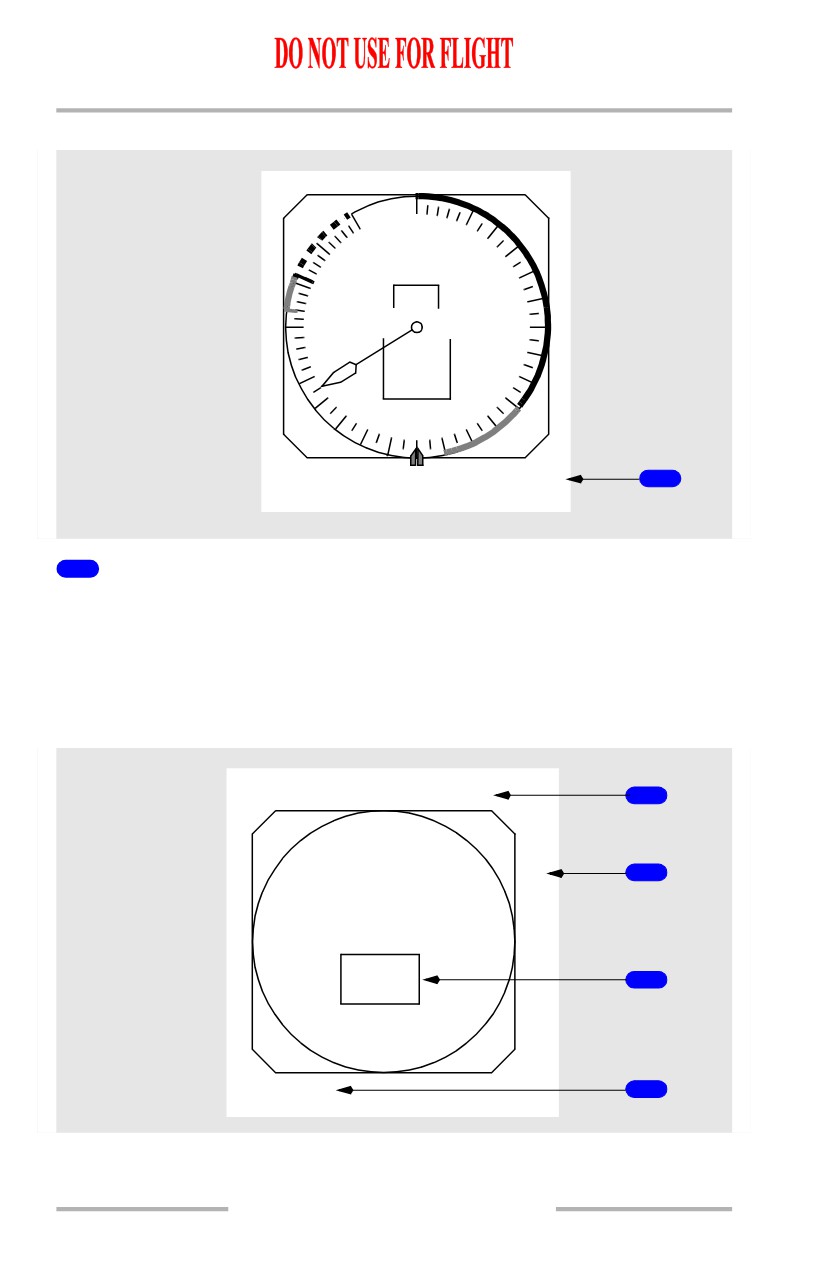
Flight Instruments, Displays -
EFIS/Map - Controls and
Indicators
Boeing 737 Operations Manual
Mach/Airspeed Indicator - IAS Disagree Alert
60
80
400
100
350
.40
120
300
6
140
250
245
240
160
4
220
180
200
IAS
UP
1
DISAGREE
1
Airspeed Disagree Alert (amber)
Indicates the Captain’s and F/O’s airspeed indications disagree by more than 5
knots for 5 continuous seconds.
Mach/Airspeed Indicator Failure Flags
The flag replaces the appropriate display to indicate source system failure or lack
of computed information.
SEL SPD
1
NO
2
V
S
P
D
SPD
3
SPD LIM
4
10.10.12
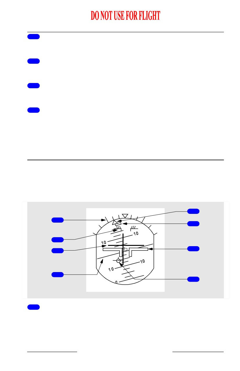
Flight Instruments, Displays -
EFIS/Map - Controls and
Indicators
Boeing 737 Operations Manual
1
Selected Speed Flag (amber)
The airspeed cursor is inoperative. The airspeed cursor is removed.
2
No VSPD Flag (amber)
V1 (decision speed) or VR (rotation speed) has not been entered or is invalid.
3
Speed Flag (amber)
The Mach/airspeed indicator is inoperative. All indicator markings are removed.
4
Speed Limit Flag (amber)
Displays related with stick shaker or maximum operating speed has failed:
• if the stick shaker warning has failed, the red stick shaker speed arc is
removed
• if the maximum operating speed has failed, the red and white maximum
operating speed arc is removed.
EFIS - Attitude Indicator
Attitude Indicator - General
The attitude indicator displays ADIRS attitude information.
[Option - Split axis command bars, flight path vector]
5
1
6
2
7
3
4
8
1
Bank Scale (white)
Provides fixed reference for the bank pointer; scale marks are at 0, 10, 20, 30, 45,
and 60 degrees.
10.10.13
Flight Instruments, Displays -
EFIS/Map - Controls and
Indicators
Boeing 737 Operations Manual
2
Pitch Limit Indicator (amber)
Indicates pitch limit (stick shaker activation for existing flight conditions).
• displayed when flaps are not up
[Option - PLI pop-up]
• displayed at slow speed with flaps up
3
Flight Director (magenta)
Indicates flight director steering commands. (Refer to Chapter 4, Automatic
Flight.)
4
Horizon Line and Pitch Scale (white)
Indicates the horizon relative to the airplane symbol; pitch scale is in 2.5 degree
increments.
5
Bank Pointer
Indicates bank angle; fills and turns amber if bank angle is 35 degrees or more.
6
Slip/Skid Indication
Displaces beneath the bank pointer to indicate slip or skid:
• fills white at full scale deflection
• turns amber if bank angle is 35 degrees or more; fills amber if the
slip/skid indicator is also at full scale deflection.
7
Airplane Symbol
Indicates airplane attitude relative to the horizon.
8
Flight Path Vector (FPV) Indication (white)
[Option - Flight path vector]
Displays flight path angle and drift when selected on the EFIS control panel:
• flight path angle is displayed relative to the horizon line
• drift angle is displayed relative to display center.
10.10.14
Flight Instruments, Displays -
EFIS/Map - Controls and
Indicators
Boeing 737 Operations Manual
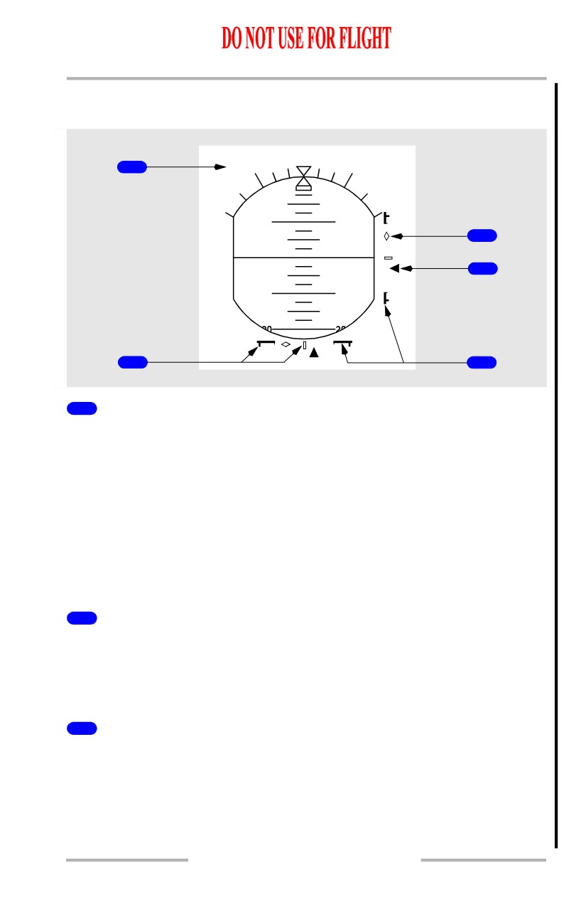
Attitude Indicator - LNAV/VNAV Deviation Indicators
[Option - LNAV/VNAV deviation scale and pointer]
1
LNAV/VNAV
10
10
5
4
10
10
2
3
1
Scale ID Annunciation (white)
• displayed in response to engaged pitch and role FMA’s.
• displayed above the left corner of ADI.
• indicates source of displayed deviation for each scale.
• Possible annunciation combinations include:
• LOC/VNAV - (Localizer with VNAV Deviation)
• LNAV/G/S - (LNAV Deviation with Glideslope)
• LNAV/VNAV - (LNAV and VNAV Deviations)
• FAC/VNAV - (Final Approach Course and VNAV)
• LNAV/G/P - (LNAV and Glide Path)
2
LNAV/VNAV Deviation Scale
• LNAV deviation scale represents current FMC lateral RNP.
• VNAV deviation scale represents default RNP values.
• displayed if an approach mode is not engaged and either LNAV or any
VNAV mode is engaged.
3
Actual Navigation Performance (ANP) Bars
• lateral/vertical indication of available flight technical error remaining
based on total system error.
• lateral ANP bars can be displayed in all phases of flight.
• vertical ANP bars can be displayed only after reaching top-of-descent.
• originate from outer scale and expand inward as a function of increasing
ANP relative to RNP.
10.10.15
Flight Instruments, Displays -
EFIS/Map - Controls and
Indicators
Boeing 737 Operations Manual
• will just touch at center of scale when ANP equals RNP.
• turn from white to amber if current lateral deviation is within ANP bar
limits for 10 continuous seconds.
4
LNAV/VNAV Pointer
• a filled magenta symbol when it is not parked at deflection limit.
• an unfilled pointer outline when at deflection limit
• indicates lateral/vertical paths relative to the airplane
5
Anticipation Cues
• displayed if valid approach course deviation information is being received
while corresponding LNAV/VNAV deviation scale and pointer are
displayed.
• an unfilled white diamond symbol.
• if engaged lateral mode subsequently transitions to LOC, LNAV deviation
indications will be removed, and normal ILS localizer indications will be
displayed.
• if engaged vertical mode subsequently transitions to G/S, VNAV
deviation indications will be removed, and normal ILS G/S indications
will be displayed.
10.10.16
Flight Instruments, Displays -
EFIS/Map - Controls and
Indicators
Boeing 737 Operations Manual
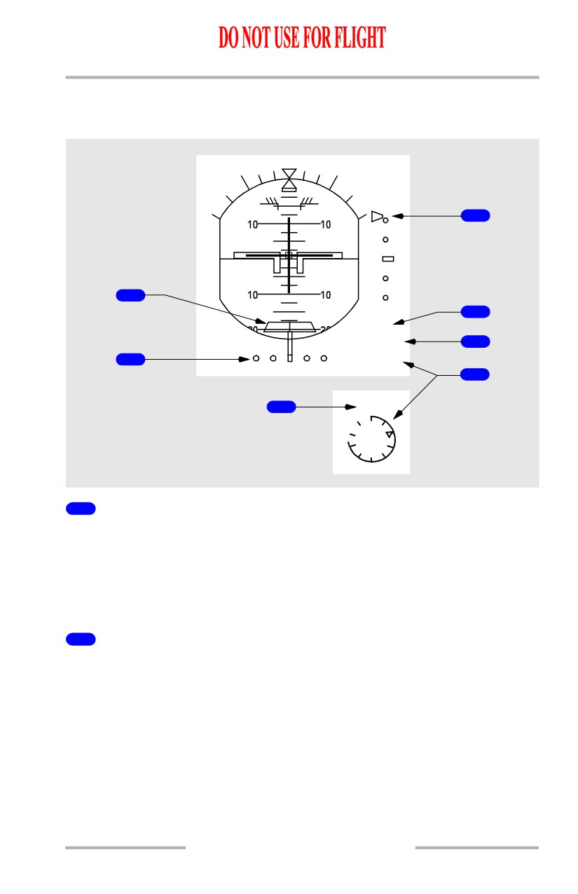
Attitude Indicator - Instrument Landing System Indications
[Option - Split axis command bars, round dial, radio altitude below, rising runway,
radio altitude height alert]
3
1
6
ALT
RADIO 200
4
2
1250
5
6
ALT
750
1
Rising Runway (green)
[Option - Rising runway]
• displayed when localizer pointer is in view and radio altitude is less than
2500 feet
• rises towards airplane symbol when radio altitude is below 200 feet
• is not displayed when the localizer signal is unusable.
2
Localizer Pointer and Deviation Scale
The pointer:
• indicates localizer position relative to the airplane
• in view when the localizer signal is received.
The scale:
• indicates deviation
• expands when the localizer is engaged and deviation is slightly more than
one-half dot
[Option - Localizer/Glideslope fail flags displayed]
• in view when the localizer signal is received.
10.10.17
Flight Instruments, Displays -
EFIS/Map - Controls and
Indicators
Boeing 737 Operations Manual
At low radio altitudes, with autopilot engaged, the scale turns amber and the
pointer flashes to indicate excessive localizer deviation.
Each pilot’s deviation alerting system self-tests upon becoming armed at 1500 feet
radio altitude. This self-test generates a two second LOC deviation alerting
display on each attitude indicator.
3
Glide Slope Pointer and Deviation Scale
The pointer:
• indicates glide slope position
• in view when the glide slope signal is received
• the pointer is not displayed when the track and the front course on the
mode control panel differ by more than 90 degrees (backcourse).
The scale:
• indicates deviation
[Option - Localizer/Glideslope fail flags displayed]
• in view when the localizer signal is received.
At low radio altitudes, with autopilot engaged, the scale turns amber and the
pointer flashes to indicate excessive glide slope deviation.
Each pilot’s deviation alerting system self-tests upon becoming armed at 1500 feet
radio altitude. This self-test generates a two second G/S deviation alerting display
on each attitude indicator.
4
Selected Radio Altitude Approach Minimums (green)
• displays selected minimums as set on the EFIS control panel
• blank when an altitude less than 0 feet is selected
•
“RADIO” legend and readout turn amber and flash for 3 seconds when
descending through the selected minimum altitude; the legend and
readout become steady amber after 3 seconds
• changes back to green:
• when passing the selected minimum altitude plus
75 feet during
go-around
• at touchdown
• after pressing the RST switch on the EFIS control panel.
5
Radio Altitude (display -white, selected radio altitude pointer-green)
[Option - Round dial]
• displayed below 2500 feet AGL
• blanked above 2500 feet AGL
• digital display from 2500 to 1000 feet AGL
• round dial display below 1000 feet AGL:
10.10.18
Flight Instruments, Displays -
EFIS/Map - Controls and
Indicators
Boeing 737 Operations Manual
• pointer replaces digital display of selected radio minimum altitude
• the circumference of the dial is added to, or taken away from, to depict
the airplane’s radio altitude
• dial and readout turn amber and dial flashes for 3 seconds when
descending through the selected minimum altitude; the dial becomes
steady amber after 3 seconds
• changes back to white:
• when passing through the selected minimum altitude plus 75 feet during
go-around
• at touchdown
• after pressing the RST switch on the EFIS control panel.
6
Radio Altitude Height Alert (white)
[Option - 2500 ft height alert]
Displayed when radio altitude is less than or equal to 2500 feet. Blanked when
descent continues below 500 feet AGL, or after pressing the RST switch on the
EFIS control panel.
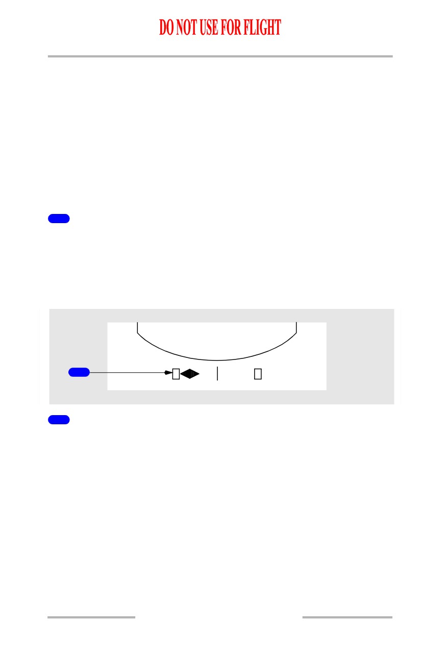
Expanded Localizer Indications
1
1
Expanded Localizer Scale
[Option - Autopilot or flight director activated]
Displayed when the autopilot or flight director is in LOC mode, deviation is
slightly more than one half dot and track is within 5 degrees of the MCP selected
course.
Reverts to standard scale when out of LOC mode, and groundspeed is less than 30
knots or radio altitude is greater than 200 feet.
A rectangle equals 1/2 dot deviation.
10.10.19
Flight Instruments, Displays -
EFIS/Map - Controls and
Indicators
Boeing 737 Operations Manual
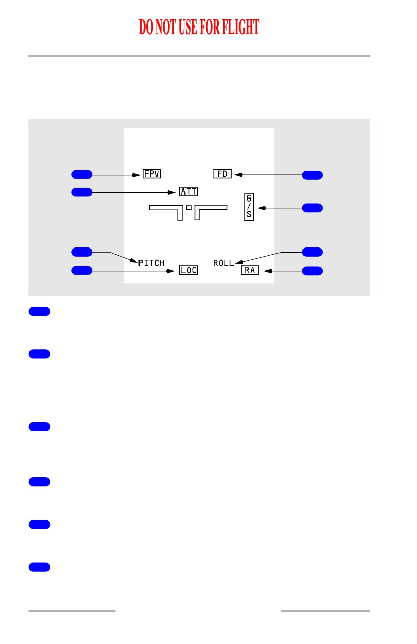
Attitude Indicator Failure Flags
Flags replace the attitude displays to indicate source system failure or lack of
computed information.
[Option - Split axis command bars, radio altitude below, flight path vector]
8
5
1
6
2
7
3
4
1
Attitude Flag (amber)
The attitude display has failed.
2
Pitch Flag (amber)
The Captain and First Officer pitch angle displays differ by more than 5 degrees.
[Option - Attitude comparator flashing]
The flag flashes for 10 seconds then remains steady.
3
Localizer Flag (amber)
An ILS frequency is tuned and the ILS localizer deviation display on the attitude
indicator has failed.
4
Radio Altitude Flag (amber)
The radio altitude display has failed.
5
Flight Director Flag (amber)
The flight director has failed.
6
Glide Slope Flag (amber)
An ILS frequency is tuned and the ILS glide slope deviation display on the attitude
indicator has failed.
10.10.20
Flight Instruments, Displays -
EFIS/Map - Controls and
Indicators
Boeing 737 Operations Manual
7
Roll Flag (amber)
The Captain and First Officer roll displays differ by more than 5 degrees.
[Option - Attitude comparator flashing]
The flag flashes for 10 seconds then remains steady.
8
Flight Path Vector Flag (amber)
[Option - Flight path vector]
FPV is selected on the EFIS control panel, but has failed. De-selection of FPV
removes the flag.
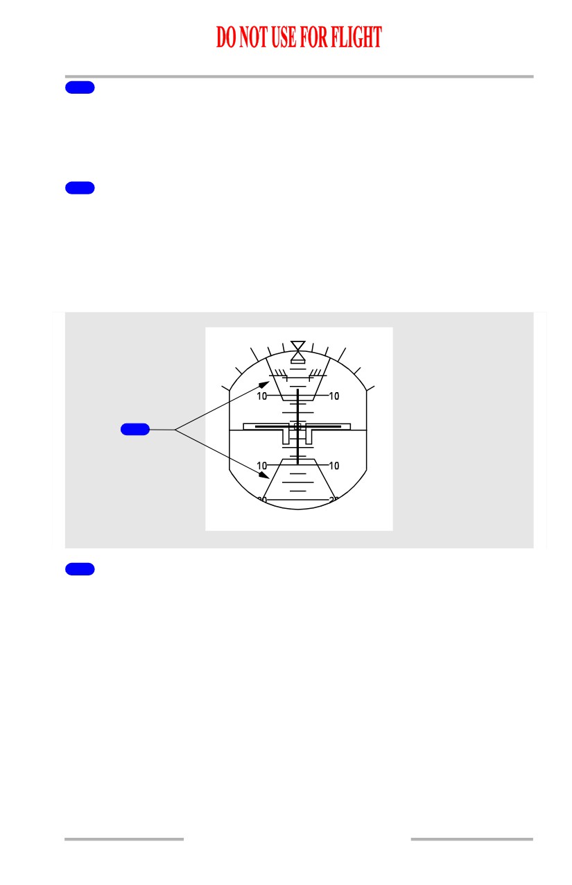
Traffic Alert and Collision Avoidance Indications
[Option - Split axis command bars]
1
1
Traffic Alert and Collision Avoidance System Pitch Command (red)
The area(s) inside the red lines indicate(s) the pitch region(s) to avoid in order to
resolve the traffic conflict. The airplane symbol must be outside the TCAS pitch
command area(s) to ensure traffic avoidance. Refer to Chapter 15, Warning
Systems.
10.10.21
Flight Instruments, Displays -
EFIS/Map - Controls and
Indicators
Boeing 737 Operations Manual
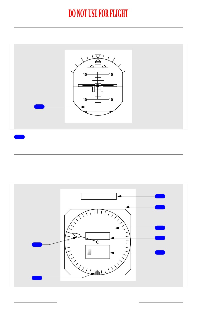
GPWS Annunciations
[Option - Split axis command bars]
1
PULL UP
1
GPWS Annunciations (red)
Refer to Chapter 15, Warning Systems.
EFIS - Altimeter
Altimeter - General
The altimeter displays ADIRS altitude and other altitude related information.
ALT ALERT
3
457
M
4
0
9
1
29.92
IN.
5
8
2
243 M
6
1
7
3
0
800
7
6
80 4
5
2
10.10.22
Flight Instruments, Displays -
EFIS/Map - Controls and
Indicators
Boeing 737 Operations Manual
1
Altitude Pointer
Makes one revolution each one thousand feet.
2
Reference Altitude Marker (green)
Indicates the barometric minimums as set by the minimums selector on the EFIS
control panel.
The minimums reference selector must be in the BARO position to adjust the
reference altitude marker.
3
Altitude Alert Annunciation (amber)
• appears steady for altitude acquisition
• flashes during altitude deviation
• refer to Chapter 15, Warning Systems.
4
Metric Selected Altitude Readout (readout-magenta, caption-cyan)
Displays MCP altitude in meters when MTRS is selected on the EFIS control
panel. Not available in compact mode.
5
Barometric Setting (green)
Indicates the barometric setting in either inches of mercury (IN) or hectopascals
(HPA) as selected on the EFIS control panel.
6
Metric Digital Readout (readout-white, caption-cyan)
Displays current altitude in meters when MTRS is selected on the EFIS control
panel. Not available in compact mode.
7
Digital Readout (white)
Displays current altitude in increments of thousands, hundreds and twenty feet:
• for positive values of altitude below 10,000 feet, a green crosshatch
symbol is displayed
• a negative sign appears when altitude below zero feet is displayed.
10.10.23
Flight Instruments, Displays -
EFIS/Map - Controls and
Indicators
Boeing 737 Operations Manual
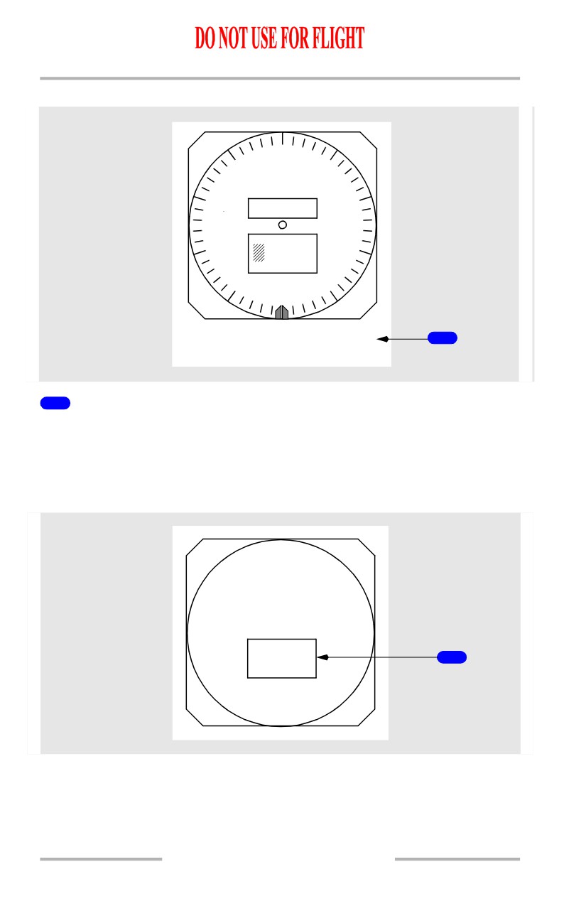
Altimeter - Altitude Disagree Alert
0
9
1
29.92
IN.
2
243 M
7
3
0
800
6
4
5
ALT
1
DISAGREE
1
Altitude Disagree Alert (amber)
Indicates the Captain’s and F/O’s altitude indications disagree by more than 200
feet for more than 5 continuous seconds.
Altimeter Failure Flag
The failure flag replaces the altitude displays to indicate system failure.
29.92
IN.
ALT
1
10.10.24
Flight Instruments, Displays -
EFIS/Map - Controls and
Indicators
Boeing 737 Operations Manual
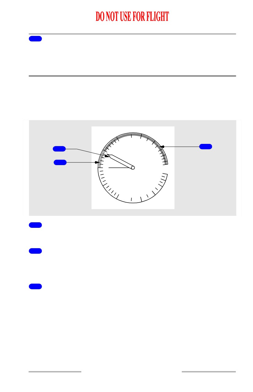
1
Altitude Failure Flag (amber)
The barometric altitude or barometric correction has failed:
• all altimeter symbols are removed except the ALT ALERT annunciation
and the barometric setting.
EFIS - Vertical Speed Indicator
Vertical Speed Indicator - General
The vertical speed indicator displays ADIRS instantaneous vertical speed.
[Option - TCAS advisory]
2
1
3
1
.5
4
2
0
6
.5
4
1
2
1
Vertical Speed Pointer (white)
Depicts rate of climb or descent from 0 to 6000 feet per minute.
2
TCAS Corrective Advisory (green)
[Option - TCAS advisory]
Indicates range of recommended vertical speed.
3
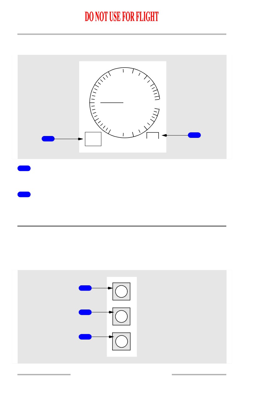
TCAS Preventative Advisory (red)
[Option - TCAS advisory]
Indicates range of vertical speed to be avoided.
10.10.25
Flight Instruments, Displays -
EFIS/Map - Controls and
Indicators
Boeing 737 Operations Manual
Vertical Speed Indicator Failure Flag
[Option - VSI TCAS advisory]
2
1
.5
4
0
6
.5
4
1
2
TCAS
VSI
1
2
FAIL
1
VSI Failure Flag (amber)
Vertical speed has failed. The pointer is also removed.
2
TCAS Failure Flag (amber)
[Option - VSI TCAS advisory]
TCAS advisory function has failed. Compact format only.
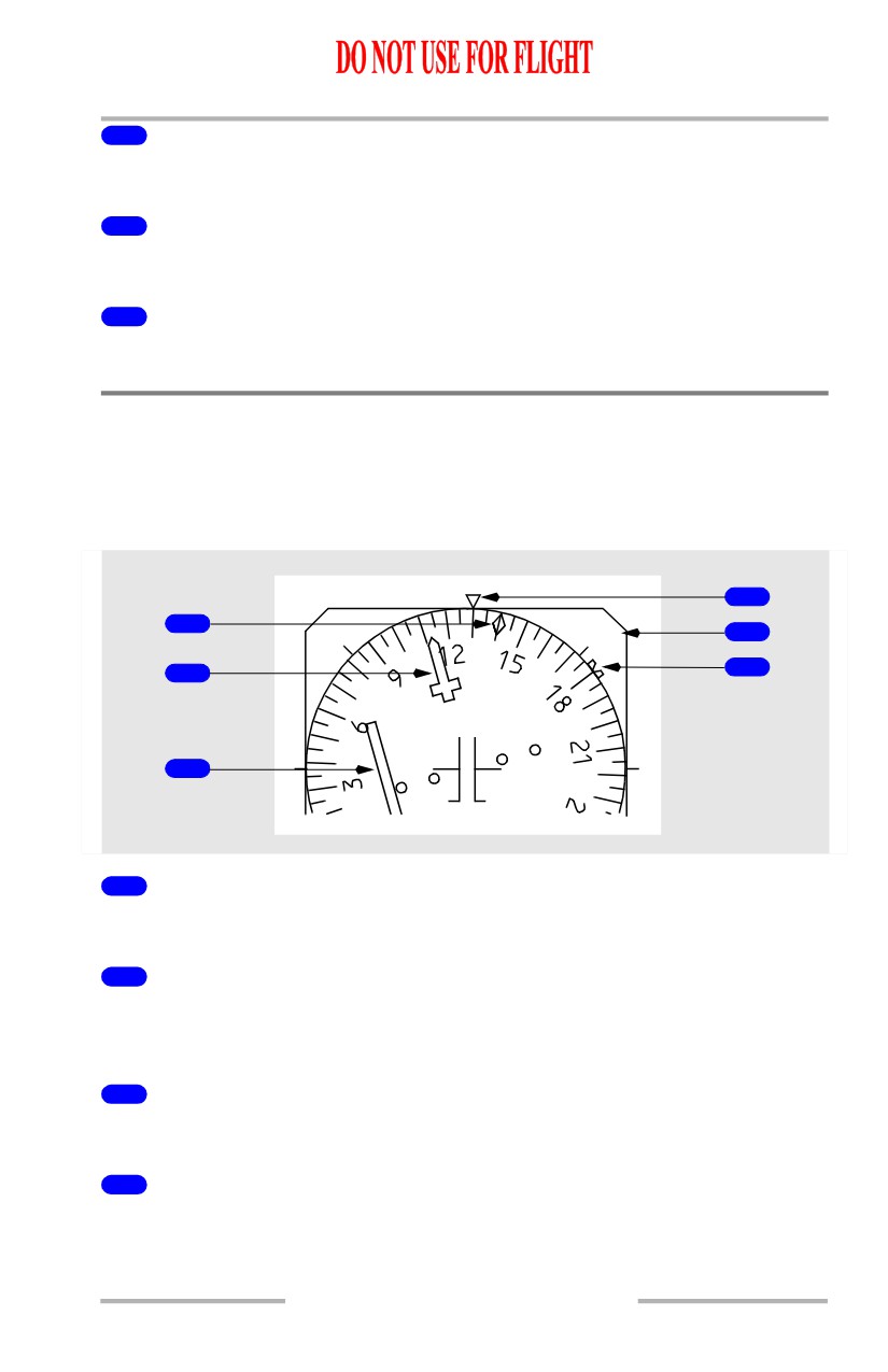
EFIS - Marker Beacon Indications
Marker Beacons Indications
The marker beacon indication flashes when over one of the marker beacon
transmitters.
1
OM
2
MM
3
IM
10.10.26
Flight Instruments, Displays -
EFIS/Map - Controls and
Indicators
Boeing 737 Operations Manual
1
Outer Marker (cyan)
Flashes when over an outer marker beacon.
2
Middle Marker (amber)
Flashes when over a middle marker beacon.
3
Inner Marker (white)
Flashes when over an airway or inner marker beacon.
Navigation Displays -
Horizontal Situation Indicator (HSI)
Horizontal Situation Indicator - General
The HSI displays current ADIRS heading, track and other information.
4
1
ILS
5
2
6
3
1
Drift Angle Pointer (white)
Indicates current drift angle or track.
2
Selected Course Pointer (white)
Indicates the course set on the mode control panel. Set by the related mode control
panel course selector.
3
Course Deviation Indicator (magenta)
Indicates deviation from the selected localizer or VOR course.
4
Heading Pointer (white)
Indicates current heading.
10.10.27