Boeing 737 - 600/700/800/900. Operations Manual (1997 year) - page 40
Flight Controls -
System Description
Boeing 737 Operations Manual
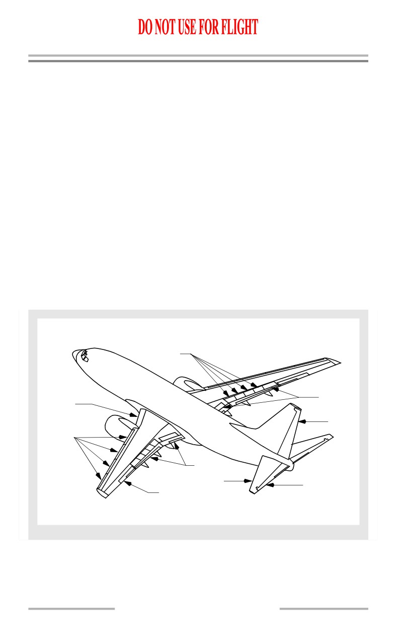
Flight Control Surfaces
Pitch control is provided by:
• two elevators
• a movable horizontal stabilizer.
Roll control is provided by:
• two ailerons
• eight flight spoilers.
Yaw control is provided by a single rudder. During takeoff, the rudder becomes
aerodynamically effective between 40 and 60 knots.
TE flaps and LE flaps and slats provide high lift for takeoff, approach and landing.
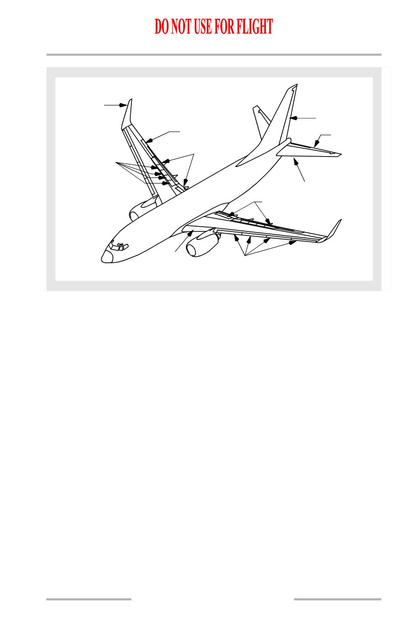
[Option: 737-800 with Blended Winglets]
Blended winglets provide enhanced performance, extended range and increased
fuel efficiency.
In the air symmetric flight spoilers are used as speed brakes. On the ground
symmetric flight and ground spoilers destroy lift and increase braking efficiency.
Flight Control Surfaces Location
FLIGHT
SPOILERS
GROUND
LE FLAPS
SPOILERS
RUDDER
LE SLATS
TE FLAPS
STABILIZER
ELEVATORS
AILERONS
9.20.2
Flight Controls -
System Description
Boeing 737 Operations Manual
[Option: 737-800 with Blended Winglets]
BLENDED
WINGLETS
RUDDER
AILERONS
ELEVATORS
TE FLAPS
FLIGHT
SPOILERS
STABILIZER
GROUND
SPOILERS
LE FLAPS
LE SLATS
October 15, 2001
9.20.3
Flight Controls -
System Description
Boeing 737 Operations Manual
Roll Control
The roll control surfaces consist of hydraulically powered ailerons and flight
spoilers, which are controlled by rotating either control wheel.
Ailerons
The ailerons provide roll control around the airplane’s longitudinal axis. The
ailerons are positioned by the pilots' control wheels. The A and B FLT CONTROL
switches control hydraulic shutoff valves. These valves can be used to isolate each
aileron, as well as the elevators and rudder, from related hydraulic system
pressure.
The Captain’s control wheel is connected by cables to the aileron power control
units (PCUs) through the aileron feel and centering unit. The First Officer’s
control wheel is connected by cables to the spoiler PCUs through the spoiler
mixer. The two control wheels are connected by a cable drive system which allows
actuation of both ailerons and spoilers by either control wheel. With total
hydraulic power failure the ailerons can be mechanically positioned by rotating
the pilots' control wheels. Control forces are higher due to friction and
aerodynamic loads.
Aileron Transfer Mechanism
If the ailerons or spoilers are jammed, force applied to the Captain’s and the First
Officer’s control wheels will identify which system, ailerons or spoilers, is usable
and which control wheel, Captain’s or First Officer’s, can provide roll control. If
the aileron control system is jammed, force applied to the First Officer’s control
wheel provides roll control from the spoilers. The ailerons and the Captain’s
control wheel are inoperative. If the spoiler system is jammed, force applied to the
Captain’s control wheel provides roll control from the ailerons. The spoilers and
the First Officer’s control wheel are inoperative.
Aileron Trim
Dual AILERON trim switches, located on the aft electronic panel, must be pushed
simultaneously to command trim changes. The trim electrically repositions the
aileron feel and centering unit, which causes the control wheel to rotate and
redefines the aileron neutral position. The amount of aileron trim is indicated on
a scale on the top of each control column.
If aileron trim is used with the autopilot engaged, the trim is not reflected in the
control wheel position. The autopilot overpowers the trim and holds the control
wheel where it is required for heading/track control. Any aileron trim applied
when the autopilot is engaged can result in an out of trim condition and an abrupt
rolling movement when the autopilot is disconnected.
9.20.4
Flight Controls -
System Description
Boeing 737 Operations Manual
Flight Spoilers
Four flight spoilers are located on the upper surface of each wing. Each hydraulic
system, A and B, is dedicated to a different set of spoiler pairs to provide isolation
and maintain symmetric operation in the event of hydraulic system failure.
Hydraulic pressure shutoff valves are controlled by the two flight SPOILER
switches.
Flight spoiler panels are used as speed brakes to increase drag and reduce lift, both
in flight and on the ground. The flight spoilers also supplement roll control in
response to control wheel commands. A spoiler mixer, connected to the aileron
cable-drive, controls the hydraulic power control units on each spoiler panel to
provide spoiler movement proportional to aileron movement.
The flight spoilers rise on the wing with up aileron and remain faired on the wing
with down aileron. When the control wheel is displaced more than approximately
10°, spoiler deflection is initiated.
9.20.5
Flight Controls -
System Description
Boeing 737 Operations Manual
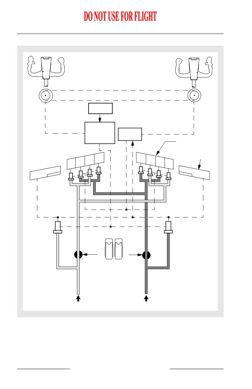
Roll Control Schematic
AILERON TRANSFER
MECHANISM
AILERON
TRIM
AILERON
FEEL AND
SPOILER
CENTERING
MIXER
UNIT
FLIGHT
SPOILERS
AILERON
5
8
4
9
3
10
2
11
SPOILER
A
B
OFF
OFF
ON
ON
A
B
9.20.6
Flight Controls -
System Description
Boeing 737 Operations Manual
Pitch Control
The pitch control surfaces consist of hydraulically powered elevators and an
electrically powered stabilizer. The elevators are controlled by forward or aft
movement of the control column. The stabilizer is controlled by autopilot trim or
manual trim.
Elevators
The elevators provide pitch control around the airplane’s lateral axis. The
elevators are positioned by the pilots’ control columns. The A and B FLT
CONTROL switches control hydraulic shutoff valves for the elevators.
Cables connect the pilots’ control columns to elevator power control units (PCUs)
which are powered by hydraulic system A and B. The elevators are interconnected
by a torque tube. With loss of hydraulic system A and B the elevators can be
mechanically positioned by forward or aft movement of the pilots’ control
columns. Control forces are higher due to friction and aerodynamic loads.
Elevator Control Column Override Mechanism
In the event of a control column jam, an override mechanism allows the control
columns to be physically separated. Applying force against the jam will breakout
either the Captain’s or First Officer’s control column. Whichever column moves
freely after the breakout can provide adequate elevator control.
Although total available elevator travel is significantly reduced, there is sufficient
elevator travel available for landing flare. Column forces are higher and exceed
those experienced during manual reversion. If the jam exists during the landing
phase, higher forces are required to generate sufficient elevator control to flare for
landing. Stabilizer trim is available to counteract the sustained control column
force.
Elevator Feel System
The elevator feel computer provides simulated aerodynamic forces using airspeed
(from the elevator pitot system) and stabilizer position. Feel is transmitted to the
control columns by the elevator feel and centering unit. To operate the feel system
the elevator feel computer uses either hydraulic system A or B pressure,
whichever is higher. When either hydraulic system or elevator feel pitot system
fails, excessive differential hydraulic pressure is sensed in the elevator feel
computer and the FEEL DIFF PRESS light illuminates.
9.20.7
Flight Controls -
System Description
Boeing 737 Operations Manual
Mach Trim System
A Mach trim system provides speed stability at the higher Mach numbers. Mach
trim is automatically accomplished above Mach .615 by adjusting the elevators
with respect to the stabilizer as speed increases. The flight control computers use
Mach information from the ADIRU to compute a Mach trim actuator position.
The Mach trim actuator repositions the elevator feel and centering unit which
adjusts the control column neutral position.
Stabilizer
The horizontal stabilizer is positioned by a single electric trim motor controlled
through either the stab trim switches on the control wheel or autopilot trim. The
stabilizer may also be positioned by manually rotating the stabilizer trim wheel.
Stabilizer Trim
Stabilizer trim switches on each control wheel actuate the electric trim motor
through the main electric stabilizer trim circuit when the airplane is flown
manually. With the autopilot engaged, stabilizer trim is accomplished through the
autopilot stabilizer trim circuit. The main electric and autopilot stabilizer trim
have two speed modes: high speed with flaps extended and low speed with flaps
retracted. If the autopilot is engaged, actuating either pair of stabilizer trim
switches automatically disengages the autopilot. The stabilizer trim wheels rotate
whenever electric stabilizer trim is actuated.
The STAB TRIM MAIN ELECT cutout switch and the STAB TRIM
AUTOPILOT cutout switch, located on the control stand, are provided to allow
the autopilot or main electric trim inputs to be disconnected from the stabilizer
trim motor.
Control column actuated stabilizer trim cutout switches stop operation of the main
electric and autopilot trim when the control column movement opposes trim
direction. When the STAB TRIM override switch is positioned to OVERRIDE,
electric trim can be used regardless of control column position.
Manual stabilizer control is accomplished through cables which allow the pilot to
position the stabilizer by rotating the stabilizer trim wheels. The stabilizer is held
in position by two independent brake systems. Manual rotation of the trim wheels
can be used to override autopilot or main electric trim. The effort required to
manually rotate the stabilizer trim wheels may be higher under certain flight
conditions. Grasping the stabilizer trim wheel will stop stabilizer motion.
Stabilizer Trim Operation with Forward or Aft CG
In the event the stabilizer is trimmed to the end of the electrical trim limits,
additional trim is available through the use of the manual trim wheels. If manual
trim is used to position the stabilizer beyond the electrical trim limits, the stabilizer
trim switches may be used to return the stabilizer to electrical trim limits.
9.20.8
Flight Controls -
System Description
Boeing 737 Operations Manual
Stabilizer Position Indication and Green Band
Stabilizer position is displayed in units on two STAB TRIM indicators located
inboard of each stabilizer trim wheel. The STAB TRIM indicators also display the
TAKEOFF green band indication.
The trim authority for each mode of trim is limited to:
• Main Electric Trim
[737-600]
• flaps retracted 4.10 to 14.5 units
[737-700]
• flaps retracted 4.30 to 14.5 units
[737-800]
• flaps retracted 3.95 to 14.5 units
[737-900]
• flaps retracted 3.90 to 14.5 units
• flaps extended 0.05 to 14.5 units
• Autopilot Trim 0.05 to 14.5 units
• Manual Trim -0.20 to 16.9 units.
The green band range of the STAB TRIM indicator shows the takeoff trim range.
An intermittent horn sounds if takeoff is attempted with the stabilizer trim outside
the takeoff trim range.
Speed Trim System
The speed trim system (STS) is a speed stability augmentation system designed to
improve flight characteristics during operations with a low gross weight, aft center
of gravity and high thrust when the autopilot is not engaged. The purpose of the
STS is to return the airplane to a trimmed speed by commanding the stabilizer in
a direction opposite the speed change. The STS monitors inputs of stabilizer
position, thrust lever position, airspeed and vertical speed and then trims the
stabilizer using the autopilot stabilizer trim. As the airplane speed increases or
decreases from the trimmed speed, the stabilizer is commanded in the direction to
return the airplane to the trimmed speed. This increases control column forces to
force the airplane to return to the trimmed speed. As the airplane returns to the
trimmed speed, the STS commanded stabilizer movement is removed.
STS operates most frequently during takeoffs, climb and go-arounds. Conditions
for speed trim operation are listed below:
• Airspeed between 100 KIAS and
• N1 above 60%
Mach 0.68
• Autopilot not engaged
•
10 seconds after takeoff
• Sensing of trim requirement
•
5 seconds following release of
trim switches
9.20.9
Flight Controls -
System Description
Boeing 737 Operations Manual
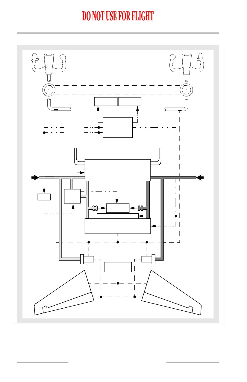
Pitch Control Schematic
ELEVATOR CONTROL COLUMN
OVERRIDE MECHANISM
MACH TRIM
SPEED TRIM
FAIL
FAIL
FLIGHT
L/ADIRU
CONTROL
R/ADIRU
COMPUTER
L PITOT
R PITOT
PROBE
PROBE
ELEVATOR
STABILIZER
FEEL
POSITION
COMPUTER
A
B
EFS
SMYD
MODULE
FEEL
DIFF PRESS
MACH TRIM ACTUATOR
ELEVATOR FEEL
& CENTERING UNIT
STABILIZER
TRIM
9.20.10
Flight Controls -
System Description
Boeing 737 Operations Manual
Stall Identification
Stall identification and control is enhanced by the yaw damper, the Elevator Feel
Shift (EFS) module and the speed trim system. These three systems work together
to help the pilot identify and prevent further movement into a stall condition.
During high AOA operations, the SMYD reduces yaw damper commanded rudder
movement.
The EFS module increases hydraulic system A pressure to the elevator feel and
centering unit during a stall. This increases forward control column force to
approximately two times normal feel pressure. The EFS module is armed
whenever an inhibit condition is not present. Inhibit conditions are: on the ground,
radio altitude less than 100 feet and autopilot engaged. However, if EFS is active
when descending through 100 feet RA, it remains active until AOA is reduced
below approximately stickshaker threshold. There are no flight deck indications
that the system is properly armed or activated.
As airspeed decreases towards stall speed, the speed trim system trims the
stabilizer nose down and enables trim above stickshaker AOA. With this trim
schedule the pilot must pull more aft column to stall the airplane. With the column
aft, the amount of column force increase with the onset of EFS module is more
pronounced.
9.20.11
Flight Controls -
System Description
Boeing 737 Operations Manual
Yaw Control
Yaw control is accomplished by a hydraulically powered rudder and a digital yaw
damper system. The rudder is controlled by displacing the rudder pedals. The yaw
damping functions are controlled through the stall management/yaw damper
(SMYD) computers.
Rudder
The rudder provides yaw control about the airplane’s vertical axis. The A and B
FLT CONTROL switches control hydraulic shutoff valves for the rudder and the
standby rudder.
[737 modified rudder - not installed]
Each set of rudder pedals is mechanically connected by cables to the input levers
of the main and standby rudder PCUs. The main rudder PCU is powered by
hydraulic system A and B. The standby rudder PCU is powered by the standby
hydraulic system. At speeds above approximately 135 kts, hydraulic system A
pressure to the rudder PCU is reduced. This function limits full rudder authority
in flight after takeoff and before landing.
[737 modified rudder- installed]
Each set of rudder pedals is mechanically connected by cables to the input levers
of the main and standby rudder PCUs. The main PCU consists of two independent
input rods, two individual control valves, and two separate actuators; one for
Hydraulic system A and one for Hydraulic system B. The standby rudder PCU is
controlled by a separate input rod and control valve and powered by the standby
hydraulic system. All three input rods have individual jam override mechanisms
that allows input commands to continue to be transferred to the remaining free
input rods if an input rod is hindered or jammed.
[737 modified rudder - installed]
At speeds above approximately 135 kts, both hydraulic system A and B pressure
are reduced within the main PCU. This function limits full rudder authority in
flight after takeoff and before landing.
[737 modified rudder - installed]
The main rudder PCU contains a Force Fight Monitor (FFM) that detects opposing
pressure (force fight) between A and B actuators. This may occur if either system
A or B input is jammed or failed. The FFM output is used to automatically turn on
the Standby Hydraulic pump pressurizing the standby PCU.
The standby rudder PCU is powered by the standby hydraulic system. The standby
hydraulic system is provided as a backup if system A and/or B pressure is lost.
With the standby PCU powered the pilot retains adequate rudder control
capability. It can be operated manually through the FLT CONTROL switches or
automatically. (Refer to Chapter 13, Hydraulics, Standby Hydraulic System)
9.20.12
Flight Controls -
System Description
Boeing 737 Operations Manual
[737 modified rudder- installed]
An amber STBY RUD ON light illuminates when the standby rudder hydraulic
system is pressurized. STBY RUD ON light illumination activates Master Caution
and Flight Control warning lights on the Systems Annunciation Panel.
Rudder Trim
The RUDDER trim control, located on the aft electronic panel, electrically
repositions the rudder feel and centering unit which adjusts the rudder neutral
position. The rudder pedals are displaced proportionately. The RUDDER TRIM
indicator displays the rudder trim position in units.
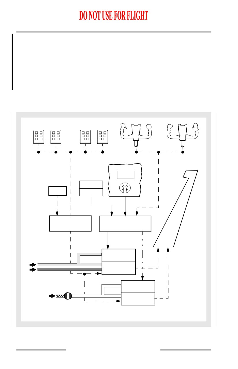
Yaw Damper
The yaw damper system consists of a main and standby yaw damper. Both yaw
dampers are controlled through Stall Management/Yaw Damper
(SMYD)
computers. The SMYD computers receive inputs from both ADIRUs, both control
wheels and the YAW DAMPER switch. SMYDs provide yaw damper inputs to the
main rudder power control unit (PCU) or standby rudder PCU, as appropriate.
Either yaw damper is capable of providing dutch roll prevention, gust damping
and turn coordination. Yaw damper operation does not result in rudder pedal
movement. Only main yaw damper inputs are shown on the yaw damper indicator.
The pilot can override either main or standby yaw damper inputs using either the
rudder pedals or trim inputs.
During normal operation the main yaw damper uses hydraulic system B and the
SMYD computers provide continuous system monitoring. If the SMYD senses a
system fault, the YAW DAMPER Switch is automatically moved to the OFF
position, the amber YAW DAMPER light illuminates, the yaw damper is
disconnected and the YAW DAMPER switch cannot be reset to ON. If hydraulic
system B pressure is lost, the YAW DAMPER switch remains in the ON position
until the B FLT CONTROL switch is positioned to OFF or STBY RUD. Then the
YAW DAMPER switch disengages, the amber YAW DAMPER light illuminates
and the YAW DAMPER switch cannot be reengaged.
During manual reversion flight (loss of hydraulic system A and B pressure), both
FLT CONTROL switches are positioned to STBY RUD. In this case, the YAW
DAMPER switch can be reset to ON and the standby hydraulic system powers the
standby yaw damper.
9.20.13
Flight Controls -
System Description
Boeing 737 Operations Manual
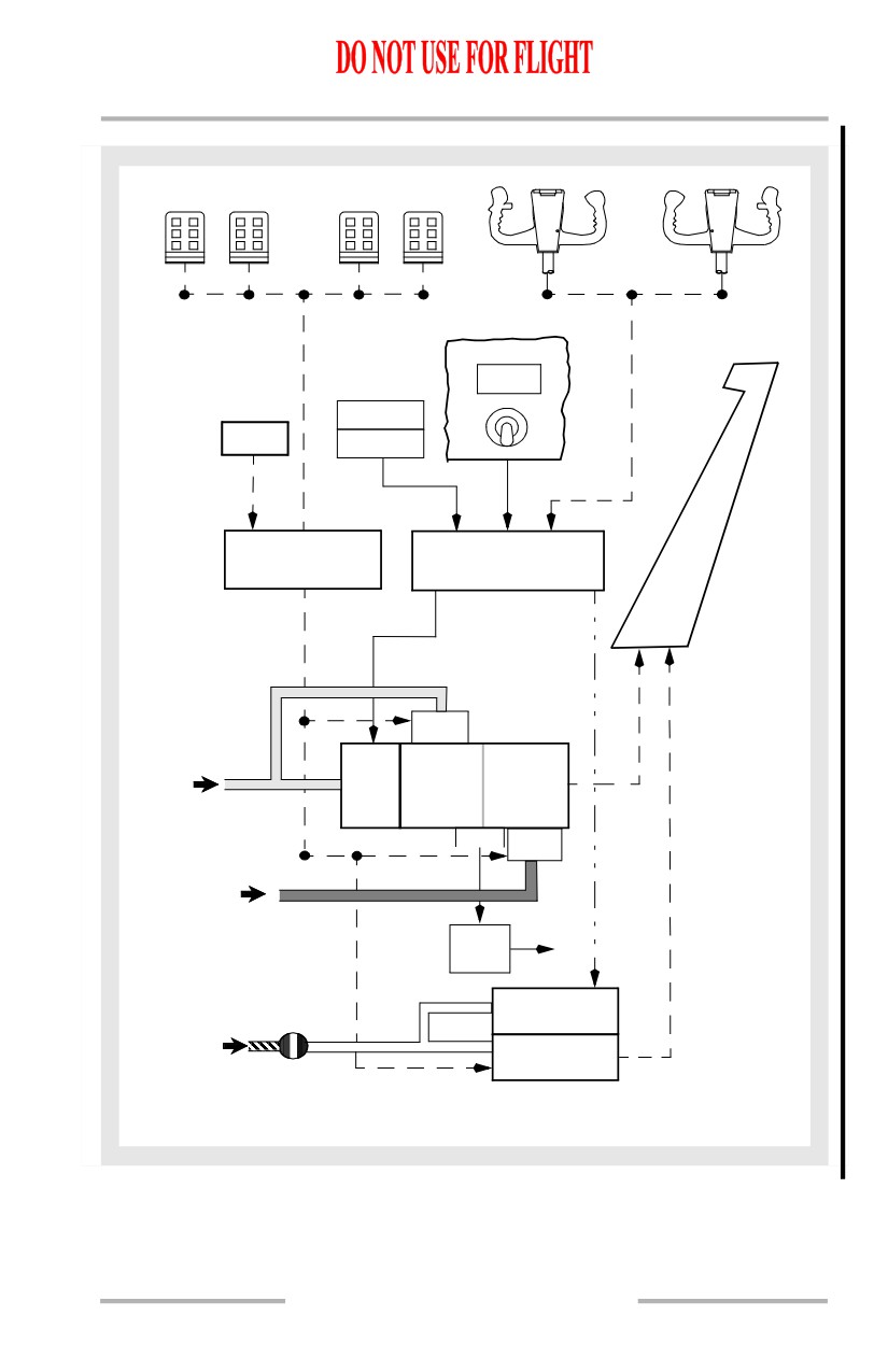
[737 modified rudder- installed]
During manual reversion flight (loss of hydraulic system A and B pressure), both
FLT CONTROL switches are positioned to STBY RUD. In this case, the YAW
DAMPER switch can be reset to ON and the standby hydraulic system powers the
standby yaw damper. During Standby Yaw Damper operation, movement of the
control wheel sends a signal to the standby rudder PCU to move the rudder. This
gives rudder assist to help turn the airplane when control of the ailerons is through
manual reversion.
Yaw Control Schematic
[737 modified rudder - not installed]
YAW DAMPER
YAW
DAMPER
L/ADIRU
OFF
RUDDER
ON
TRIM
R/ADIRU
RUDDER FEEL
STALL MANAGEMENT
AND CENTERING
YAW DAMPER
UNIT
COMPUTERS
RUDDER
MAIN
YAW DAMPER
B
MAIN
A
RUDDER PCU
STANDBY
YAW DAMPER
STANDBY
STANDBY
STANDBY
RUDDER PCU
RUDDER
SHUTOFF
VALVE
9.20.14
Flight Controls -
System Description
Boeing 737 Operations Manual
[737 modified rudder- installed]
YAW DAMPER
YAW
DAMPER
L/ADIRU
OFF
RUDDER
ON
TRIM
R/ADIRU
RUDDER FEEL
STALL MANAGEMENT
AND CENTERING
YAW DAMPER
UNIT
COMPUTERS
RUDDER
Control
Valve
MAIN
HYD B
YAW
MAIN RUDDER PCU
DAMPER
FFM
Control
Valve
HYD A
STBY Hyd
STBY
Auto-On
Hyd
Logic
Pump
STANDBY
YAW DAMPER
STANDBY
STANDBY
STANDBY
RUDDER PCU
RUDDER
SHUTOFF
VALVE
9.20.15
Flight Controls -
System Description
Boeing 737 Operations Manual
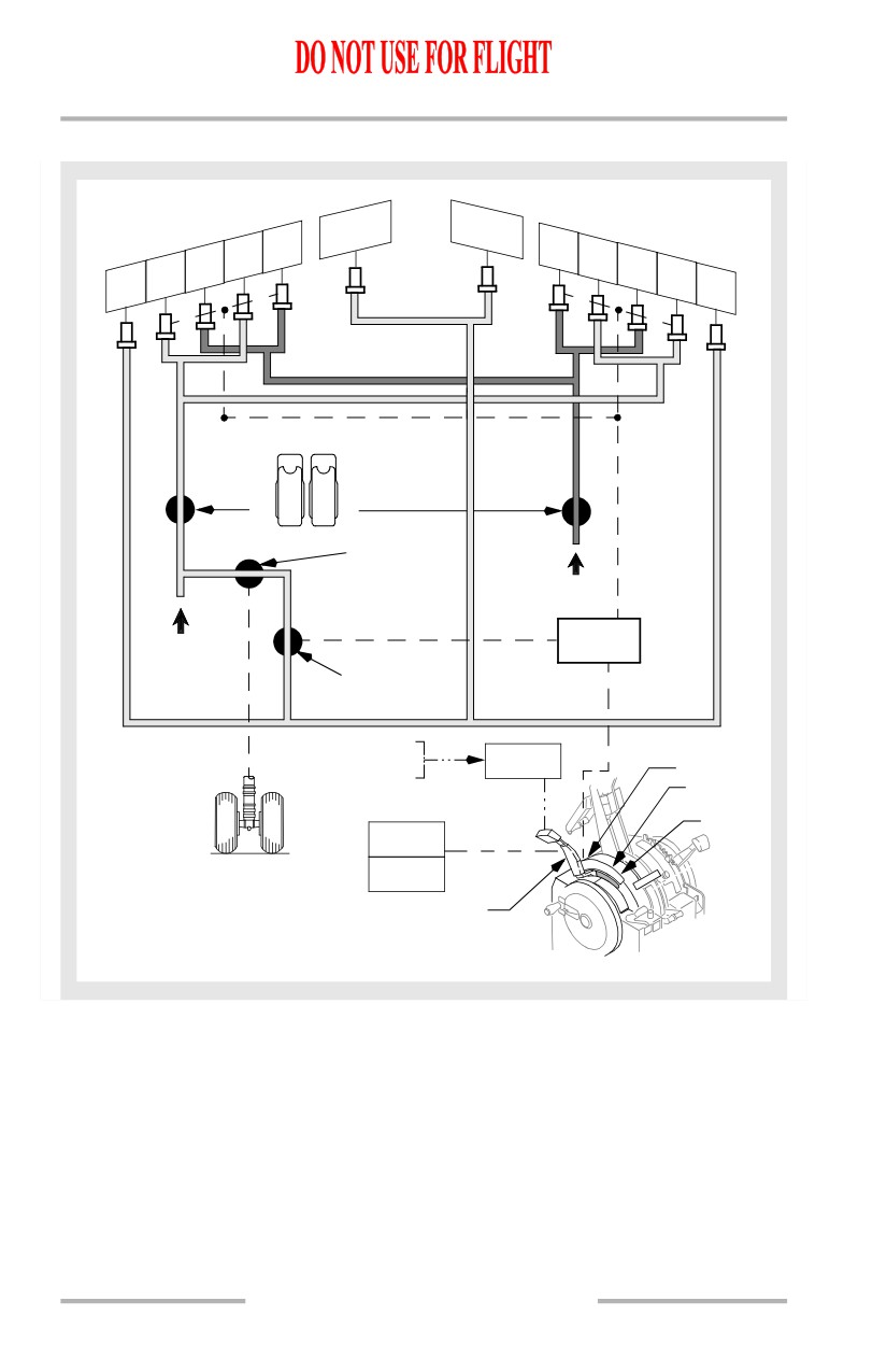
Speed Brakes
The speed brakes consist of flight spoilers and ground spoilers. Hydraulic system
A powers all four ground spoilers, two on the upper surface of each wing. The
SPEED BRAKE lever controls the spoilers. When the SPEED BRAKE lever is
actuated all the spoilers extend when the airplane is on the ground and only the
flight spoilers extend when the airplane is in the air.
The SPEEDBRAKES EXTENDED light provides an indication of spoiler
operation in-flight and on the ground. In-flight, the light illuminates to warn the
crew that the speed brakes are extended while in the landing configuration or
below 800 feet AGL. On the ground, the light illuminates when hydraulic pressure
is sensed in the ground spoiler shutoff valve with the speed brake lever in the
DOWN position.
In-Flight Operation
Operating the SPEED BRAKE lever in flight causes all flight spoiler panels to rise
symmetrically to act as speed brakes. Caution should be exercised when
deploying flight spoilers during a turn, as they greatly increase roll rate. When the
speed brakes are in an intermediate position roll rates increase significantly.
Moving the SPEED BRAKE lever beyond the FLIGHT DETENT causes
buffeting and is prohibited in flight.
Ground Operation
During landing, the auto speed brake system operates when these conditions
occur:
• SPEED BRAKE lever is in the ARMED position
• SPEED BRAKE ARMED light is illuminated
• radio altitude is less than 10 feet
• landing gear strut compresses on touchdown
Note: Compression of any landing gear strut enables the flight spoilers to
deploy. Compression of the right main landing gear strut enables the
ground spoilers to deploy.
• both thrust levers are retarded to IDLE
• main landing gear wheels spin up (more than 60 kts).
The SPEED BRAKE lever automatically moves to the UP position and the
spoilers deploy.
If a wheel spin-up signal is not detected, when the air/ground system senses
ground mode (any gear strut compresses) the SPEED BRAKE lever moves to the
UP position and flight spoiler panels deploy automatically. When the right main
landing gear strut compresses, a mechanical linkage opens the ground spoiler
shutoff valve and the ground spoilers deploy.
9.20.16
Flight Controls -
System Description
Boeing 737 Operations Manual
If the SPEED BRAKE lever is in the DOWN position during landing or rejected
takeoff, the auto speed brake system operates when these conditions occur:
• main landing gear wheels spin up (more than 60 kts)
• both thrust levers are retarded to IDLE
• reverse thrust levers are positioned for reverse thrust.
The SPEED BRAKE lever automatically moves to the UP position and spoilers
deploy.
After an RTO or landing, if either thrust lever is advanced, the SPEED BRAKE
lever automatically moves to the DOWN detent and all spoiler panels retract. The
spoiler panels may also be retracted by manually moving the SPEED BRAKE
lever to the DOWN detent.
9.20.17
Flight Controls -
System Description
Boeing 737 Operations Manual
Speed Brakes Schematic
6
7
5
8
4
9
3
10
2
11
1
12
SPOILER
A
B
OFF
OFF
ON
ON
GROUND SPOILER
SHUTOFF VALVE
B
SPOILER
A
MIXER
GROUND SPOILER
CONTROL VALVE
RADIO ALTITUDE
SPEEDBRAKES
FLAP POSITION
EXTENDED
ARMED
HYDRAULIC PRESSURE
FLIGHT
DETENT
UP
SPEED BRAKE
ARMED
RIGHT MAIN
SPEED BRAKE
LANDING GEAR
DO NOT ARM
SPEED BRAKE LEVER
FLIGHT SPOILERS: 2, 3, 4, 5, 8, 9, 10, 11
GROUND SPOILERS: 1, 6, 7, 12
9.20.18
Flight Controls -
System Description
Boeing 737 Operations Manual
Flaps and Slats
The flaps and slats are high lift devices that increase wing lift and decrease stall
speed during takeoff, low speed maneuvering and landing.
LE devices consist of four flaps and eight slats: two flaps inboard and four slats
outboard of each engine. Slats extend to form a sealed or slotted leading edge
depending on the TE flap setting. The TE devices consist of double slotted flaps
inboard and outboard of each engine.
TE flap positions 1-15 provide increased lift; positions 15-40 provide increased
lift and drag. Flap positions 30 and 40 are normal landing flap positions. Flaps 15
is used for some non-normal landing conditions.
To prevent excessive structural loads from increased Mach at higher altitude, flap
extension above 20,000 feet should not be attempted.
Flap and Slat Sequencing
LE devices and TE flaps are normally extended and retracted by hydraulic power
from system B. When the FLAP lever is in the UP detent, all flaps and LE devices
are commanded to the retracted or up position. Moving the FLAP lever aft allows
selection of flap detent positions 1, 2, 5, 10, 15, 25, 30 or 40. The LE devices
deployment is sequenced as a function of TE flaps deployment.
When the FLAP lever is moved from the UP position to the 1, 2, or 5 position, the
TE flaps extend to the commanded position and the LE:
• flaps extend to the full extended position and
• slats extend to the extend position.
When the FLAP lever is moved beyond the 5 position the TE flaps extend to the
commanded position and the LE:
• flaps remain at the full extended position and
• slats extend to the full extended position.
The LE devices sequence is reversed upon retraction.
Mechanical gates hinder inadvertent FLAP lever movement beyond flaps 1 for
one engine inoperative go-around and flaps 15 for normal go-around.
Indicator lights on the center instrument panel provide overall LE devices position
status. The LE DEVICES annunciator panel on the aft overhead panel indicates
the positions of the individual flaps and slats.
Flap Load Relief
The flaps/slat electronics unit (FSEU) provides a TE flap load relief function
which protects the flaps from excessive air loads. This function is operative at the
flaps 30 and flaps 40 positions only. The FLAP lever does not move, but the flap
position indicator displays flap retraction and re-extension.
9.20.19
Flight Controls -
System Description
Boeing 737 Operations Manual
When the flaps are set at 40, the TE flaps:
• retract to 30 if airspeed exceeds 163 knots
• re-extend when airspeed is reduced below 158 knots.
When the flaps are set at 30, the TE flaps:
• retract to 25 if the airspeed exceeds 176 knots
• re-extend when airspeed is reduced below 171 knots.
[Option]
The FLAP LOAD RELIEF light illuminates when the TE flap load relief function
is activated.
Autoslats
At flap positions 1, 2 and 5 an autoslat function is available that moves the LE slats
to full extended if the airplane approaches a stall condition.
The autoslat system is designed to enhance airplane stall characteristics at high
angles of attack during takeoff or approach to landing. When TE flaps 1 through
5 are selected, the LE slats are in the extend position. As the airplane approaches
the stall angle, the slats automatically drive to the full extended position prior to
stick shaker activation. The slats return to the extend position when the pitch angle
is sufficiently reduced below the stall critical attitude.
The autoslat system is designed to enhance airplane stall characteristics at high
angles of attack during takeoff or approach to landing. When TE flaps 1 through
5 are selected, the LE slats are in the extend position. As the airplane approaches
the stall angle, the slats automatically begin driving to the full extended position
prior to stick shaker activation. The slats return to the extend position when the
pitch angle is sufficiently reduced below the stall critical attitude.
Autoslat operation is normally powered by hydraulic system B. An alternate
source of power is provided by system A through a power transfer unit (PTU) if a
loss of pressure is sensed from the higher volume system B engine driven pump.
The PTU provides system A pressure to power a hydraulic motorized pump,
pressurizing system B fluid to provide power for the autoslat operation. (Refer to
Chapter 13, Hydraulics, Power Transfer Unit)
Alternate Extension
In the event that hydraulic system B fails, an alternate method of extending the LE
devices and extending and retracting the TE flaps is provided.
9.20.20
Flight Controls -
System Description
Boeing 737 Operations Manual
The TE flaps can be operated electrically through the use of two alternate flap
switches. The guarded ALTERNATE FLAPS master switch closes a flap bypass
valve to prevent hydraulic lock of the flap drive unit and arms the alternate flaps
position switch. The ALTERNATE FLAPS position switch controls an electric
motor that extends or retracts the TE flaps. The switch must be held in the DOWN
position until the flaps reach the desired position. No asymmetry or skew
protection is provided through the alternate (electrical) flap drive system.
When using alternate flap extension the LE flaps and slats are driven to the full
extended position using power from the standby hydraulic system. In this case the
ALTERNATE FLAPS master switch energizes the standby pump and the
ALTERNATE FLAPS position switch, held in the down position momentarily,
fully extends the LE devices.
Note: The LE devices cannot be retracted by the standby hydraulic system.
9.20.21