Boeing 737 - 600/700/800/900. Operations Manual (1997 year) - page 39
Fire Protection -
System Description
Boeing 737 Operations Manual
Extinguisher Test
When the EXT TEST switch is positioned to 1 or 2, the green EXT TEST lights
illuminate, verifying circuit continuity from the squib to the engine fire warning
switch.
Cargo Fire System Tests
The cargo fire detection and suppression system can be tested by pushing and
holding the cargo fire TEST switch. This sends a test signal to the forward and aft
cargo fire detector loops and verifies continuity of the extinguisher bottle squib
circuits. All test indications clear when the TEST switch is released
Cargo Fire TEST
The indications for the Cargo Fire test are:
• the fire warning bell sounds
• both master FIRE WARN lights illuminate
• the extinguisher test lights illuminate
• the FWD and AFT cargo fire warning lights illuminate when all detectors
in selected loops (s) respond to the fire test
• the cargo fire bottle DISCH light illuminates
Note: The fire warning BELL CUTOUT switch on the Overheat/Fire Protection
panel can silence the fire warning bell and extinguish the master FIRE
WARN lights
Note: During a Cargo Fire Test, the DETECTOR Fault light will illuminate if one
or more detectors in the loop(s) has failed.
Note: Individual detector faults can only be detected by a manually initiated test.
The MASTER CAUTION light does not illuminate.
Note: At the end of cargo fire testing, up to a four second delay may occur to
allow all applicable indications to extinguish at the same time.
Cargo Fire Extinguisher Test
When the Cargo Fire TEST button is pushed, the green EXT lights illuminate,
verifying the fire bottle discharge squib circuit continuity is normal.
8.20.8
Boeing 737 Operations Manual
Flight Controls
Chapter 9
Table of Contents
Section 0
9.0 Flight Controls-Table of Contents
Controls and Indicators
9.10.1
Flight Control Panel
9.10.1
Stabilizer
9.10.5
Rudder
9.10.7
Aileron / Elevator / Flight Spoilers
9.10.8
Speed Brakes
9.10.9
Trailing Edge Flaps
9.10.11
Leading Edge Devices
9.10.13
Flight Control Surface Position Indicator
9.10.14
System Description
9.20.1
Introduction
9.20.1
Pilot Controls
9.20.1
Flight Control Surfaces
9.20.2
Flight Control Surfaces Location
9.20.2
Roll Control
9.20.4
Ailerons
9.20.4
Flight Spoilers
9.20.5
Roll Control Schematic
9.20.6
Pitch Control
9.20.7
Elevators
9.20.7
Stabilizer
9.20.8
Pitch Control Schematic
9.20.10
Stall Identification
9.20.11
Yaw Control
9.20.12
Rudder
9.20.12
Yaw Damper
9.20.13
Yaw Control Schematic
9.20.14
Speed Brakes
9.20.16
9.TOC.0.1
Flight Controls -
Table of Contents
Boeing 737 Operations Manual
In-Flight Operation
9.20.16
Ground Operation
9.20.16
Speed Brakes Schematic
9.20.18
Flaps and Slats
9.20.19
Flap and Slat Sequencing
9.20.19
Flap Load Relief
9.20.19
Autoslats
9.20.20
Alternate Extension
9.20.20
Asymmetry and Skew Detection, Protection and
Indication
9.20.23
Uncommanded Motion Detection, Protection and
Indication
9.20.23
9.TOC.0.2
Boeing 737 Operations Manual
Flight Controls
Chapter 9
Controls and Indicators
Section 10
Flight Control Panel
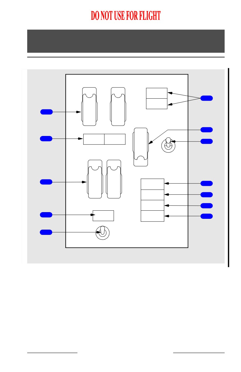
FLT CONTROL
STANDBY
A
B
HYD
LOW
QUANTITY
STBY
STBY
6
RUD
RUD
LOW
PRESSURE
OFF
OFF
1
A ON
B ON
ALTERNATE FLAPS
OFF
7
UP
LOW
LOW
2
PRESSURE
PRESSURE
8
OFF
SPOILER
DOWN
A
B
ARM
OFF
OFF
3
FEEL
9
DIFF PRESS
ON
ON
SPEED TRIM
FAIL
10
MACH TRIM
YAW DAMPER
FAIL
11
YAW
AUTO SLAT
4
12
DAMPER
FAIL
OFF
5
ON
FORWARD OVERHEAD PANEL
9.10.1
Flight Controls -
Controls and Indicators
Boeing 737 Operations Manual
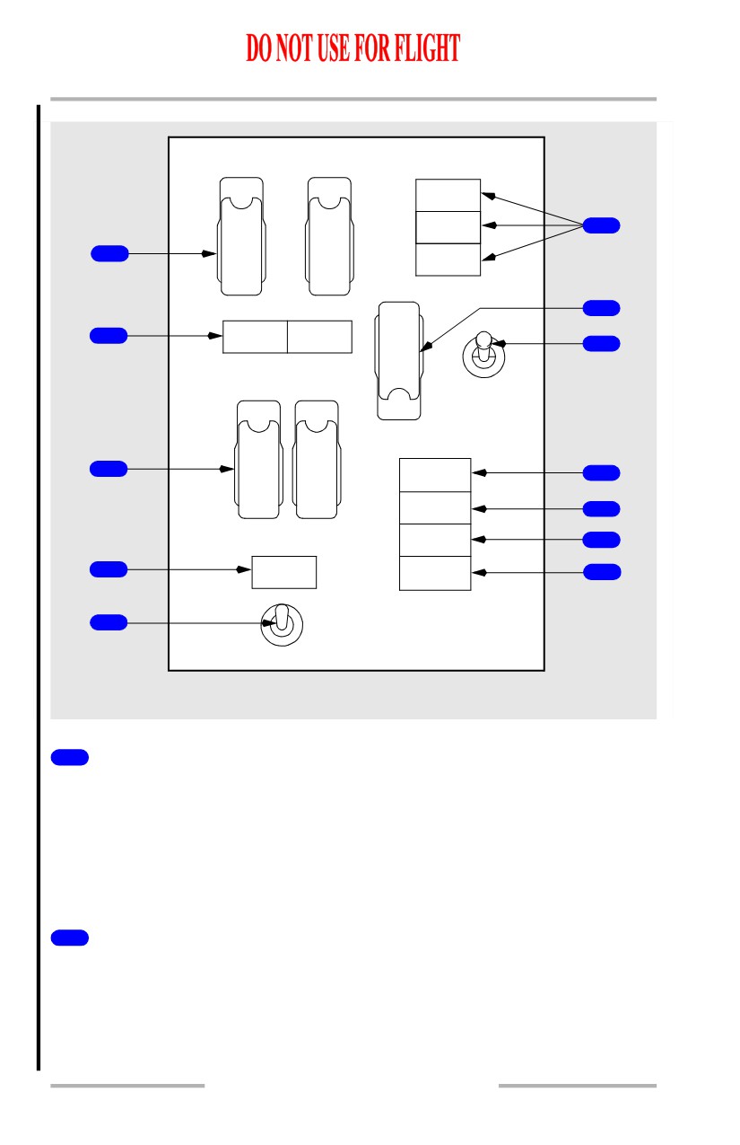
[Flight Control Panel for 737 modified rudder system.]
FLT CONTROL
STANDBY
A
B
HYD
LOW
QUANTITY
STBY
STBY
RUD
RUD
LOW
6
PRESSURE
OFF
OFF
1
STBY
A ON
B ON
RUD ON
ALTERNATE FLAPS
OFF
7
UP
LOW
LOW
2
PRESSURE
PRESSURE
8
OFF
SPOILER
DOWN
A
B
ARM
OFF
OFF
3
FEEL
9
DIFF PRESS
ON
ON
SPEED TRIM
FAIL
10
MACH TRIM
YAW DAMPER
FAIL
11
4
YAW
AUTO SLAT
DAMPER
FAIL
12
OFF
5
ON
FORWARD OVERHEAD PANEL
1
FLIGHT CONTROL Switches
STBY RUD - activates standby hydraulic system pump and opens standby rudder
shutoff valve to pressurize standby rudder power control unit.
OFF - closes flight control shutoff valve isolating ailerons, elevators and rudder
from associated hydraulic system pressure.
ON (guarded position) - normal operating position.
2
Flight Control LOW PRESSURE Lights
Illuminated (amber) -
• indicates low hydraulic system (A or B) pressure to ailerons, elevator and
rudder
• deactivated when associated FLIGHT CONTROL switch is positioned to
STBY RUD and standby rudder shutoff valve opens.
9.10.2
Flight Controls -
Controls and Indicators
Boeing 737 Operations Manual
3
Flight SPOILER Switches
ON (guarded position) - normal operating position.
OFF - closes the respective flight spoiler shutoff valve.
Note: Used for maintenance purposes only.
4
YAW DAMPER Light
Illuminated (amber) - yaw damper is not engaged.
5
YAW DAMPER Switch
OFF - disengages yaw damper.
ON -
• engages main yaw damper to main rudder power control unit if the B FLT
CONTROL switch is in the ON position
• engages standby yaw damper to standby rudder power control unit if both
the A and B FLT CONTROL switches are in the STBY RUD position.
6
STANDBY HYD Lights
STANDBY HYDRAULIC LOW QUANTITY Light
Illuminated (amber) -
• indicates low quantity in standby hydraulic reservoir
• always armed.
STANDBY HYDRAULIC LOW PRESSURE Light
Illuminated (amber) -
• indicates output pressure of standby pump is low
• armed only when standby pump operation has been selected or automatic
standby function is activated.
STBY RUD ON Light
• Illuminated (amber) - indicates the standby rudder PCU is pressurized.
7
ALTERNATE FLAPS Master Switch
OFF (guarded position) - normal operating position.
ARM - closes TE flap bypass valve, activates standby pump, and arms the
ALTERNATE FLAPS position switch.
8
ALTERNATE FLAPS Position Switch
Functions only when the ALTERNATE FLAPS master switch is in ARM.
9.10.3
Flight Controls -
Controls and Indicators
Boeing 737 Operations Manual
UP -
• electrically retracts TE flaps
• LE devices remain extended and cannot be retracted by the alternate flaps
system.
OFF - normal operating position.
DOWN (spring loaded to OFF) -
•
(momentary) fully extends LE devices using standby hydraulic pressure
•
(hold) electrically extends TE flaps until released.
9
Feel Differential Pressure (FEEL DIFF PRESS) Light
Armed when the TE flaps are up or down.
Illuminated (amber) -
• indicates excessive differential pressure in the elevator feel computer.
Note: Excessive differential pressure can be caused by erroneous activation of
the Elevator Feel Shift module.
10
Speed Trim Failure (SPEED TRIM FAIL) Light
Illuminated (amber) -
• indicates failure of the speed trim system
• indicates failure of a single FCC channel when MASTER CAUTION
light recall is activated and light extinguishes when Master Caution
System is reset.
11
Mach Trim Failure (MACH TRIM FAIL) Light
Illuminated (amber) -
• indicates failure of the mach trim system
• indicates failure of a single FCC channel when MASTER CAUTION
light recall is activated and light extinguishes when master caution system
is reset.
12
Automatic Slat Failure (AUTO SLAT FAIL) Light
Illuminated (amber) -
• indicates failure of the auto slat system
• indicates failure of a single Stall Management/Yaw Damper (SMYD)
computer when illuminated during MASTER CAUTION recall and
extinguishes when master caution system is reset.
9.10.4
Flight Controls -
Controls and Indicators
Boeing 737 Operations Manual
Stabilizer
STAB
TRIM
APL
NOSE
1
DOWN
0
2
5
3
10
15
APL
NOSE UP
CONTROL STAND
STAB TRIM
4
MAIN
AUTO
OVERRIDE
ELECT
NORMAL
PILOT
5
6
7
CUT
NORM
OUT
CONTROL WHEEL
CONTROL STAND
AFT ELECTRONIC
PANEL
8
STAB
OUT
OF
CENTER
TRIM
FORWARD
PANEL
1
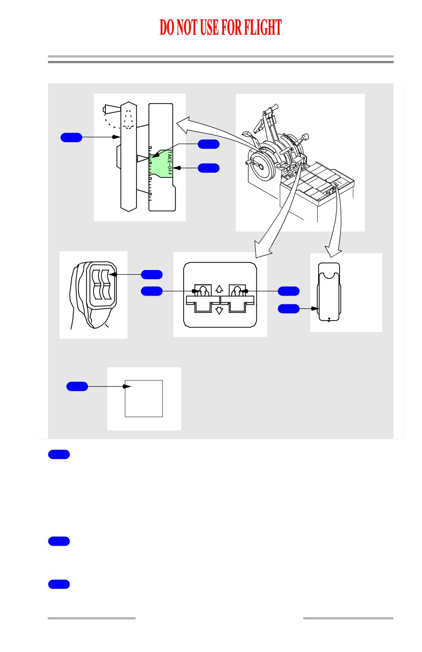
Stabilizer Trim Wheel
• provides for manual operation of stabilizer
• overrides any other stabilizer trim inputs
• rotates when stabilizer is in motion.
Note: Handle should be folded inside stabilizer trim wheel for normal operation
2
Stabilizer Trim Indicator
Indicates units of airplane trim on the adjacent scale.
3
Stabilizer Trim Green Band Range
Corresponds to allowable range of trim settings for takeoff.
9.10.5
Flight Controls -
Controls and Indicators
Boeing 737 Operations Manual
4
Stabilizer Trim Switches (spring-loaded to neutral)
Push (both) -
• electrically commands stabilizer trim in desired direction
• autopilot disengages if engaged.
5
Stabilizer Trim Main Electric (MAIN ELECT) Cutout Switch
NORMAL - normal operating position.
CUTOUT - deactivates stabilizer trim switch operation.
6
Stabilizer Trim AUTOPILOT Cutout Switch
NORMAL - normal operating position.
CUTOUT -
• deactivates autopilot stabilizer trim operation
• autopilot disengages if engaged.
7
Stabilizer Trim Override Switch
OVERRIDE - bypasses the control column actuated stabilizer trim
cutout
switches to restore power to the Stabilizer Trim Switches
NORM (guarded position) - normal operating position.
8
Stabilizer Out of Trim (STAB OUT OF TRIM) Light
Refer to Chapter 4 - Automatic Flight
9.10.6
Flight Controls -
Controls and Indicators
Boeing 737 Operations Manual
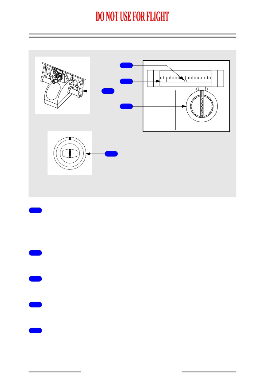
Rudder
2
RUDDER TRIM
15
10
5
0
5
10
15
OFF
3
LEFT
UNITS
RIGHT
1
NOSE
NOSE
LEFT
RIGHT
4
CREW STATION
AFT ELECTRONIC PANEL
5
CENTER FORWARD
PANEL
1
Rudder Pedals
Push -
• controls rudder position
• permits limited nose gear steering up to 7 degrees each side of center.
2
Rudder Trim Indicator
Indicates units of rudder trim.
3
Rudder Trim OFF Flag
Illuminated (amber) (in view) - rudder trim indicator is inoperative.
4
Rudder Trim Control (spring-loaded to neutral)
Rotate - electrically trims the rudder in the desired direction.
5
YAW DAMPER Indicator
• Indicates main yaw damper movement of rudder
• pilot rudder pedal inputs are not indicated.
9.10.7
Flight Controls -
Controls and Indicators
Boeing 737 Operations Manual
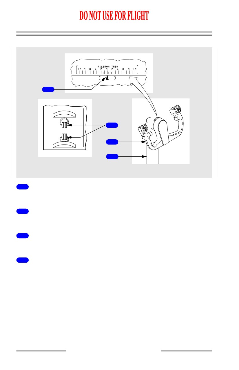
Aileron / Elevator / Flight Spoilers
1
AILERON
2
LEFT
RIGHT
WING
WING
DOWN
DOWN
3
4
AFT ELECTRONIC
PANEL
CREW STATION
1
AILERON TRIM Indicator
Indicates units of aileron trim.
2
AILERON Trim Switches (spring-loaded to the neutral position)
Movement of both switches repositions the aileron neutral control position.
3
Control Wheel
Rotate - operates ailerons and flight spoilers in desired direction.
4
Control Column
Push/Pull -
• operates elevators in the desired direction
• movement opposing stabilizer trim stops electric trimming.
9.10.8

Flight Controls -
Controls and Indicators
Boeing 737 Operations Manual
Speed Brakes
1
SPEED BRAKE
2
ARMED
SPEED BRAKE
DOWN
3
DO NOT ARM
ARMED
LEFT FORWARD
PANEL
FLIGHT
DETENT
SPEEDBRAKES
4
EXTENDED
UP
RIGHT FORWARD
CONTROL STAND
PANEL
1
SPEED BRAKE Lever
DOWN (detent) - all flight and ground spoiler panels in faired position.
ARMED -
• automatic speed brake system armed
• upon touchdown, the SPEED BRAKE lever moves to the UP position,
and all flight and ground spoilers extend.
FLIGHT DETENT - all flight spoilers are extended to their maximum position for
inflight use.
UP - all flight and ground spoilers are extended to their maximum position for
ground use.
2
SPEED BRAKE ARMED Light
Light deactivated when SPEED BRAKE lever is in the DOWN position.
Illuminated (green) - indicates valid automatic speed brake system inputs.
3
SPEED BRAKE DO NOT ARM Light
Light deactivated when SPEED BRAKE lever is in the DOWN position.
9.10.9
Flight Controls -
Controls and Indicators
Boeing 737 Operations Manual
Illuminated (amber) -
• indicates abnormal condition or test inputs to the automatic speed brake
system
4
SPEEDBRAKES EXTENDED Light
Illuminated (amber) -
• in-flight -
• SPEED BRAKE lever is beyond the ARMED position, and
• TE flaps extended more than flaps 10, or
• radio altitude less than 800 feet
• on the ground -
• SPEED BRAKE lever is in the DOWN detent,
• ground spoilers are not stowed.
Note: On the ground, the SPEEDBRAKES EXTENDED light does not
illuminate when hydraulic system A pressure is less than 750 psi.
9.10.10
Flight Controls -
Controls and Indicators
Boeing 737 Operations Manual
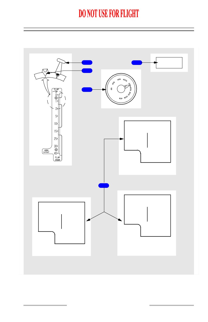
Trailing Edge Flaps
[Option - FLAP LOAD RELIEF light]
FLAP LOAD
1
5
RELIEF
2
2
5
RIGHT FORWARD
1
10
PANEL
UP
15
3
FLAPS
25
30
40
FLAPS LIMIT (IAS)
1-250K
15-185K
2-250K
25-175K
5-250K
30-160K
10-210K
40-155K
230K ALT FLAP
EXTEND
737-600
CONTROL STAND
4
FLAPS LIMIT (IAS)
FLAPS LIMIT (IAS)
1-250K
15-200K
2-250K
25-190K
1-250K
15-195K
5-250K
30-175K
2-250K
25-170K
10-210K
40-162K
5-250K
30-165K
230K ALT FLAP
10-210K
40-156K
EXTEND
230K ALT FLAP
EXTEND
737-800/700IGW/
737-700
737-900
CENTER FORWARD PANEL
9.10.11
Flight Controls -
Controls and Indicators
Boeing 737 Operations Manual
1
FLAP Lever
• selects position of flap control valve, directing hydraulic pressure for flap
drive unit
• position of the LE devices is determined by selecting TE flap position
• flap positions 30 and 40 arm the flap load relief system.
2
Flap Gates
Prevents inadvertent flap lever movement beyond:
• position 1 - to check flap position for one engine inoperative go-around
• position 15 - to check flap position for normal go-around.
3
Flap Position Indicator
• indicates position of left and right TE flaps
• provides TE flaps asymmetry and skew indication.
4
FLAPS LIMIT Placard
Indicates maximum speed for each flap setting.
5
FLAP LOAD RELIEF Light
[Option]
Illuminated (amber) -
• if flaps are set at 40:
• flaps retract to 30 due to excess airspeed or
• if flaps are set at 30:
• flaps retract to 25 due to excess airspeed.
9.10.12
Flight Controls -
Controls and Indicators
Boeing 737 Operations Manual
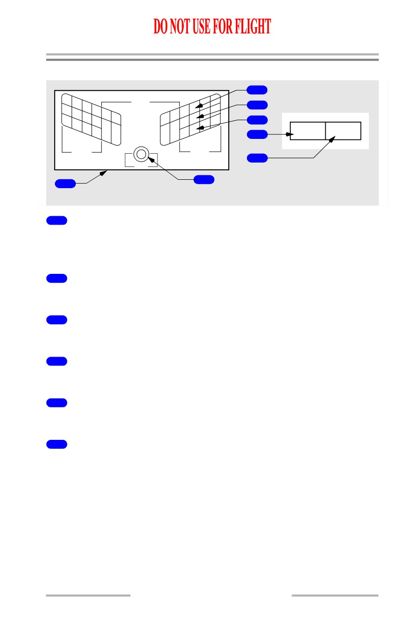
Leading Edge Devices
2
LE DEVICES
FLAPS
1
4
3
2
3
TRANSIT
4
LE FLAPS
LE FLAPS
1
EXT
8
2
7
6
TRANSIT
EXT
3
FULL EXT
6
4
5
SLATS
SLATS
7
TEST
CENTER FORWARD
5
PANEL
1
AFT OVERHEAD PANEL
1
Leading Edge Devices (LE DEVICES) Annunciator Panel
Indicates position of individual LE flaps and slats.
Extinguished - related LE device retracted.
2
Leading Edge Devices TRANSIT Lights
Illuminated (amber) - related LE device in transit.
3
Leading Edge Devices Extended (EXT) Lights
Illuminated (green) - related LE slat in extended (intermediate) position.
4
Leading Edge Devices Full Extended (FULL EXT) Lights
Illuminated (green) - related LE device fully extended.
5
Leading Edge Annunciator Panel TEST Switch
Press - tests all annunciator panel lights.
6
Leading Edge Flaps Transit (LE FLAPS TRANSIT) Light
Illuminated (amber) -
• any LE device in transit
• any LE device not in programmed position with respect to TE flaps
• a LE slat skew condition exists (slats 2 through 7 only)
• during alternate flap extension until LE devices are fully extended and TE
flaps reach approximately flaps 15.
Note: Light is inhibited during autoslat operation in flight.
9.10.13
Flight Controls -
Controls and Indicators
Boeing 737 Operations Manual
7
Leading Edge Flaps Extended (LE FLAPS EXT) Light
Illuminated (green) -
• all LE flaps extended and all LE slats in extended (intermediate) position
(TE flap positions 1, 2 and 5)
• all LE devices fully extended (TE flap positions 10 through 40).
Flight Control Surface Position Indicator
[Option]
MFD
ENG SYS
1
CENTER FORWARD PANEL
2
FLT
FLT
3
SPLR
SPLR
AIL
ELEV
AIL
4
5
RUDDER
LOWER DISPLAY UNIT
1
MFD System (SYS) Switch
Push - SYS
• displays flight control surface position indications on lower DU; or if the
lower DU is unavailable, displays it on upper DU or inboard DU based on
the position of the display select panel selector
• second push removes indications on the respective DU.
2
Flight Spoilers (FLT SPLR) (white)
Indicates related (left/right) flight spoilers position:
• top mark depicts flight spoilers fully deployed
• bottom mark depicts the spoilers down.
9.10.14
Flight Controls -
Controls and Indicators
Boeing 737 Operations Manual
3
Aileron (AIL) (white)
Indicates related (left/right) aileron position:
• top mark depicts maximum up position
• center mark depicts neutral position
• bottom mark depicts maximum down position.
4
Elevator (ELEV) (white)
Indicates elevator position:
• top mark depicts maximum up position
• center mark depicts neutral position when on the ground and trimmed in
the green band
• bottom mark depicts maximum down position.
Note: Elevator neutral position varies with stabilizer position, flap position and
Mach. The center index mark is set for nominal takeoff conditions. With
certain airplane nose up trim settings, the pointer will be somewhat
displaced.
5
RUDDER (white)
Indicates rudder position:
• left mark depicts maximum left position
• center mark depicts neutral position
• right mark depicts maximum right position.
9.10.15
Flight Controls -
Controls and Indicators
Boeing 737 Operations Manual
Intentionally
Blank
9.10.16
Boeing 737 Operations Manual
Flight Controls
Chapter 9
System Description
Section 20
Introduction
The primary flight control system uses conventional control wheel, column and
pedals linked mechanically to hydraulic power control units which command the
primary flight control surfaces; ailerons, elevators and rudder. The flight controls
are powered by redundant hydraulic sources; system A and system B. Either
hydraulic system can operate all primary flight controls. The ailerons and
elevators may be operated manually if required. The rudder may be operated by
the standby hydraulic system if system A and system B pressure is not available.
The secondary flight controls, high lift devices consisting of trailing edge (TE)
flaps and leading edge (LE) flaps and slats (LE devices), are powered by hydraulic
system B. In the event hydraulic system B fails, the TE flaps can be operated
electrically. Under certain conditions the power transfer unit (PTU) automatically
powers the LE devices. (Refer to Chapter 13, Hydraulics, Power Transfer Unit).
They can also be extended using standby hydraulic pressure.
Pilot Controls
The pilot controls consist of:
• two control columns
• AILERON trim switches
• two control wheels
• RUDDER trim control
• two pairs of rudder pedals
• YAW DAMPER switch
• SPEED BRAKE lever
• ALTERNATE FLAPS master
• FLAP lever
switch
• STAB TRIM cutout switches
• alternate flaps position switch
• STAB TRIM override switch
• FLT CONTROL switches
• stabilizer trim switches
• flight SPOILER switches
• stabilizer trim wheel
The columns and wheels are connected through transfer mechanisms which allow
the pilots to bypass a jammed control or surface.
There is a rigid connection between both pairs of rudder pedals.
The SPEED BRAKE lever allows manual or automatic symmetric actuation of the
spoilers.
9.20.1