Boeing 737 - 600/700/800/900. Operations Manual (1997 year) - page 41
Flight Controls -
System Description
Boeing 737 Operations Manual
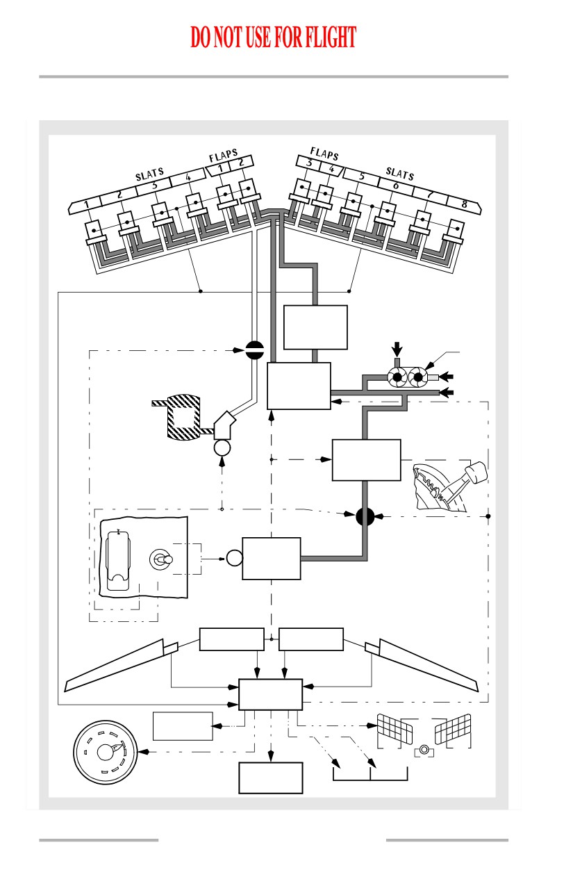
Leading Edge Devices and Trailing Edge Flaps Schematic
[Option - FLAP LOAD RELIEF light]
AUTOSLAT
CONTROL
FROM SYS B
RESERVOIR
VALVE
PTU
LE
SYS A
CONTROL
SYS B
STBY
RES
M
TE FLAP
CONTROL
ALTERNATE FLAPS
TE FLAP
OFF
BYPASS VALVE
UP
TE
OFF
M
DRIVE
UNIT
ARMDOWN
TE FLAPS
FSEU
LE DEVICES
1
FLAPS
4
FLAP LOAD
2
3
2
5
TRANSIT
1
RELIEF
1
2
EXT
7
8
10
3
4
FULL EXT
5
6
SLATS
SLATS
UP
15
TEST
FLAPS
25
30
LE FLAPSLE FLAPS
40
TRANSIT
EXT
SMYD
9.20.22
Flight Controls -
System Description
Boeing 737 Operations Manual
Asymmetry and Skew Detection, Protection and Indication
The FSEU monitors the TE flaps for asymmetry and skew conditions. It also
monitors the LE devices for improper position and skew conditions on slats 2
through 7. If a flap on one wing does not align with the symmetrical flap on the
other wing, there is a flap asymmetry condition. A skew condition occurs when a
TE flap or LE slat panel does not operate at the same rate causing the panel to twist
during extension or retraction.
Trailing Edge Flap Asymmetry and Skew
When the FSEU detects a trailing edge asymmetry or skew condition the FSEU:
• closes the TE flap bypass valve
• displays a needle split on the flap position indicator.
Leading Edge Device Improper Position or Skew
When the FSEU detects a LE device in an improper position or a LE slat skew
condition, the LE FLAPS TRANSIT light remains illuminated and one of the
following indications is displayed on the LE DEVICES annunciator panel:
• amber TRANSIT light illuminated
• incorrect green EXT or FULL EXT light illuminated
• no light illuminated.
There is no skew detection of the outboard slats, 1 and 8, or for the LE flaps. Slat
skew detection is inhibited during autoslat operations.
Uncommanded Motion Detection, Protection and Indication
The FSEU provides protection from uncommanded motion by the LE devices or
TE flaps.
Leading Edge Uncommanded Motion
Uncommanded motion is detected when no TE flap position or autoslat command
is present and:
• two LE flaps move on one wing, or
• two or more slats move on one wing.
The FSEU shuts down the LE control and illuminates the amber LE FLAPS
TRANSIT light.
In addition, to prevent uncommanded motion from occurring on the LE devices
during cruise, the FSEU maintains pressure on the retract lines and depressurizes
the extend and full extend lines.
9.20.23
Flight Controls -
System Description
Boeing 737 Operations Manual
Trailing Edge Uncommanded Motion
Uncommanded motion is detected when no FLAP lever or flap load relief
command is present and the TE flaps:
• move away from the commanded position
• continue to move after reaching a commanded position, or
• move in a direction opposite to that commanded.
The FSEU shuts down the TE drive unit by closing the TE flap bypass valve. The
TE flap shutdown cannot be reset by the flight crew and they must use the alternate
flap system to control TE flaps. The shutdown is indicated by the flap position
indicator disagreeing with the FLAP lever position. There is no flap needle split.
9.20.24
Boeing 737 Operations Manual
Flight Instruments, Displays
Chapter 10
Table of Contents
Section 0
10.0 Flight Instruments, Displays-Table of Contents
EFIS/Map - Controls and Indicators
10.10.1
EFIS/Map Display System - Overview
10.10.1
Captain Outboard Display
10.10.2
Captain Inboard Display
10.10.3
First Officer Inboard Display
10.10.4
First Officer Outboard Display
10.10.5
Compact EFIS Format
10.10.6
Electronic Flight Instrument System (EFIS) -
Mach/Airspeed Indicator (MASI)
10.10.7
Mach/Airspeed Indicator - General
10.10.7
Mach/Airspeed Indicator - Takeoff
10.10.9
Mach/Airspeed Indicator - Approach
10.10.11
Mach/Airspeed Indicator - IAS Disagree Alert
10.10.12
Mach/Airspeed Indicator Failure Flags
10.10.12
EFIS - Attitude Indicator
10.10.13
Attitude Indicator - General
10.10.13
Attitude Indicator - LNAV/VNAV Deviation
Indicators
10.10.15
Attitude Indicator - Instrument Landing System
Indications
10.10.17
Expanded Localizer Indications
10.10.19
Attitude Indicator Failure Flags
10.10.20
Traffic Alert and Collision Avoidance Indications
10.10.21
GPWS Annunciations
10.10.22
EFIS - Altimeter
10.10.22
Altimeter - General
10.10.22
Altimeter - Altitude Disagree Alert
10.10.24
Altimeter Failure Flag
10.10.24
EFIS - Vertical Speed Indicator
10.10.25
Vertical Speed Indicator - General
10.10.25
Vertical Speed Indicator Failure Flag
10.10.26
10.TOC.0.1
Flight Instruments, Displays -
Table of Contents
Boeing 737 Operations Manual
EFIS - Marker Beacon Indications
10.10.26
Marker Beacons Indications
10.10.26
Navigation Displays - Horizontal Situation Indicator
(HSI)
10.10.27
Horizontal Situation Indicator - General
10.10.27
Horizontal Situation Indicator - Compact Display
10.10.28
Horizontal Situation Indicator Failure Flags
10.10.29
Navigation Displays - Radio Distance Magnetic
Indicator (RDMI)
10.10.30
Radio Distance Magnetic Indicator - General
10.10.30
Radio Distance Magnetic Indicator Failure Flags
10.10.31
Navigation Displays - MAP Mode
10.10.32
Expanded MAP Mode
10.10.32
Center MAP Mode
10.10.34
Navigation Displays - Approach Mode
10.10.36
Expanded Approach Mode
10.10.36
Center Approach Mode
10.10.37
Navigation Displays - VOR Mode
10.10.39
Expanded VOR Mode
10.10.39
Center VOR Mode
10.10.40
Navigation Displays - Plan Mode
10.10.41
Plan Mode
10.10.41
Navigation Displays - Advisory Messages
10.10.42
Mode/Frequency Disagree Annunciation
10.10.42
Navigation Advisory Messages
10.10.43
TCAS Messages
10.10.44
Look-Ahead Terrain Messages (GPWS)
10.10.45
Predictive Windshear System (PWS) Message
10.10.46
Navigation Displays -Failure Indications and Flags
10.10.47
Failure Flags - Expanded MAP, Center MAP,
Expanded APP, Expanded VOR Modes
10.10.47
Failure Flags - Center APP and Center VOR
Modes
10.10.49
Additional Flags and Annunciations
10.10.50
10.TOC.0.2
Flight Instruments, Displays -
Table of Contents
Boeing 737 Operations Manual
Displays Control Panel Annunciation
10.10.50
Display System Annunciations
10.10.51
Instrument Switch Annunciation
10.10.52
PFD/ND - Displays
10.11.1
PFD/ND Display System - Overview
10.11.1
Captain Outboard Display
10.11.2
Captain Inboard Display
10.11.3
First Officer Inboard Display
10.11.4
First Officer Outboard Display
10.11.5
Primary Flight Display (PFD)- PFD Airspeed
Indications
10.11.6
PFD Airspeed Indications - General
10.11.6
PFD Airspeed Indications - Takeoff and Approach
10.11.8
PFD Angle of Attack (AOA) Indications
10.11.11
Angle of Attack Indications - General
10.11.11
PFD - Attitude Indications
10.11.12
Attitude Indications - General
10.11.12
PFD LNAV/VNAV Deviation Indications
10.11.14
PFD Instrument Landing System Indications
10.11.16
Expanded Localizer Indications
10.11.18
PFD Radio Altitude Indications
10.11.18
Traffic Alert and Collision Avoidance Indications
10.11.19
GPWS Annunciations
10.11.20
PFD - Altitude Indications
10.11.21
Altitude Indications- General
10.11.21
PFD Barometric Indications
10.11.22
Landing Altitude/Minimums Indications
10.11.23
PFD - Vertical Speed Indications
10.11.25
Vertical Speed Indications - General
10.11.25
PFD - Heading and Track Indications
10.11.26
Heading and Track Indications- General
10.11.26
PFD Failure Flags
10.11.27
Additional Annunciations and Alerts
10.11.32
10.TOC.0.3
Flight Instruments, Displays -
Table of Contents
Boeing 737 Operations Manual
Displays Control Panel Annunciation
10.11.32
Display System Annunciations
10.11.33
Instrument Switch Annunciation
10.11.34
Airspeed Disagree Alert
10.11.35
Altitude Disagree Alert
10.11.36
Navigation Displays - MAP Mode
10.11.36
Expanded and Center MAP Modes
10.11.37
Navigation Displays - Approach Mode
10.11.39
Expanded and Center Approach Modes
10.11.39
Navigation Displays - VOR Mode
10.11.41
Expanded and Center VOR Modes
10.11.41
Navigation Displays - Plan Mode
10.11.43
Plan Mode
10.11.43
Navigation Displays - Advisory Messages
10.11.44
Navigation Advisory Messages
10.11.44
Mode/Frequency Disagree Annunciation
10.11.45
TCAS Messages
10.11.46
Look-Ahead Terrain Messages (GPWS)
10.11.47
Predictive Windshear System (PWS) Message
10.11.48
Navigation Displays - Failure Indications and Flags
10.11.49
Expanded MAP, Center MAP, Expanded APP,
Expanded VOR Modes
10.11.49
ND Failure Flags - Center APP and Center VOR
Modes
10.11.51
Head-Up Display System - Displays
10.12.1
System Components
10.12.1
Combiner Display
10.12.2
Primary (PRI) Mode Display
10.12.2
Approach Mode Displays
10.12.9
Failure Indications and Flags
10.12.11
Control Panel Display
10.12.11
10.TOC.0.4
Flight Instruments, Displays -
Table of Contents
Boeing 737 Operations Manual
EFIS Instruments - Controls and Indicators
10.15.1
EFIS Control Panel (EFIS/Map Display)
10.15.1
EFIS Control Panel Controls - Flight Instrument
Displays
10.15.1
EFIS Control Panel Controls - Navigation Displays
10.15.2
Displays Source Panel
10.15.4
Display Select Panels
10.15.5
Speed Reference Selector
10.15.6
Display Brightness Controls
10.15.7
Captain Brightness Controls
10.15.7
First Officer Brightness Controls
10.15.8
Standby Flight Instruments
10.15.10
Standby Magnetic Compass
10.15.10
Integrated Standby Flight Display
10.15.11
Standby Radio Magnetic Indicator
10.15.15
Clock
10.15.16
Clock Switch
10.15.18
Timer
10.15.18
Flight Recorder
10.15.19
EFIS Instruments (PFD) - Controls
10.16.1
EFIS Control Panel (PFD/ND Display)
10.16.1
EFIS Control Panel Controls - Flight Instrument
Displays
10.16.1
EFIS Control Panel Controls - Navigation Displays
10.16.2
Displays Source Panel
10.16.4
Display Select Panels
10.16.5
Speed Reference Selector
10.16.6
Display Brightness Controls
10.16.7
Captain Brightness Controls
10.16.7
First Officer Brightness Controls
10.16.8
Standby Flight Instruments
10.16.10
10.TOC.0.5
Flight Instruments, Displays -
Table of Contents
Boeing 737 Operations Manual
Standby Magnetic Compass
10.16.10
Integrated Standby Flight Display
10.16.11
Standby Radio Magnetic Indicator
10.16.15
Clock
10.16.16
Clock Switch
10.16.18
Timer
10.16.19
Flight Recorder
10.16.19
Head-Up Display System - Controls
10.17.1
Head-Up Display Control Panel Controls - Flight
Instrument Displays
10.17.1
HUD Annunciator Panel
10.17.2
Combiner Controls
10.17.3
EFIS/Map System Description
10.20.1
Introduction
10.20.1
Display Brightness Control
10.20.1
DISPLAYS SOURCE Panel
10.20.2
EFIS Control Panels
10.20.3
Display Select Panel
10.20.3
Display Selection and Control Examples
10.20.4
Normal Display Configuration
10.20.4
Display Unit Failure Automatic Switching
10.20.5
EFIS Control Panel
10.20.7
Outboard Display Switching
10.20.8
Inboard Display Switching
10.20.9
Lower Display Switching
10.20.11
Display System Information Sources
10.20.12
Air Data Inertial Reference System (ADIRS)
10.20.12
Standby Flight Instruments
10.20.13
Standby Magnetic Compass
10.20.13
Integrated Standby Flight Display (ISFD)
10.20.14
Standby Radio Magnetic Indicator
10.20.14
10.TOC.0.6
Flight Instruments, Displays -
Table of Contents
Boeing 737 Operations Manual
Clocks
10.20.15
Clock Switch
10.20.15
Flight Recorder
10.20.15
Aircraft Condition Monitoring System (ACMS)
10.20.15
PFD/ND System Description
10.21.1
Introduction
10.21.1
Display Brightness Control
10.21.1
DISPLAYS SOURCE Panel
10.21.2
EFIS Control Panels
10.21.3
Display Select Panel
10.21.3
Display Selection and Control Examples
10.21.4
Normal Display Configuration
10.21.4
Display Unit Failure Automatic Switching
10.21.5
EFIS Control Panel
10.21.7
Outboard Display Switching
10.21.8
Inboard Display Switching
10.21.9
Lower Display Switching
10.21.11
Display System Information Sources
10.21.12
Air Data Inertial Reference System (ADIRS)
10.21.12
Standby Flight Instruments
10.21.13
Standby Magnetic Compass
10.21.14
Integrated Standby Flight Display (ISFD)
10.21.14
Standby Radio Magnetic Indicator
10.21.15
Clocks
10.21.15
Clock Switch
10.21.15
Flight Recorder
10.21.15
Aircraft Condition Monitoring System (ACMS)
10.21.16
Head-Up Display System Description
10.22.1
Introduction
10.22.1
HUD Computer
10.22.1
Drive Electronics Unit
10.22.2
10.TOC.0.7
Flight Instruments, Displays -
Table of Contents
Boeing 737 Operations Manual
Overhead Unit (OHU)
10.22.2
Combiner
10.22.2
Control Panel
10.22.2
Annunciator Panel
10.22.2
Modes of Operation
10.22.2
Primary (PRI) Mode
10.22.3
AIII Approach Mode
10.22.4
IMC Mode
10.22.5
VMC Mode
10.22.5
TCAS Resolution Advisory
10.22.6
Failure Flags and Data Source Annunciations
10.22.6
Electronic Flight Instrument System (EFIS)
10.30.1
Introduction
10.30.1
Airspeed
10.30.1
Attitude
10.30.1
Steering Indications
10.30.2
Instrument Landing System Indications
10.30.2
Approach Minimums
10.30.3
Radio Altitude
10.30.3
Radio Altitude Alert
10.30.3
Altitude
10.30.3
Vertical Speed
10.30.4
Traffic Alert and Collision Avoidance (TCAS)
Indications
10.30.4
GPWS Warnings
10.30.4
Primary Flight Display (PFD)
10.31.1
Introduction
10.31.1
Airspeed
10.31.1
Attitude
10.31.2
Angle of Attack
10.31.2
10.TOC.0.8
Flight Instruments, Displays -
Table of Contents
Boeing 737 Operations Manual
Steering Indications
10.31.2
Instrument Landing System Indications
10.31.3
Approach Minimums
10.31.4
Radio Altitude
10.31.4
Altitude
10.31.4
Vertical Speed
10.31.5
Heading/Track Indications
10.31.5
Traffic Alert and Collision Avoidance (TCAS)
Indications
10.31.5
GPWS Warnings
10.31.5
Navigation Displays
10.40.1
Introduction
10.40.1
Horizontal Situation Indicator (HSI)
10.40.1
Radio Distance Magnetic Indicator (RDMI)
10.40.1
Navigation Display - MAP Mode
10.40.1
Navigation Data Points
10.40.1
VOR and Approach Modes
10.40.2
Plan Mode
10.40.2
Navigation Display Information
10.40.2
Heading
10.40.2
Track
10.40.2
Traffic
10.40.2
Weather Radar
10.40.2
Failure Flags and Messages
10.40.2
Navigation Display Symbology
10.40.3
Heading, Track, and Speed
10.40.3
Radio Navigation
10.40.5
MAP
10.40.7
Look-Ahead Terrain
10.40.15
Predictive Windshear
10.40.17
TCAS
10.40.18
10.TOC.0.9
Flight Instruments, Displays -
Table of Contents
Boeing 737 Operations Manual
PFD/ND Navigation Displays
10.41.1
Introduction
10.41.1
Map Mode
10.41.1
Navigation Data Points
10.41.1
VOR and Approach Modes
10.41.1
Plan Mode
10.41.1
ND Information
10.41.2
Heading
10.41.2
Track
10.41.2
Traffic
10.41.2
Weather Radar
10.41.2
Failure Flags and Messages
10.41.2
ND Symbology
10.41.2
Heading, Track, and Speed
10.41.3
Radio Navigation
10.41.5
Map
10.41.8
Look-Ahead Terrain
10.41.14
Predictive Windshear
10.41.16
TCAS
10.41.17
Head-Up Display System, Symbology
10.42.1
Introduction
10.42.1
Head-Up Guidance Display Symbology
10.42.1
TCAS Resolution Advisory
10.42.14
Failure Flags and Data Source Annunciations
10.42.15
10.TOC.0.10
Boeing 737 Operations Manual
Flight Instruments, Displays
Chapter 10
EFIS/Map - Controls and Indicators
Section 10
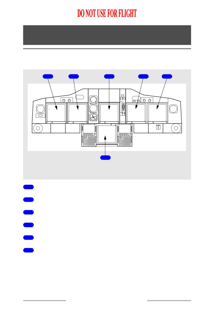
EFIS/Map Display System - Overview
Display Units
1
2
3
4
5
6
LEFT, CENTER and RIGHT
FORWARD PANELS
1
Captain Outboard Display Unit
2
Captain Inboard Display Unit
3
Upper Display Unit
4
First Officer Inboard Display Unit
5
First Officer Outboard Display Unit
6
Lower Display Unit
10.10.1
Flight Instruments, Displays -
EFIS/Map - Controls and
Indicators
Boeing 737 Operations Manual
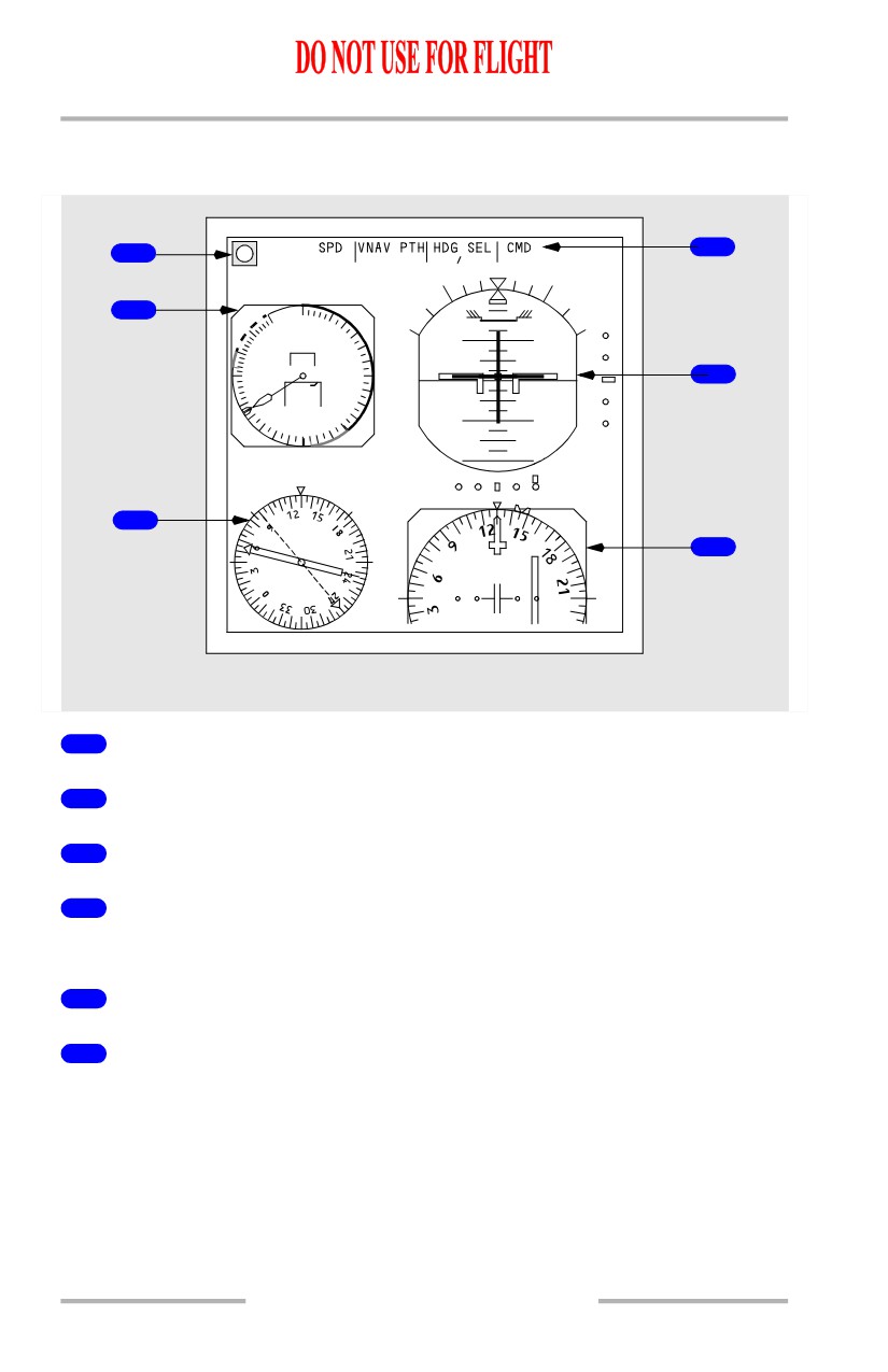
Captain Outboard Display
[Option - Split axis command bars]
1
OM
4
G/S
VOR LOC
2
60
80
400
100
10
10
350
.40
120
300
5
140
250
245
240
160
220
10
10
200180
UP
20
20
8.4
20.4
DME1
DME2
3
ILS
6
ADF1
VOR2
LEFT FORWARD PANEL
1
Marker Beacon
2
Mach/Airspeed Indicator
3
Radio Distance Magnetic Indicator
4
Flight Mode Annunciations
Refer to Chapter 4, Automatic Flight
5
Attitude Indicator
6
Horizontal Situation Indicator
10.10.2
Flight Instruments, Displays -
EFIS/Map - Controls and
Indicators
Boeing 737 Operations Manual
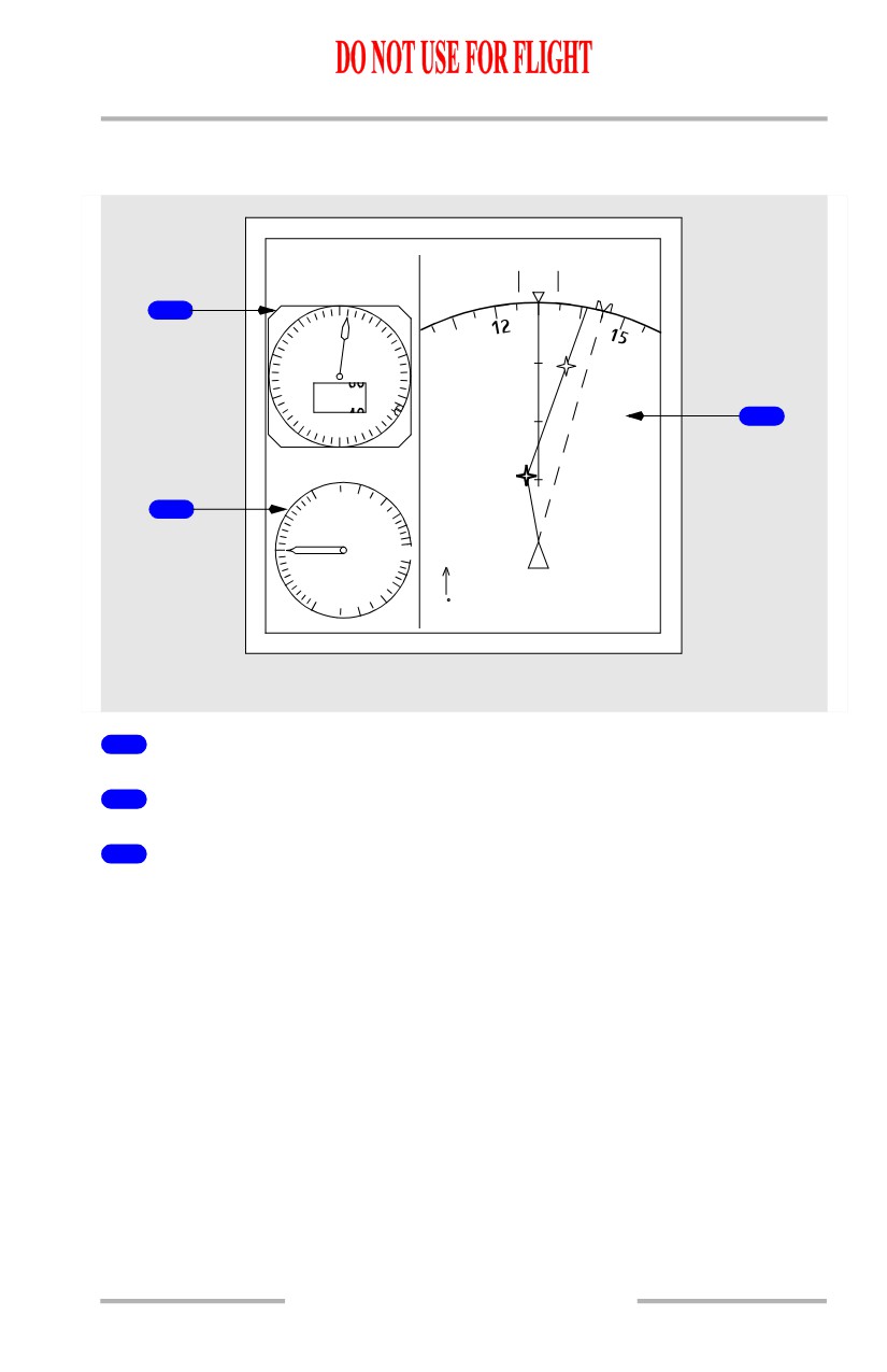
Captain Inboard Display
[Option - Heading-up display]
2.5 NM
Z
TAS
285
GS 295
HDG130
M
1
0
9
1
29.92 IN.
8
BEGGS
7
10020
3
6
4
5
3
5
RAGGS
1
2
2
.5
4
0
6
.5
4
1
2
310 /10
LEFT FORWARD PANEL
1
Altimeter
2
Vertical Speed Indicator
3
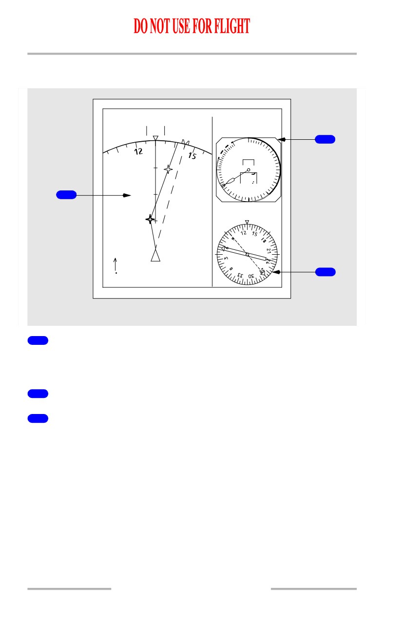
Navigation Display
Displays approach, VOR, moving map, or static map as selected on the EFIS
control panel.
10.10.3
Flight Instruments, Displays -
EFIS/Map - Controls and
Indicators
Boeing 737 Operations Manual
First Officer Inboard Display
[Option - Heading-up display]
2.5 NM
Z
TAS 285
GS 295
HDG130
M
2
60
80
400
100
350
.40
BEGGS
120
300
140
250
245
240
160
220200180
1
5
RAGGS
8.4
20.4
DME1
DME2
3
310 /10
ADF1
VOR2
RIGHT FORWARD PANEL
1
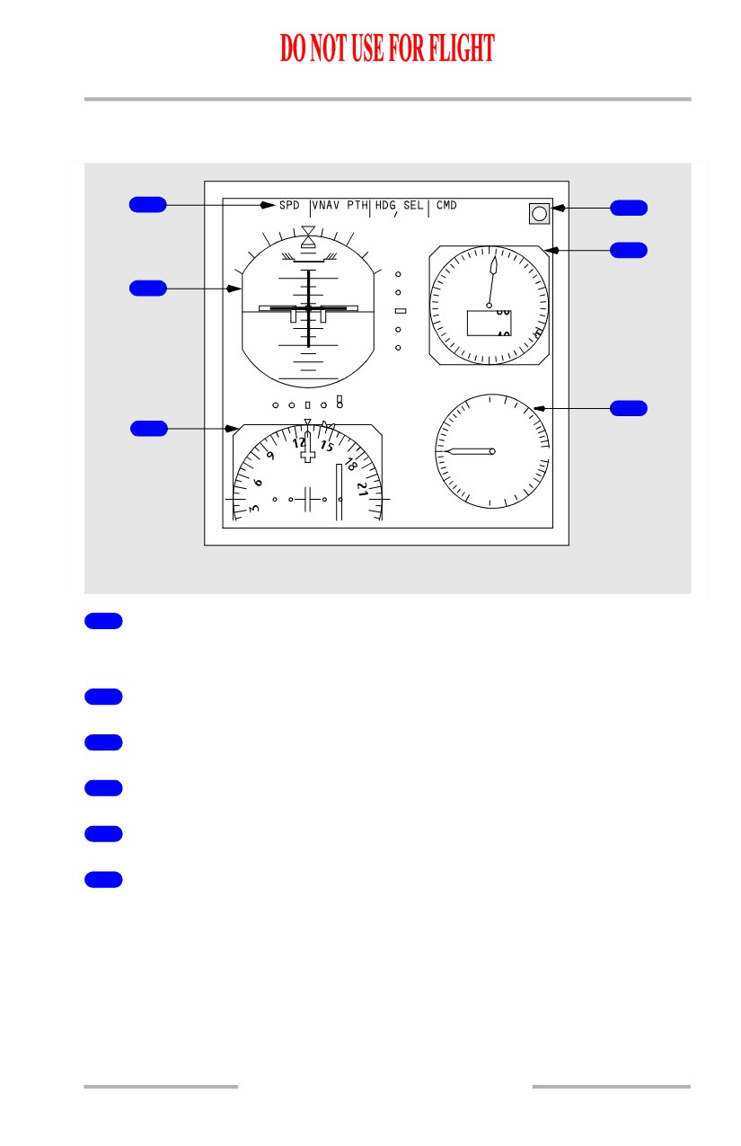
Navigation Display
Displays approach, VOR, moving map, or static map as selected on the EFIS
control panel.
2
Mach/Airspeed Indicator
3
Radio Distance Magnetic Indicator
10.10.4
Flight Instruments, Displays -
EFIS/Map - Controls and
Indicators
Boeing 737 Operations Manual
First Officer Outboard Display
[Option - Split axis command bars]
1
4
G/S
VOR LOC
OM
5
0
9
1
10
10
29.92 IN.
2
8
2
7
10 020
3
10
10
6
4
5
20
20
2
6
1
3
.5
4
ILS
0
6
.5
4
1
2
RIGHT FORWARD PANEL
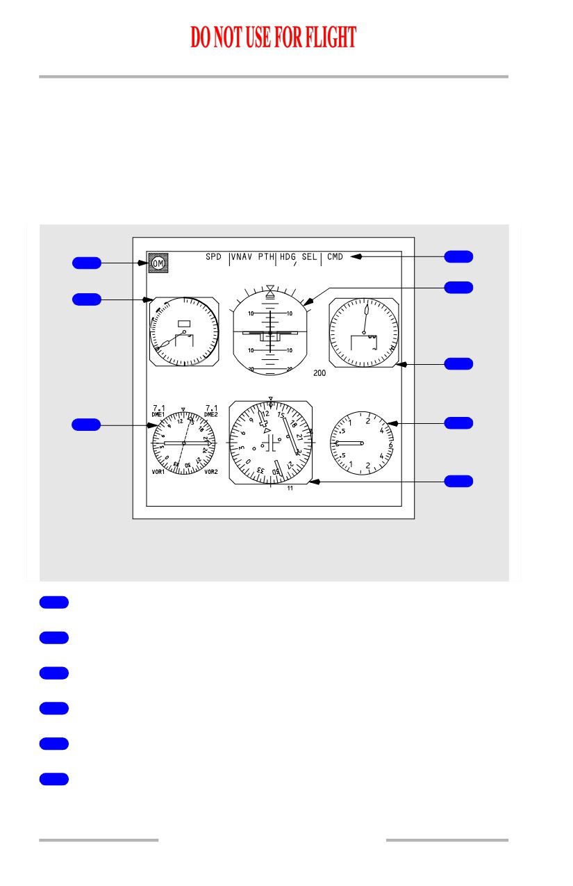
1
Flight Mode Annunciations
Refer to Chapter 4, Automatic Flight
2
Attitude Indicator
3
Horizontal Situation Indicator
4
Marker Beacon
5
Altimeter
6
Vertical Speed Indicator
10.10.5
Flight Instruments, Displays -
EFIS/Map - Controls and
Indicators
Boeing 737 Operations Manual
Compact EFIS Format
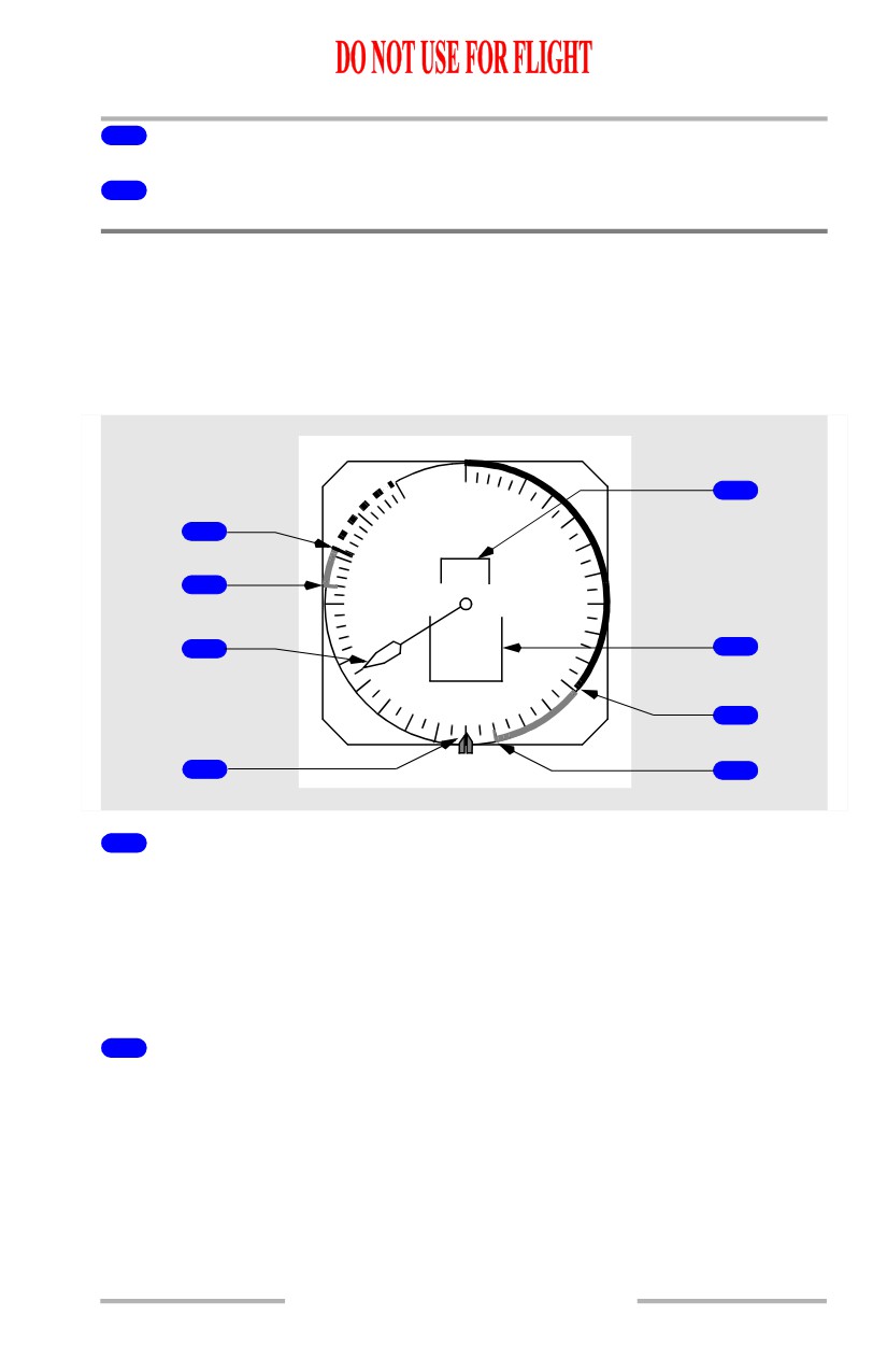
The compact EFIS format is displayed automatically upon failure of either an
inboard or an outboard display unit. The compact format can also be selected
manually with the MAIN PANEL DUs selectors on the display select panel.
In the compact format, a full rose HSI is displayed. Other displays are about 25%
smaller than normal.
[Option - Split axis command bars]
4
1
G/S
VOR LOC
5
2
60
80
0
400
100
9
1
350
29.92
IN.
.40
120
8
2
300
140
250
245
7
10 020
3
240
160
220
180
6
4
5
200
6
UP
RADIO
VOR
3
7
TO
8
HDG MAG
6.80
LEFT and RIGHT FORWARD PANELS
1
Marker Beacon
2
Mach/Airspeed Indicator
3
Radio Distance Magnetic Indicator
4
Flight Mode Annunciations
5
Attitude Indicator
6
Altimeter
10.10.6
Flight Instruments, Displays -
EFIS/Map - Controls and
Indicators
Boeing 737 Operations Manual
7
Vertical Speed Indicator
8
Horizontal Situation Indicator
Electronic Flight Instrument System (EFIS) -
Mach/Airspeed Indicator (MASI)
Mach/Airspeed Indicator - General
The mach/airspeed indicator displays air data inertial reference system (ADIRS)
airspeed and other airspeed related information.
60
5
80
1
400
100
350
.40
2
120
300
6
140
3
250
6
245
240
160
4
220
180
200
7
4
UP
8
1
Maximum Operating Speed (red and white)
Start of the arc indicates the maximum speed as limited by the lowest of the
following:
• Vmo/Mmo
• landing gear placard speed
• flap placard speed.
2
High Speed Buffet/Flap Extension Speed (amber)
At high altitudes and flaps up, the start of the arc indicates the airspeed that
provides a 0.3 g maneuver margin to high speed buffet.
When flaps are not up, the start of the arc indicates flap extension placard speed
for the next normal flap setting. The arc is removed when the flap handle is moved
to the landing flap selected on the APPROACH REF page or when the flap lever
has been moved to flaps 30 or 40.
10.10.7