Boeing 737 - 600/700/800/900. Operations Manual (1997 year) - page 35
Engines, APU -
Table of Contents
Boeing 737 Operations Manual
Oil Temperature Indications
7.11.13
Oil Quantity Indications
7.11.13
Engine Vibration Indications
7.11.14
Compact Engine Displays
7.11.15
General Controls and Indicators
7.15.1
Engine Start Switches
7.15.1
Engine Display Control Panel
7.15.3
Engine Panel
7.15.4
Engine Controls
7.15.6
APU
7.15.7
Engine System Description
7.20.1
Introduction
7.20.1
Engine Indications
7.20.1
Engine Indications
7.20.2
Primary Engine Indications
7.20.2
Secondary Engine Indications
7.20.2
Normal Display Format
7.20.3
Compact Display
7.20.4
Electronic Engine Control (EEC)
7.20.4
EEC Normal Mode
7.20.4
EEC Alternate Mode
7.20.5
Structural Limit Protection
7.20.6
Idle Operation
7.20.6
Power Plant Schematic
7.20.7
Engine Fuel System
7.20.8
Engine Oil System
7.20.8
Engine Fuel and Oil System Schematic
7.20.9
Engine Start System
7.20.10
Abnormal Start Protection (Ground Starts Only)
7.20.10
Engine Ignition System
7.20.11
Inflight Starting
7.20.11
7.TOC.0.2
Engines, APU -
Table of Contents
Boeing 737 Operations Manual
Engine Start and Ignition System Schematic
7.20.12
Thrust Reverser
7.20.14
Thrust Reverser Schematic
7.20.16
APU System Description
7.30.1
Introduction
7.30.1
APU Location
7.30.1
APU Operation
7.30.1
APU Fuel Supply
7.30.2
APU Engine and Cooling Air
7.30.2
Electrical Requirements for APU Operation
7.30.2
APU Start
7.30.2
APU Shutdown
7.30.3
Electronic Control Unit (ECU)
7.30.3
APU Automatic Load Shedding
7.30.3
7.TOC.0.3
Engines, APU -
Table of Contents
Boeing 737 Operations Manual
Intentionally
Blank
7.TOC.0.4
Boeing 737 Operations Manual
Engines, APU
Chapter 7
Side by Side - Displays
Section 10
Primary and Secondary Engine Indications
[Option - Side by side display, lbs]
A/T LIM
CRZ
TAT-
12
C
START VALVE
START VALVE
OPEN
OPEN
96.0
96.0
OIL FILTER
OIL FILTER
TAI
TAI
BYPASS
BYPASS
87.7
87.7
LOW OIL
LOW OIL
10
10
PRESSURE
PRESSURE
0
0
8
8
2
2
6
6
4
4
100
100
N1
50
50
0
0
663
663
OIL P
200
200
1
EGT
100
100
3
0
0
77.7
77.7
OIL T
95
95
OIL Q %
N2
3
3
2
2
4
4
12
12
1
1
11.27
11.27
5
5
0
0
0
0
VIB
8
8
4
FF/FU
4
A
B
LB X 1000
3
4
3
4
4
CTR
2
0
2
0
1
2
1
1
HYD P
2
24
000
8
600
8
600
95
95
FUEL LB
HYD Q %
UPPER DISPLAY UNIT
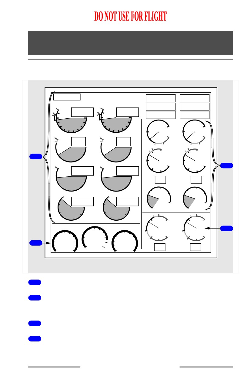
1
Primary Engine Indications
2
Fuel Quantity Indications
Refer to Chapter 12, Fuel.
3
Secondary Engine Indications
4
Hydraulic Indications
Refer to Chapter 13, Hydraulics.
7.10.1
Engines, APU -
Side by Side - Displays
Boeing 737 Operations Manual
Autothrottle Limit, Thrust Mode Display and
Total Air Temperature
1
A/T LIM
CRZ
TAT-12 C
3
2
UPPER DISPLAY UNIT
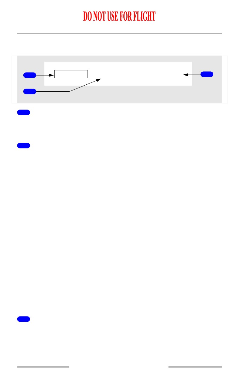
1
Autothrottle Limit (A/T LIM) Indication
Illuminated (white) - The FMC is not providing the A/T system with N1 limit
values. The A/T is using a degraded N1 thrust limit from the related EEC.
2
Thrust Mode Display
Displayed (green) - the active N1 limit reference mode.
With N1 manual select knob on engine display control panel in AUTO, active N1
limit is displayed by reference N1 bugs.
Active N1 limit is normally calculated by FMC.
Thrust mode display annunciations are:
• R-TO - reduced takeoff
• R-CLB - reduced climb
• TO - takeoff
[Option]
• TO B - takeoff bump thrust
• CLB - climb
• CRZ - cruise
• G/A - go-around
• CON - continuous
•
- - - - FMC not computing thrust limit.
Note: R-TO does not indicate the type of reduced takeoff. The N1 limit may be
reduced due to the entry of an assumed temperature, a takeoff thrust derate
or a combination of both assumed temperature and takeoff thrust derate.
3
Total Air Temperature (TAT) Indication
Displayed (label -cyan, temp - white) - total air temperature (degrees C).
7.10.2
Engines, APU -
Side by Side - Displays
Boeing 737 Operations Manual
N1 Indications
3
4
6
7
96.0
96.0
N1 SET
10
87.7
10
87.7
AUTO
1
BOTH
0
0
8
8
2
2
2
6
6
4
4
N
1
1
2
5
8
CENTER
FORWARD PANEL
UPPER DISPLAY UNIT
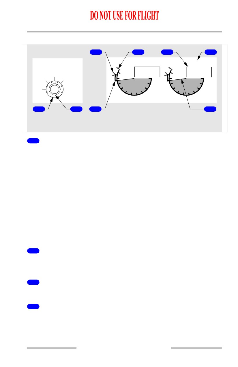
1
N1 SET Outer Knob
AUTO -
• both reference N1 bugs set by FMC based on N1 limit page and takeoff
reference page
• displays reference N1 bugs at active N1 limit for A/T.
BOTH -
• both reference N1 bugs and readouts manually set by turning N1 SET
inner knob
• has no effect on A/T operation.
1 or 2 -
• respective N1 reference bug and readout manually set by turning N1 SET
inner knob
• has no effect on A/T operation.
2
N1 SET Inner Knob (spring-loaded to center)
Rotate - positions reference N1 bug(s) and readouts when N1 SET outer knob is
set to BOTH, 1, or 2.
3
Reference N1 Bugs
Displayed (green) - with N1 SET outer knob in AUTO, 1, 2 or BOTH position.
4
N1 Redlines
Displayed (red) - N1% RPM operating limit
7.10.3
Engines, APU -
Side by Side - Displays
Boeing 737 Operations Manual
5
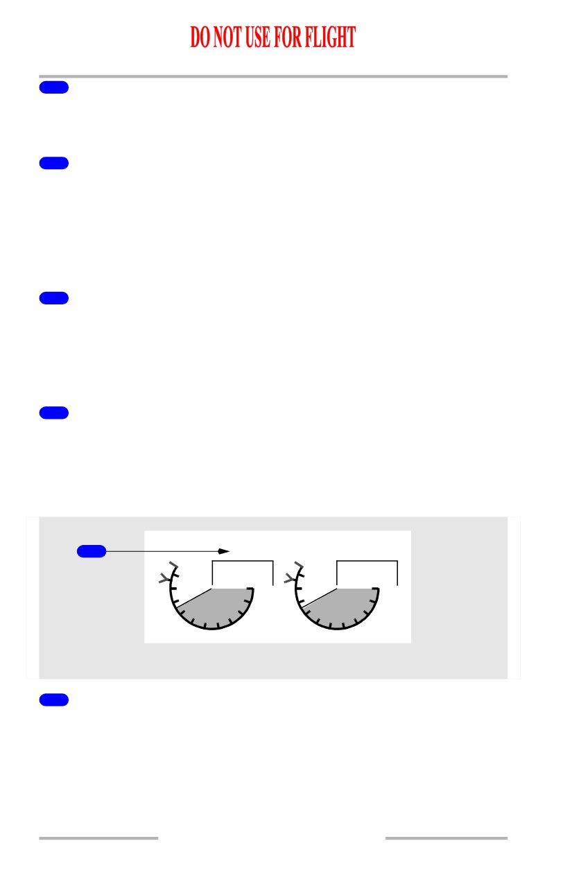
N1 Command Sectors
Displayed
(white)
- momentary difference between actual N1 and value
commanded by thrust lever position.
6
N1 RPM Readouts (digital)
Displayed (white) - normal operating range.
Displayed (red) -
• operating limit exceeded
• on ground after engine shutdown, red box indicates an inflight
exceedance has occurred.
7
Reference N1 Readouts
Displayed (green) - manually set N1% RPM:
• set with N1 SET inner knob when N1 SET is in BOTH, 1, or 2 position
• blank when N1 SET outer knob in AUTO position
•
- - - - when N1 SET outer knob in Auto and FMC source invalid.
8
N1 RPM Indications
Displays N1% RPM:
• displayed (white) - normal operating range
• displayed (red) - operating limit exceeded.
Thrust Reverser Indications
1
REV
REV
75.3
75.3
10
10
0
0
8
8
2
2
6
4
6
4
N1
UPPER DISPLAY UNIT
1
Thrust Reverser (REV) Indications
Displayed (amber) - thrust reverser is moved from stowed position.
Displayed (green) - thrust reverser is deployed.
7.10.4

Engines, APU -
Side by Side - Displays
Boeing 737 Operations Manual
Thermal Anti-Ice Indication
1
TAI
TAI
87.7
87.7
10
10
0
0
8
8
2
2
6
4
6
4
N1
UPPER DISPLAY UNIT
1
Thermal Anti-Ice (TAI) Indications
Displayed (green) - cowl anti-ice valve(s) open.
Displayed (amber) - cowl anti-ice valve is not in position indicated by related
engine anti-ice switch.
7.10.5
Engines, APU -
Side by Side - Displays
Boeing 737 Operations Manual
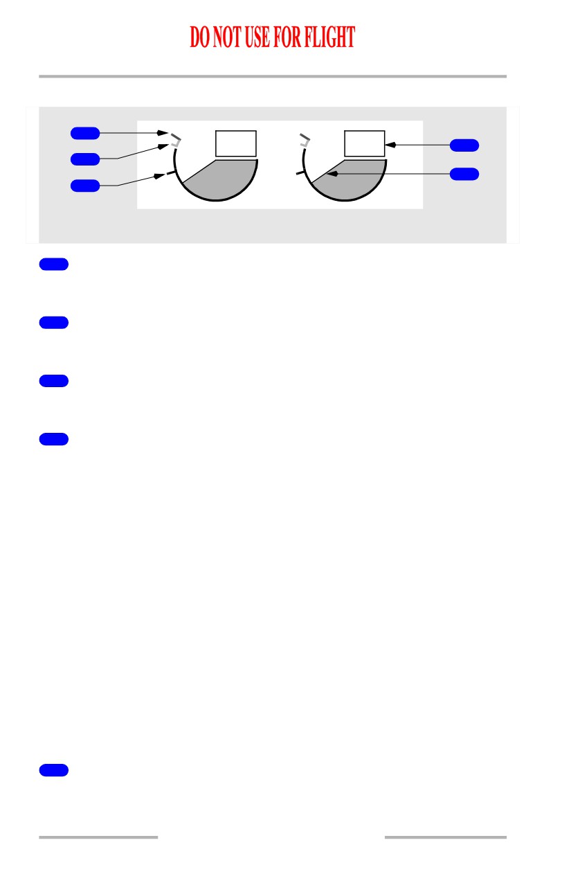
EGT Indications
1
663
663
4
2
5
3
EGT
UPPER DISPLAY UNIT
1
Exhaust Gas Temperature (EGT) Redlines
Displayed (red) - maximum takeoff EGT limit.
2
Exhaust Gas Temperature (EGT) Amber Bands
Displayed (amber) - lower end of band displays maximum continuous EGT limit.
3
Exhaust Gas Temperature (EGT) Start Limit Lines
Displayed (red) - N2 less than 50%.
4
Exhaust Gas Temperature (EGT) Readouts (digital)
Displayed (white) - normal operating range (degrees C)
[Option - Color change inhibit 5 minutes]
Displayed (amber) - maximum continuous limit exceeded; color change inhibited
for up to 5 minutes during takeoff or go-around
[Option - Color change inhibit 10 minutes]
Displayed (amber) - maximum continuous limit exceeded
• color change inhibited for up to 5 minutes during takeoff or go-around
(normal operation)
• color change inhibited for up to 10 minutes during takeoff or go-around
(when an engine out condition occurs within the first 5 minutes of the
inhibit)
Displayed (red) - maximum takeoff limit or start limit exceeded
On ground, after engine shutdown, red box indicates an exceedance has occurred
EEC senses conditions that may lead to hot start during ground starts (blinking
white box).
5
Exhaust Gas Temperature (EGT) Indications
Displayed (white) - normal operating range.
7.10.6
Engines, APU -
Side by Side - Displays
Boeing 737 Operations Manual
[Option - Color change inhibit 5 minutes]
Displayed (amber) - maximum continuous limit exceeded; color change inhibited
for up to 5 minutes during takeoff or go-around
[Option - Color change inhibit 10 minutes]
Displayed (amber) - maximum continuous limit exceeded
• color change inhibited for up to 5 minutes during takeoff or go-around
(normal operation)
• color change inhibited for up to 10 minutes during takeoff or go-around
(when an engine out condition occurs within the first 5 minutes of the
inhibit)
Displayed (red) - maximum takeoff limit or start limit exceeded.
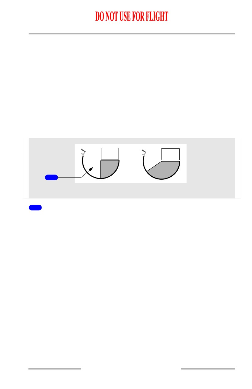
Engine Fail Alert
467
663
ENG
FAIL
1
EGT
UPPER DISPLAY UNIT
1
Engine Fail (ENG FAIL) Alert
Displayed (amber) -
• engine N2 below sustainable idle (less than 50%); and
• engine start lever in IDLE position.
Alert remains until -
• engine N2 above sustainable idle (50% or greater); or
• start lever moved to CUTOFF; or
• engine fire warning switch pulled.
7.10.7
Engines, APU -
Side by Side - Displays
Boeing 737 Operations Manual
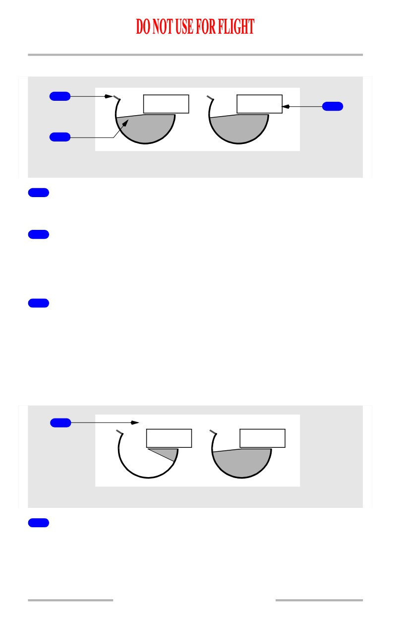
N2 Indications
1
87.7
87.7
3
2
N2
UPPER DISPLAY UNIT
1
N2 Redlines
Displayed (red) - N2 % RPM operating limit.
2
N2 RPM Indications
Displays N2 % RPM
• displayed (white) - normal operating range
• displayed (red) - operating limit exceeded.
3
N2 Readouts (digital)
Displayed (white) - normal operating range.
Displayed (red) -
• operating limit exceeded
• on ground, after engine shutdown, red box indicates an inflight
exceedance has occurred.
Crossbleed Start Indication
1
X-BLD START
12.7
87.6
N2
UPPER DISPLAY UNIT
1
Crossbleed (X-BLD) START Indication
Displayed (magenta) - crossbleed air recommended for inflight start.
Displayed when airspeed is less than required for a windmilling start.
7.10.8
Engines, APU -
Side by Side - Displays
Boeing 737 Operations Manual
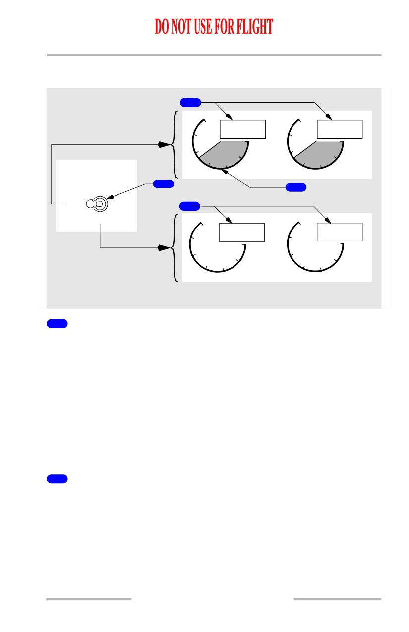
Fuel Flow/Fuel Used Indications
[Option - lbs]
2
12
12
7.27
7.27
0
0
8
8
FF/FU
4
4
LB X 1000
FUEL FLOW
RESET
1
3
RATE
4
USED
12
12
12.36
12.36
0
0
8
8
4
FF/FU
4
LB X 1000
CENTER
FORWARD PANEL
UPPER DISPLAY UNIT
1
FUEL FLOW Switch (spring-loaded to RATE)
RATE - displays fuel flow to engine.
USED -
• pointer and shading are removed
• displays fuel used since last reset
• after 10 seconds, display automatically reverts to fuel flow.
RESET -
• pointer and shading are removed
• resets fuel used to zero
• displays fuel used momentarily, decreases to zero, then displays fuel flow.
2
Fuel Flow (FF) Readout (digital)
[Option - lbs]
Displayed (white) - fuel flow to engine with FUEL FLOW switch in RATE
position (pounds per hour x 1000).
7.10.9
Engines, APU -
Side by Side - Displays
Boeing 737 Operations Manual
3
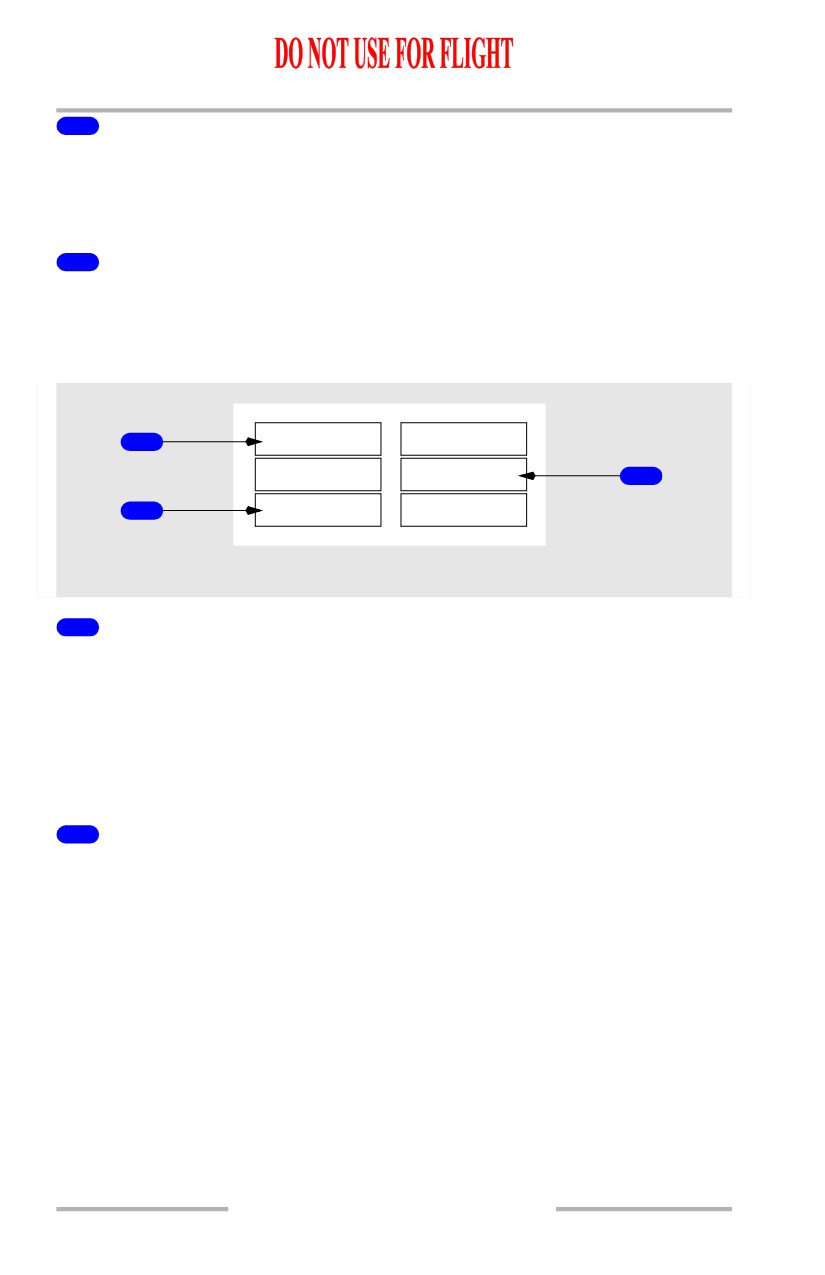
Fuel Flow (FF) Dial/ Index Markers & Digits (white)
[Option - lbs]
Displayed (white) - fuel flow to engine with FUEL FLOW switch in RATE
position (pounds per hour x 1000).
4
Fuel Used (FU) Readout (digital)
Illuminated (white) - displayed when FUEL FLOW switch moved to USED or
RESET.
Crew Alerts
START VALVE
START VALVE
1
OPEN
OPEN
OIL FILTER
OIL FILTER
BYPASS
BYPASS
3
LOW OIL
LOW OIL
2
PRESSURE
PRESSURE
UPPER DISPLAY UNIT
1
START VALVE OPEN Alert
Illuminated (amber) -
• steady - respective engine start valve open and air is supplied to starter
• blinking - uncommanded opening of start valve. Alert is displayed and
solid amber boxes are displayed in unannunciated positions for that
engine. All three boxes blink for ten seconds, then alert remains on steady
and solid amber boxes are removed (see Note).
2
LOW OIL PRESSURE Alert
Illuminated (amber) -
• steady - oil pressure at or below red line
• blinking - with a condition of low oil pressure. Alert is displayed and
solid amber boxes are displayed in unannunciated positions for that
engine. All three boxes blink for ten seconds, then alert remains on steady
and solid amber boxes are removed (see Note).
7.10.10
Engines, APU -
Side by Side - Displays
Boeing 737 Operations Manual
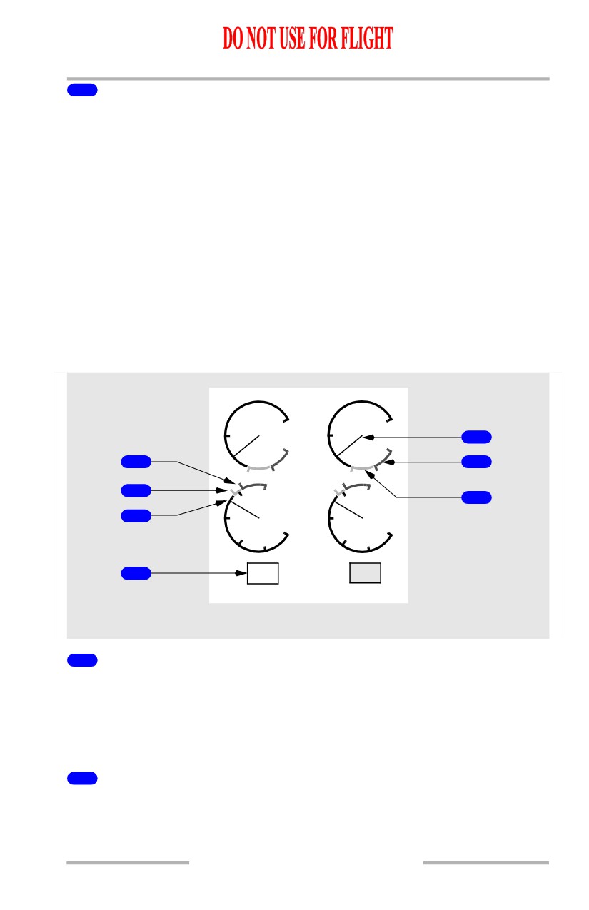
3
OIL FILTER BYPASS Alert
Illuminated (amber) -
• steady - indicates an impending bypass of scavenge oil filter
• blinking - with an impending bypass. Alert is displayed and solid amber
boxes are displayed in unannunciated positions for that engine. All three
boxes blink for ten seconds, then alert remains on steady and solid amber
boxes are removed (see Note).
Note: Blinking is inhibited:
• during takeoff from 80 knots to 400 feet RA, or 30 seconds after reaching
80 knots, whichever occurs first
• during landing below 200 feet RA until 30 seconds after touchdown
• during periods when blinking is inhibited, alerts illuminate steady.
Engine Oil Indications
[Option - Low oil quantity reverse video]
OIL QTY
100
100
50
50
1
0
0
4
2
OIL P
5
200
200
3
6
100
100
0
0
OIL T
7
LO
95
18
OIL Q %
UPPER DISPLAY UNIT
1
Oil Pressure (OIL P) Indication
Displays engine oil pressure (psi)
• displayed (white) - normal operating range
• displayed (amber) - caution range
• displayed (red) - operating limit reached.
2
Low Oil Pressure (OIL P) Redline
Displayed (red) - oil pressure operating limit.
7.10.11
Engines, APU -
Side by Side - Displays
Boeing 737 Operations Manual
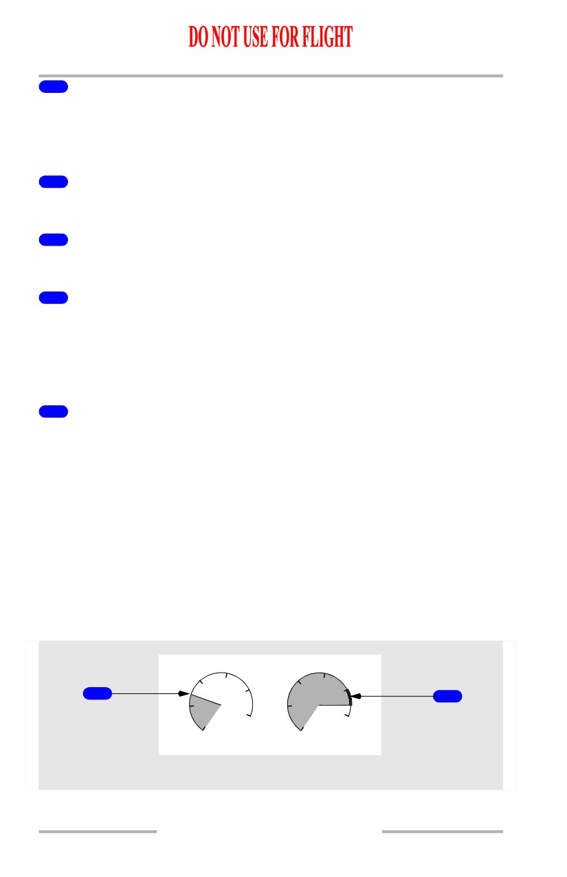
3
Low Oil Pressure (OIL P) Amber Band
Displayed (amber) - low oil pressure caution range beginning at red line:
• variable depending on N2% RPM above 65% N2
• amber band not displayed below 65% N2.
4
High Oil Temperature (OIL T) Redline
Displayed (red) - oil temperature operating limit.
5
High Oil Temperature (OIL T) Amber Band
Displayed (amber) - oil temperature caution range.
6
Oil Temperature (OIL T) Indication
Displays oil temperature (degrees C):
• displayed (white) - normal operating range
• displayed (amber) - caution range reached
• displayed (red) - operating limit reached.
7
Oil Quantity (OIL Q)% Readout
Displays usable oil quantity as a percentage of full quantity.
[Option - Low oil quantity reverse video]
Video is reversed and LO (white) displayed for low oil quantity.
Note: Indicated oil quantity may decrease significantly during engine start,
takeoff and climb out. If this occurs, engine operation is not impacted and
the correct oil quantity should be indicated during level flight.
Note: An oil quantity indication as low as zero is normal if windmilling N2 RPM
is below approximately 8%.
Engine Vibration Indications
[Option - High vibration alert]
3
3
2
2
1
4
4
2
1
1
5
5
0
0
VIB
UPPER DISPLAY UNIT
7.10.12
Engines, APU -
Side by Side - Displays
Boeing 737 Operations Manual
1
Vibration (VIB) Pointer
Displayed (white) - engine vibration level.
2
High Engine Vibration Indication
[Option - High vibration alert]
Displayed (white)
When engine vibration level is greater than four units, the portion of the dial arc
between 4 units and the pointer, becomes bold.
7.10.13
Engines, APU -
Side by Side - Displays
Boeing 737 Operations Manual
Intentionally
Blank
7.10.14
Boeing 737 Operations Manual
Engines, APU
Chapter 7
Over/Under - Displays
Section 11
Primary Engine Indications
[Option - Over/Under display, kgs, fuel flow displayed full time]
TAT
- 12 C
R-TO
+42C
ENG 1
ENG 2
START VALVE
START VALVE
96.0
96.0
OPEN
OPEN
TAI
TAI
OIL FILTER
OIL FILTER
10
87.7
10
87.7
BYPASS
BYPASS
0
0
LOW OIL
LOW OIL
8
8
PRESSURE
PRESSURE
2
2
6
4
6
4
1
N
1
663
663
EGT
3
3.80
FF
3.80
CTR
7600
FUEL
2
KG
1
2
3 900
3 900
UPPER DISPLAY UNIT
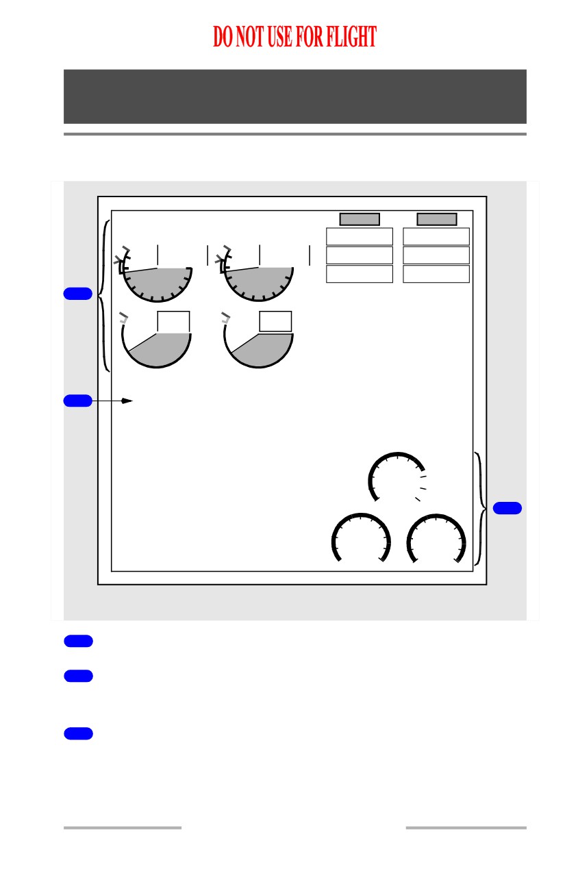
1
Primary Engine Indications
2
Fuel Quantity Indications
Refer to Chapter 12, Fuel
3
Fuel Flow Indications
[Option - Fuel flow displayed full time]
7.11.1
Engines, APU -
Over/Under - Displays
Boeing 737 Operations Manual
Total Air Temperature, Thrust Mode Display, Selected
Temperature and Autothrottle Limit
1
C
3
TAT 12
R-TO
+42 C
2
UPPER DISPLAY UNIT
TAT 12
C
A/T LIM
+
42
C
4
UPPER DISPLAY UNIT
1
Total Air Temperature (TAT) Indication
Displayed (label - cyan, temp - white) - total air temperature (degrees C).
2
Thrust Mode Display
Displayed (green) - the active N1 limit reference mode.
With N1 manual select knob on engine display control panel in AUTO, active N1
limit is displayed by reference N1 bugs.
Active N1 limit is normally calculated by FMC.
Thrust mode display annunciations are:
• R-TO - reduced takeoff
• R-CLB - reduced climb
• TO - takeoff
[Option]
• TO B - takeoff bump thrust
• CLB - climb
• CRZ - cruise
• G/A - go-around
• CON - continuous
•
- - - - FMC not computing thrust limit.
Note: R-TO does not indicate the type of reduced takeoff. The N1 limit may be
reduced due to the entry of an assumed temperature, a takeoff thrust derate
or a combination of both assumed temperature and takeoff thrust derate.
7.11.2
Engines, APU -
Over/Under - Displays
Boeing 737 Operations Manual
3
Selected Temperature
Displayed (green) - selected assumed temperature (degrees C) for reduced thrust
takeoff N1.
Repeats data selected on TAKEOFF REF page.
4
Autothrottle Limit (A/T LIM) Indication
Illuminated (white) - The FMC is not providing the A/T system with N1 limit
values. The A/T is using a degraded N1 thrust limit from the related EEC.
Replaces thrust mode display annunciation when illuminated.
N1 Indications
3
4
6
7
96.0
96.0
N1 SET
AUTO
10
87.7
10
87.7
1
BOTH
0
0
8
8
2
2
2
6
4
6
4
N
1
1
2
5
8
CENTER
FORWARD PANEL
UPPER DISPLAY UNIT
1
N1 SET Outer Knob
AUTO -
• both reference N1 bugs set by FMC based on N1 limit page and takeoff
reference page
• displays reference N1 bugs at active N1 limit for A/T.
BOTH -
• both reference N1 bugs and readouts manually set by turning N1 SET
inner knob
• has no effect on A/T operation.
1 or 2 -
• respective N1 reference bug and readout manually set by turning N1 SET
inner knob
• has no effect on A/T operation.
7.11.3