Boeing 737 - 600/700/800/900. Operations Manual (1997 year) - page 34
Electrical -
System Description
Boeing 737 Operations Manual
Automatic Load Shedding (Engine Generators)
[Option - CAB/UTIL Power Switch]
For single generator operation, the system is designed to shed electrical load
incrementally based on actual load sensing. The galleys and main bus on transfer
bus 2 are shed first; if an overload is still sensed, the galleys and main bus on
transfer bus 1 are shed; if overload still exists, the IFE buses are shed. When
configuration changes to more source capacity
(two generator operation),
automatic load restoration of the main busses, galley busses and IFE buses occurs;
manual restoration of galley and main bus power can be attempted by moving the
CAB/UTIL Power Switch to OFF, then back ON.
APU Automatic Load Shedding
[Option - CAB/UTIL Power Switch]
In flight, if the APU is the only source of electrical power, all galley busses and
main buses are automatically shed. If electrical load still exceeds design limits,
both IFE busses are also automatically shed. On the ground, the APU attempts to
carry a full electrical load. If an overload condition is sensed, the APU sheds
galley busses and main busses until the load is within limits. Manual restoration
of galley and main bus power can be attempted by moving the CAB/UTIL Power
Switch to OFF, then back ON.
6.20.6
Electrical -
System Description
Boeing 737 Operations Manual
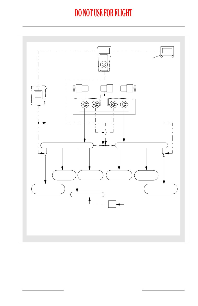
AC Power Schematic
GRD POWER
AVAILABLE
GRD
PWR
OFF
ON
GEN
GEN
GEN
GEN
DRIVE
1
GEN
APU
2
DRIVE
GROUND
OFF
OFF
SERVICE
ON
ON
GEN 1
APU GEN
GEN 2
APU
to GND
from GND
SVC BUS 2
SVC SWITCH
AC TRANSFER BUS 1
AC TRANSFER BUS 2
BTB1
BTB2
GND
GND
SERVICE
SERVICE
RELAY
RELAY
GALLEY
115V AC
115V AC
GALLEY
BUS C & D
MAIN BUS 1
MAIN BUS 2
BUS A & B
115V AC GND
115V AC GND
SERVICE BUS 1
SERVICE BUS 2
AC STANDBY BUS
INV
from BAT/BAT CHG
Airplane Configuration:
Battery Switch
- ON
Standby Power Switch - AUTO
Bus Transfer Switch - AUTO
ENGINE GENERATOR CONNECTED TO RELATED BUS
6.20.7
Electrical -
System Description
Boeing 737 Operations Manual
Electrical Power Controls and Monitoring
Generator Drive
The IDGs contain the generator and drive in a common housing, and are lubricated
and cooled by a self-contained oil system. An integral electro-mechanical
disconnect device provides for complete mechanical isolation of the IDG.
The generator drive (DRIVE) amber caution light is illuminated when low oil is
sensed in the IDG. IDG low oil pressure is caused by one of the following:
• IDG failure
• engine shutdown
• IDG automatic disconnect due to high oil temperature
• IDG disconnected through generator drive DISCONNECT switch.
A generator drive disconnect switch is installed. This switch disconnects the
generator from the engine in the event of a generator drive malfunction.
Reactivation of the generator may be accomplished only on the ground by
maintenance personnel.
AC Voltmeter, Ammeter and Frequency Meter
AC voltage and frequency may be read on the AC voltmeter and frequency meter
for standby power, ground power, generator No. 1, APU generator, generator No.
2 and the static inverter. Frequency is indicated only when the generator is
electrically excited. The voltage regulator automatically controls the generator
output voltage.
Current readings for the two engine IDGs and the APU generator may be read on
the AC ammeter.
The TEST position is used by maintenance and connects the voltage and
frequency meter to the power systems test module for selection of additional
reading points.
Normal indications are:
• AC voltmeter - 115 +/- 5volts
• Frequency meter - 400 CPS +/- 10 CPS.
Note: Normal AC voltmeter indication for the APU generator with the AC busses
loaded: 110 - 125 volts.
DC Voltmeter and Ammeter
DC voltage and amperage may be read on the DC voltmeter and ammeter for the
battery and each of the three TRs. The standby power and battery bus displays
only DC voltage.
6.20.8
Electrical -
System Description
Boeing 737 Operations Manual
Normal indication is 26 +/- 4 volts. During primary charge cycle operation battery
voltage can be as high as 30 +/- 3 volts.
The TEST position is used by maintenance.
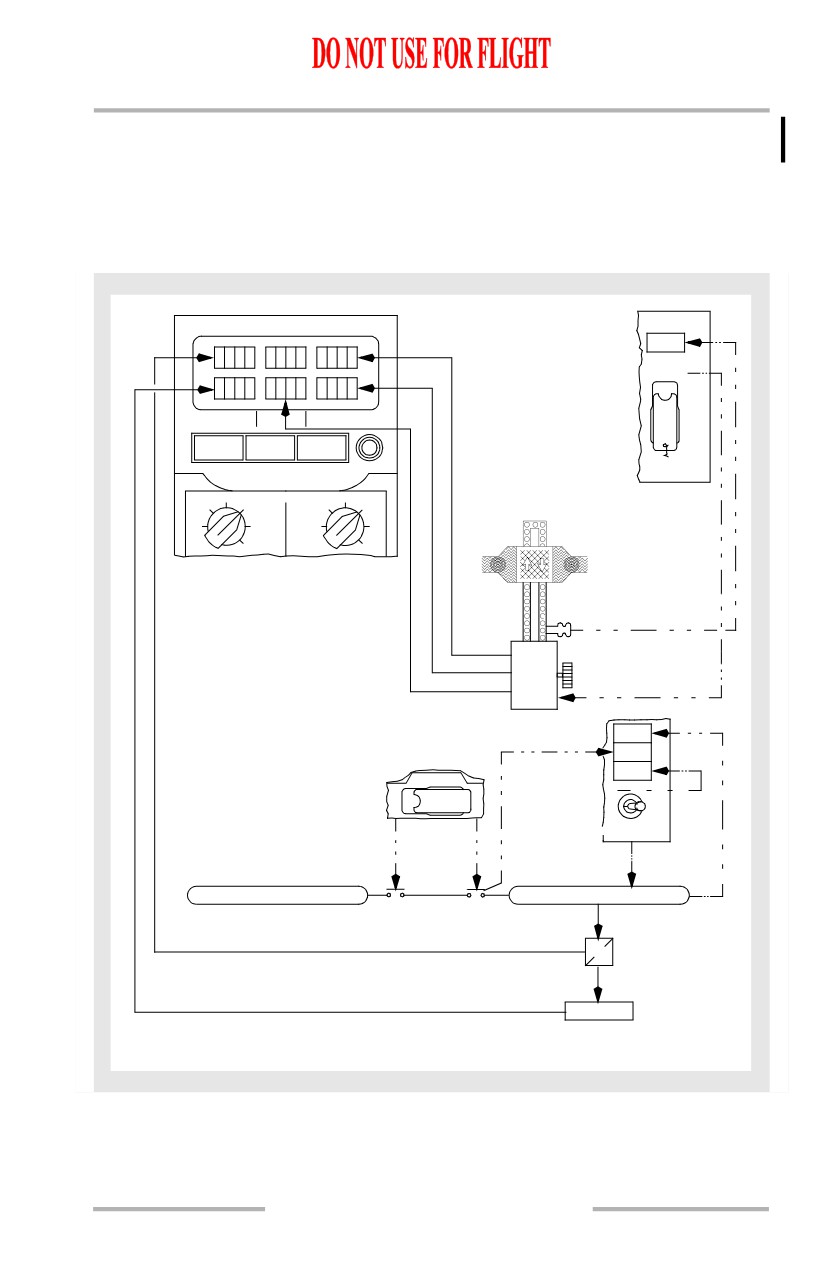
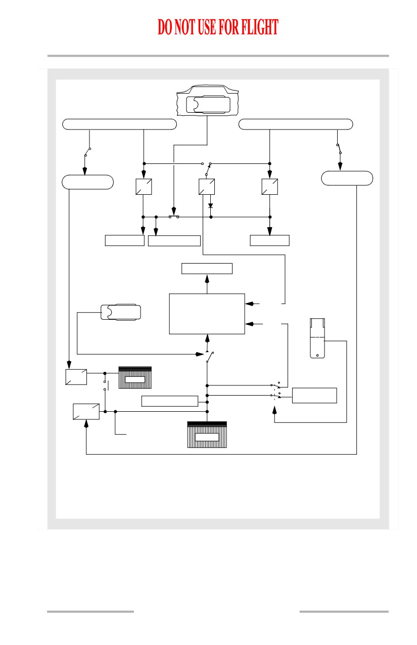
Electrical Power Controls and Monitoring Schematic
[Option - Single battery]
DC AMPS
CPS FREQ
2
DRIVE
DISCONNECT
DC VOLTS AC AMPS AC VOLTS
BAT
TR UNIT
ELEC
DISCHARGE
MAINT
TR 1
APU GEN
BAT
TR 2
GEN 1
GEN 2
BAT
TR 3
GRD
INV
BUS
PWR
STBY
STBY
TEST
PWR
TEST
PWR
FAN
AIR
IDG2
TRANSFER
BUS OFF
SOURCE
OFF
GEN OFF
BUS
BUS TRANSFER
O
A
OFF
F
U
F
T
O
ON
FROM
GEN 2
GENERATOR 1
AC TRANSFER BUS 1
AC TRANSFER BUS 2
TR2
DC BUS 2
CONDITION: ENGINE DRIVEN GENERATORS ON AC BUSSES
6.20.9
Electrical -
System Description
Boeing 737 Operations Manual
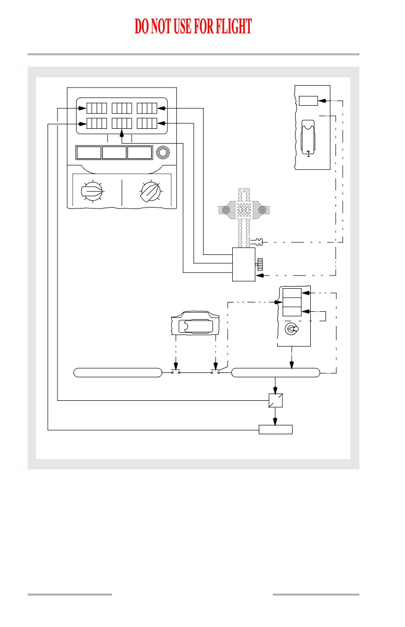
[Option - Dual battery]
DC AMPS
CPS FREQ
2
DRIVE
DISCONNECT
DC VOLTS AC AMPS AC VOLTS
BAT
TR UNIT
ELEC
DISCHARGE
MAINT
AUX BAT
APU GEN
BAT
TR 1
GEN 1
GEN 2
BAT
TR 2
GRD
INV
BUS
PWR
STBY
STBY
TEST
PWR
TR 3
PWR
TEST
FAN
AIR
IDG2
TRANSFER
BUS OFF
SOURCE
OFF
GEN OFF
BUS
BUS TRANSFER
O
A
OFF
F
U
F
T
O
ON
FROM
GEN 2
GENERATOR 1
AC TRANSFER BUS 1
AC TRANSFER BUS 2
TR2
DC BUS 2
CONDITION: ENGINE DRIVEN GENERATORS ON AC BUSSES
6.20.10
Electrical -
System Description
Boeing 737 Operations Manual
DC Power System
28 volt DC power is supplied by three TR units, which are energized from the AC
transfer busses. The battery provides DC power to loads required to be operative
when no other source is available.
On the ground, an amber ELEC light comes on to indicate that a fault exists in DC
power system or standby power system. The ELEC light is inhibited in flight.
Transformer Rectifier Units
The TRs convert 115 volt AC to 28 volt DC, and are identified as TR1, TR2, and
TR3.
TR1 receives AC power from transfer bus 1. TR2 receives AC power from
transfer bus 2. TR3 normally receives AC power from transfer bus 2 and has a
backup source of AC power from transfer bus 1. Any two TRs are capable of
supplying the total connected load.
Under normal conditions, DC bus 1, DC bus 2, and the DC standby bus are
connected via the cross bus tie relay. In this condition, TR1 and TR2 are each
powering DC bus 1, DC bus 2, and the DC standby bus. TR3 powers the battery
bus and serves as a backup power source for TR1 and TR2.
The cross bus tie relay automatically opens, isolating DC bus 1 from DC bus 2,
under the following conditions:
• At glide slope capture during a flight director or autopilot ILS approach.
This isolates the DC busses during approach to prevent a single failure
from affecting both navigation receivers and flight control computers
• Bus transfer switch positioned to OFF.
In-flight, an amber TR UNIT light illuminates if TR1, or TR2 and TR3 has failed.
On the ground, any TR fault causes the light to illuminate.
Battery Power
Single Battery
[Option]
A 24 volt nickel-cadmium battery is located in the electronics compartment. The
battery can supply part of the DC system. Battery charging is automatically
controlled. A fully charged battery has sufficient capacity to provide standby
power for a minimum of 30 minutes. Battery voltage range is 22-30 volts.
DC busses powered from the battery following a loss of both generators are:
• battery bus
• DC standby bus
6.20.11
Electrical -
System Description
Boeing 737 Operations Manual
• hot battery bus
• switched hot battery bus.
The switched hot battery bus is powered whenever the battery switch is ON.
The hot battery bus is always connected to the battery. There is no switch in this
circuit. The battery must be above minimum voltage to operate units supplied by
this bus. An amber BAT DISCHARGE light comes on when excessive battery
discharge is detected.
Dual Battery
[Option]
Two 24 volt nickel-cadmium batteries, main and auxiliary, are located in the
electronics compartment. The batteries can supply part of the DC system. The
auxiliary battery operates in parallel with the main battery when the battery is
powering the standby system. At all other times, the auxiliary battery is isolated
from the power distribution system. Battery charging is automatically controlled.
Two fully charged batteries have sufficient capacity to provide standby power for
a minimum of 60 minutes. Battery voltage range is 22-30 volts.
DC busses powered from the battery following a loss of both generators are:
• battery bus
• DC standby bus
• hot battery bus
• switched hot battery bus.
The switched hot battery bus is powered whenever the battery switch is ON.
The hot battery bus is always connected to the battery. There is no switch in this
circuit. The battery must be above minimum voltage to operate units supplied by
this bus. An amber BAT DISCHARGE light comes on when excessive battery
discharge is detected.
Battery Charger Transformer/Rectifier
Single Battery
[Option]
The purpose of the battery charger is to restore and maintain the battery at full
electrical power. The battery charger is powered through AC ground service bus 2.
The battery charger provides a voltage output tailored to maximize the battery
charge. Following completion of the primary charge cycle, the battery charger
reverts to a constant voltage TR mode. In the TR mode, it powers loads connected
to the hot battery bus and the switched hot battery bus. The battery charger TR also
powers the battery bus if TR3 fails. With loss of AC transfer bus 1 or the source
of power to DC bus 1, the AC and DC standby busses are powered by the
battery/battery charger.
6.20.12
Electrical -
System Description
Boeing 737 Operations Manual
Dual Battery
[Option]
The purpose of the battery chargers is to restore and maintain the batteries at full
electrical power. The main battery charger is powered through AC ground service
bus 2. The auxiliary battery charger is powered through AC ground service bus 1.
The battery chargers provide a voltage output tailored to maximize the battery
charge. Following completion of the primary charge cycle, the main battery
charger reverts to a constant voltage TR mode. In the TR mode, it powers loads
connected to the hot battery bus and the switched hot battery bus. The main battery
charger TR also powers the battery bus if TR3 fails. With loss of AC transfer bus
1 or the source of power to DC bus 1, the AC and DC standby busses are powered
by the main and auxiliary battery/battery chargers.
The auxiliary battery charger and battery are isolated from the power distribution
system under normal operation. When the main battery is powering the standby
system, the auxiliary battery is connected to operate in parallel with the main
battery.
6.20.13
Electrical -
System Description
Boeing 737 Operations Manual
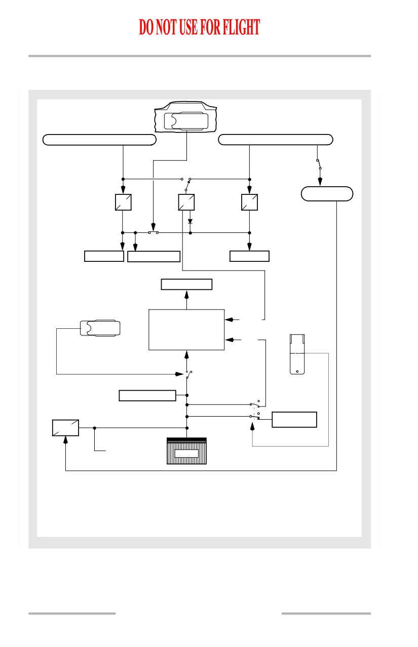
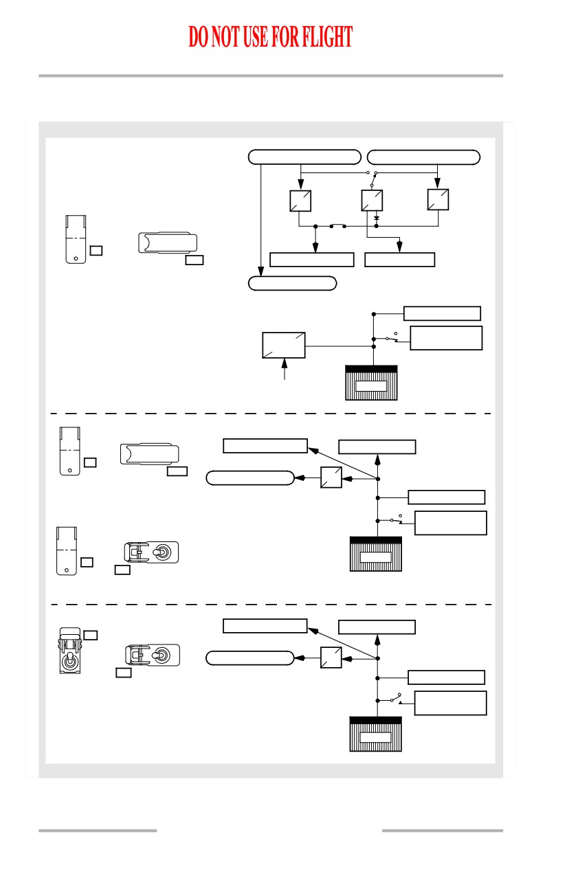
DC Power System Schematic
[Option - Single battery]
BUS TRANSFER
A
O
U
F
T
F
O
AC TRANSFER BUS 1
AC TRANSFER BUS 2
115V AC GND
SERVICE BUS 2
TR1
TR3
TR2
CROSS BUS
TIE RELAY
DC BUS 1
DC STANDBY BUS
DC BUS 2
BATTERY BUS
NORMAL
STANDBY POWER
CONTROL UNIT
STBY
OFF
BAT OFF AUTO
STANDBY POWER SWITCH
ON
ALTERNATE
BATTERY
SWITCH
HOT BATTERY BUS
SWITCHED
BATT
HOT BAT BUS
CHGR
TO APU STARTER
BAT
Airplane Configuration - In Flight
Battery Switch
- ON
Standby Power Switch - AUTO
Bus Transfer Switch
- AUTO
ENGINE GENERATOR CONNECTED
6.20.14
Electrical -
System Description
Boeing 737 Operations Manual
[Option - Dual battery]
BUS TRANSFER
O
A
F
U
F
T
O
AC TRANSFER BUS 1
AC TRANSFER BUS 2
115V AC GND
115V AC GND
SERVICE BUS 2
SERVICE BUS 1
TR1
TR3
TR2
CROSS BUS
TIE RELAY
DC BUS 1
DC STANDBY BUS
DC BUS 2
BATTERY BUS
NORMAL
STANDBY POWER
CONTROL UNIT
STBY
OFF
BAT OFF AUTO
STANDBY POWER SWITCH
ON
ALTERNATE
BATTERY
SWITCH
AUX
BATT
CHGR
AUX BAT
SWITCHED
HOT BATTERY BUS
HOT BAT BUS
BATT
CHGR
TO APU STARTER
BAT
Airplane Configuration - In Flight
Battery Switch
- ON
Standby Power Switch - AUTO
Bus Transfer Switch
- AUTO
ENGINE GENERATOR CONNECTED TO RELATED BUS
6.20.15
Electrical -
System Description
Boeing 737 Operations Manual
Standby Power System
Normal Operation
The standby system provides 115V AC and 24V DC power to essential systems
in the event of loss of all engine or APU-driven AC power. The standby power
system consists of:
• static inverter
• AC standby bus
• DC standby bus
• battery bus
• hot battery bus
• switched hot battery bus
• main battery
[Option - Dual battery]
• auxiliary battery.
During normal operation the guarded standby power switch is in AUTO and the
battery switch is ON. This configuration provides alternate power sources in case
of partial power loss as well as complete transfer to battery power if all normal
power is lost. Under normal conditions the AC standby bus is powered from AC
transfer bus 1. The DC standby bus is powered by TR1, TR2, and TR3; the battery
bus is powered by TR3; the hot battery bus and switched hot battery bus are
powered by the battery/battery charger.
Alternate Operation
Single Battery
[Option]
The alternate power source for standby power is the battery. With the standby
power switch in the AUTO position, the loss of all engine or APU electrical power
causes the battery to power the standby loads, both in the air and on the ground.
The AC standby bus is powered from the battery via the static inverter. The DC
standby bus, battery bus, hot battery bus, and switched hot battery bus are powered
directly from the battery.
The standby power switch provides for automatic or manual control of power to
the standby buses.
In the AUTO position, automatic switching from normal to alternate power occurs
if power from either AC transfer bus 1 or DC bus 1 is lost.
6.20.16
Electrical -
System Description
Boeing 737 Operations Manual
Positioning the switch to BAT overrides automatic switching and places the AC
standby bus, DC standby bus, and battery bus on battery power. The battery switch
may be ON or OFF. If the battery switch is OFF, the switched hot battery bus is
not powered.
Positioning the standby power switch to OFF de-energizes both the AC standby
bus and the DC standby bus and illuminates the STANDBY PWR OFF light.
Dual Battery
[Option]
The alternate power sources for standby power are the main battery and auxiliary
battery. With the standby power switch in the AUTO position, the loss of all
engine or APU electrical power causes the batteries to power the standby loads,
both in the air and on the ground. The AC standby bus is powered from the
batteries via the static inverter. The DC standby bus, battery bus, hot battery bus,
and switched hot battery bus are powered directly from the batteries.
The standby power switch provides for automatic or manual control of power to
the standby buses.
In the AUTO position, automatic switching from normal to alternate power occurs
if power from either AC transfer bus 1 or DC bus 1 is lost.
Positioning the switch to BAT overrides automatic switching and places the AC
standby bus, DC standby bus, and battery bus on battery power. The battery switch
may be ON or OFF. If the battery switch is OFF, the switched hot battery bus is
not powered.
Positioning the standby power switch to OFF de-energizes both the AC standby
bus and the DC standby bus and illuminates the STANDBY PWR OFF light.
Static Inverter
The static inverter converts 24 volt DC power from the battery to 115V AC power
to supply the AC standby bus during the loss of normal electrical power. The
power supply to the inverter is controlled by the standby power switch and the
battery switch on the overhead panel.
6.20.17
Electrical -
System Description
Boeing 737 Operations Manual
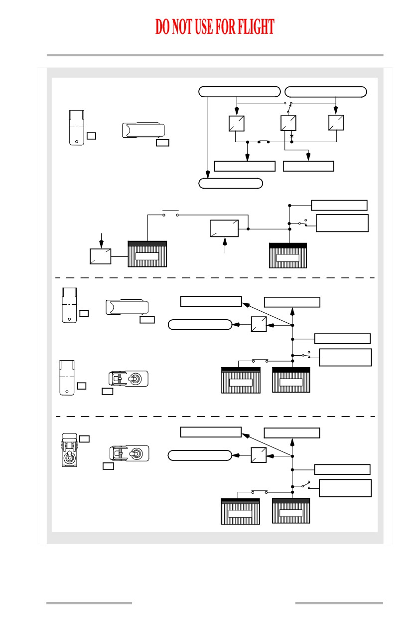
Standby Power System Schematic
[Option - Single battery]
TRANSFER BUS NO. 1
TRANSFER BUS NO. 2
TR1
TR3
TR2
OFF
STANDBY POWER
BAT
ON
BAT
OFF AUTO
DC STANDBY BUS
BATTERY BUS
TRANSFER BUSSES POWERED
AC STANDBY BUS
(NORMAL CONFIGURATION)
HOT BAT BUS
SWITCHED
BATT
HOT BAT BUS
CHGR
FROM GROUND
BAT
SERVICE BUS #2
OFF
STANDBY POWER
BAT
DC STANDBY BUS
BATTERY BUS
ON
BAT
OFF AUTO
AC STANDBY BUS
INV
TRANSFER BUSSES NOT POWERED
HOT BAT BUS
OR
SWITCHED
OFF
STANDBY POWER
HOT BAT BUS
BAT
ON
BAT
BAT
OFF AUTO
TRANSFER BUSSES POWERED OR NOT POWERED
DC STANDBY BUS
BATTERY BUS
OFF
STANDBY POWER
BAT
AC STANDBY BUS
INV
ON
BAT
OFF AUTO
HOT BAT BUS
TRANSFER BUSSES POWERED
SWITCHED
OR NOT POWERED
HOT BAT BUS
BAT
6.20.18
Electrical -
System Description
Boeing 737 Operations Manual
[Option - Dual battery]
TRANSFER BUS NO. 1
TRANSFER BUS NO. 2
OFF
STANDBY POWER
TR1
TR3
TR2
BAT
ON
BAT
OFF AUTO
TRANSFER BUSSES POWERED
(NORMAL CONFIGURATION)
DC STANDBY BUS
BATTERY BUS
AC STANDBY BUS
HOT BAT BUS
SWITCHED
FROM GROUND
BATT
SERVICE BUS #1
HOT BAT BUS
CHGR
AUX
BATT
AUX BAT
BAT
CHGR
FROM GROUND
SERVICE BUS #2
OFF
STANDBY POWER
BAT
DC STANDBY BUS
BATTERY BUS
ON
BAT
OFF AUTO
AC STANDBY BUS
INV
TRANSFER BUSSES NOT POWERED
HOT BAT BUS
OR
SWITCHED
STANDBY POWER
HOT BAT BUS
OFF
BAT
AUX BAT
BAT
ON
BAT
OFF AUTO
TRANSFER BUSSES POWERED OR NOT POWERED
DC STANDBY BUS
BATTERY BUS
OFF
STANDBY POWER
BAT
AC STANDBY BUS
INV
ON
BAT
OFF AUTO
HOT BAT BUS
TRANSFER BUSSES POWERED
SWITCHED
OR NOT POWERED
HOT BAT BUS
AUX BAT
BAT
6.20.19
Electrical -
System Description
Boeing 737 Operations Manual
All Generators Inoperative
The following list identifies the significant equipment that operates when the main
battery and the auxiliary battery are the only source of electrical power.
Airplane General
• standby compass light
• white dome lights
• emergency instrument flood lights
• flight crew oxygen
• passenger oxygen
[Option]
• standby forward airstair interior/exterior operation
Air Systems
• A/C pack valves
• BLEED TRIP OFF lights
• manual pressurization control
• altitude warning horn
[737-600/700]
• PACK TRIP OFF lights
[737-800/900]
• PACK lights
Anti-Ice
[Option]
• Captain’s pitot probe heat
Communications
• flight interphone system
• passenger address system
• VHF No. 1
Electrical
• STANDBY POWER OFF light
Engines, APU
• upper display unit
N1, N2, fuel flow, EGT, fuel quantity, oil pressure, oil temperature, oil
quantity
• upper display unit
N1, N2, fuel flow, EGT, fuel quantity, oil pressure, oil temperature, oil
quantity, hydraulic pressure, hydraulic quantity
6.20.20
October 15, 2001
Electrical -
System Description
Boeing 737 Operations Manual
• thrust reversers
• starter valves
• right igniters
• APU operation (start attempts not recommended above 25,000 feet)
Fire Protection
• APU and engine fire extinguisher bottles
• APU and engine fire detection system
• Cargo fire extinguisher bottle
Flight Instruments
• Captain’s outboard display unit (compact EFIS or PFD format)
[Option]
• Captain’s outboard and inboard display units (EFIS/MAP or PFD/ND
format)
• clocks
• left EFIS control panel
Flight Management, Navigation
• FMC
• left CDU
• heading/track indications
• VHF NAV No. 1
• ILS No. 1
• left IRS
• left GPS
• marker beacon
[Option]
• ADF No. 1
[Option]
• IFF No. 1
[Option]
• transponder No. 1
[Option]
• DME No. 1
Fuel
• crossfeed valve
• engine fuel shutoff valves
• spar fuel shutoff valve
6.20.21
Electrical -
System Description
Boeing 737 Operations Manual
• FUEL VALVE CLOSED lights
• fuel quantity indicators
Hydraulic Power
• engine hydraulic shutoff valves
• standby rudder shutoff valves
Landing Gear
• inboard antiskid system
• ANTISKID INOP light
• parking brake
• air/ground system
Warnings
• stall warning system
• aural warnings
• master caution light recall
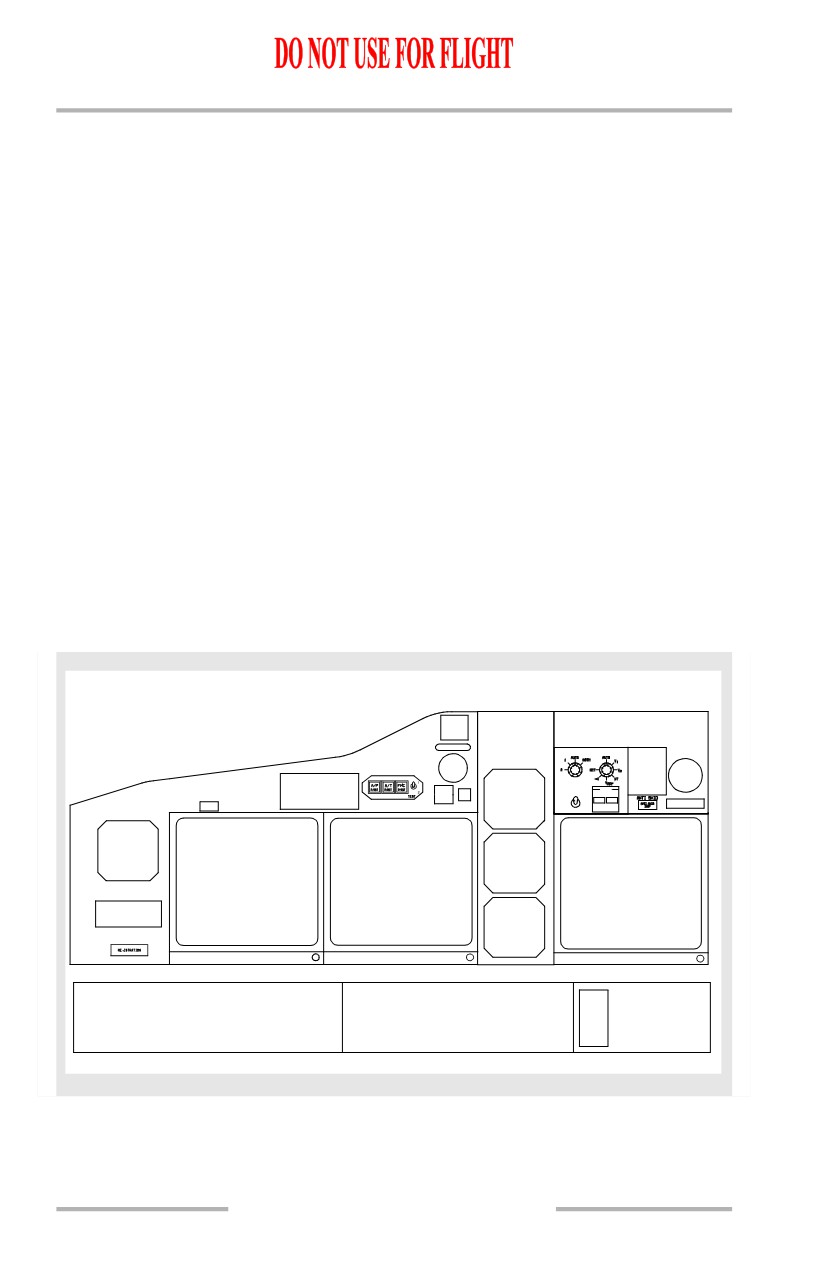
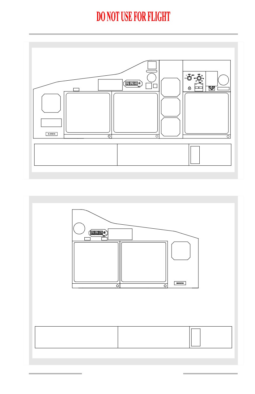
Basic Equipment Operating - Captain Instrument Panel
The standby power system utilizes the battery as a source of power to supply the
below depicted flight instruments. All of the Captain’s instruments that are
powered by standby power are integrally lighted on standby power
N1 SET
SPD REF
STBY
FUEL FLOW
RESET
MFD
RATE
ENG SYS
ATT
USED
CAPTAIN
CLOCK
OUTBOARD
STBY
SIDE BY SIDE
OR
DISPLAY
ALT/AS
COMPACT
OVER/UNDER
COMPACT EFIS
STBY
DISPLAY
OR PFD
RMI
This illustration shows the
Airplane Configuration - In Flight
Indicates
instruments which are usable
Battery Switch
- ON
Inoperative
with only the batteries and
Standby Power Switch
- AUTO
Instruments
standby busses powered.
6.20.22
Electrical -
System Description
Boeing 737 Operations Manual
[Option - Captain’s Outboard and Inboard Display Units on Standby Power]
N1 SET
SPD REF
STBY
FUEL FLOW
RESET
MFD
RATE
ENG SYS
ATT
USED
CAPTAIN
CAPTAIN
CLOCK
OUTBOARD
INBOARD
STBY
SIDE BY SIDE
DISPLAY
DISPLAY
OR
ALT/AS
COMPACT
EFIS
EFIS/MAP
OVER/UNDER
OR
OR
STBY
DISPLAY
PFD
ND
RMI
This illustration shows the
Airplane Configuration - In Flight
Indicates
instruments which are usable
Battery Switch
- ON
Inoperative
with only the batteries and
Standby Power Switch
- AUTO
Instruments
standby busses powered.
Basic Equipment Operating - First Officer Instrument Panel
CLOCK
FLIGHT DECK COMMUNICATION
FLIGHT DECK LIGHTS
Audio Selector Panels
Standby Instrument Floodlight
Flight Interphone
White Dome Light
Passenger Address System
Magnetic Compass Light
This illustration shows the
Airplane Configuration - In Flight
Indicates
instruments which are usable
Battery Switch
- ON
Inoperative
with only the batteries and
Standby Power Switch
- AUTO
Instruments
standby busses powered.
6.20.23
Electrical -
System Description
Boeing 737 Operations Manual
Intentionally
Blank
6.20.24
Boeing 737 Operations Manual
Engines, APU
Chapter 7
Table of Contents
Section 0
7.0 Engines, APU-Table of Contents
Side by Side - Displays
7.10.1
Primary and Secondary Engine Indications
7.10.1
Autothrottle Limit, Thrust Mode Display and Total
Air Temperature
7.10.2
N1 Indications
7.10.3
Thrust Reverser Indications
7.10.4
Thermal Anti-Ice Indication
7.10.5
EGT Indications
7.10.6
Engine Fail Alert
7.10.7
N2 Indications
7.10.8
Crossbleed Start Indication
7.10.8
Fuel Flow/Fuel Used Indications
7.10.9
Crew Alerts
7.10.10
Engine Oil Indications
7.10.11
Engine Vibration Indications
7.10.12
Over/Under - Displays
7.11.1
Primary Engine Indications
7.11.1
Total Air Temperature, Thrust Mode Display,
Selected Temperature and Autothrottle Limit
7.11.2
N1 Indications
7.11.3
Thrust Reverser Indications
7.11.5
Thermal Anti-Ice Indication
7.11.5
EGT Indications
7.11.5
Engine Fail Alert
7.11.7
Crew Alerts
7.11.7
Secondary Engine Indications
7.11.9
N2 Indications
7.11.10
Crossbleed Start Indication
7.11.10
Fuel Flow/Fuel Used Indications
7.11.11
Oil Pressure Indications
7.11.12
7.TOC.0.1