Boeing 737 - 600/700/800/900. Operations Manual (1997 year) - page 33

Communications -
System Description
Boeing 737 Operations Manual
The flight deck crewmembers can make announcements using a PA handset or by
using any standard microphone and the related ACP. Flight Attendants make
announcements using PA handset located at their stations. The attendants use the
PA to play recorded music for passenger entertainment.
PA system use is prioritized. Flight deck announcements have first priority and
override all others. Flight Attendant announcements override the music system.
Call System
The call system is used as a means for various crewmembers to gain the attention
of other crewmembers and to indicate that interphone communication is desired.
Attention is gained through the use of lights and aural signals (chimes or horn).
The system can be activated from the flight deck, either flight attendant station, or
from the external power receptacle. Passengers may also use the system to call an
attendant, through the use of individual call switches at each seat.
The flight deck may be called from either flight attendant station or by the ground
crew. The ground crew may only be called from the flight deck. Flight Attendants
may be called from the flight deck, the other attendant station, or from any
passenger seat or lavatory. Master call lights in the passenger cabin identify the
source of incoming calls to the attendants.
Call system chime signals are audible in the passenger cabin through the PA
system speakers. The PA speakers also provide an alerting chime signal whenever
the NO SMOKING or FASTEN SEAT BELT signs illuminate or extinguish.
Location of Call
Called Position
Visual Signal at
Aural Signal at
Originator
Called Position
Called Position
Flight deck
Attendant station
Pink master
Two-tone chime
call light
Flight deck
Nose wheel well
Horn in nose wheel
well
Attendant station
Flight deck
Blue flight deck
Single high-tone
call light
chime
Nose wheel well
Flight deck
Blue flight deck
Single high-tone
call light
chime
Flight deck
Passenger cabin
NO SMOKING or
Single low-tone
FASTEN BELT
chime
signs illuminate/
extinguish
5.20.4
Communications -
System Description
Boeing 737 Operations Manual
VHF Communications
Primary short-range voice communications is provided in the VHF range by three
independent radios. Each radio provides for selection of an active frequency and
an inactive
(preselected) frequency. Voice transmission and reception are
controlled at the related ACP.
[Option -Typical VHF control panel equipped airplanes]
VHF-1 control panel is located on the left side of the aft electronic panel, VHF-2
control panel is on the right and VHF-3 control panel is in the center. The VHF-2
and VHF-3 antennae are located on the lower fuselage, VHF-1 is on the upper
fuselage.
[Option - Typical for radio tuning panel equipped airplanes]
The VHF/HF RTP-1 is located on the forward left side of the aft electronic panel,
VHF/HF RTP-2 is on the forward right side and VHF/HF RTP-3 is on the aft
portion of the panel. The VHF-2 and VHF-3 antennae are located on the lower
fuselage, VHF-1 is on the upper fuselage.
Note: VHF antennae located on the lower fuselage are susceptible to multipath
interference from nearby structures or vehicles. This may disrupt VHF
communications. VHF antennae located on the upper fuselage are not as
susceptible to this interference.
HF Communications
[Option - Typical for radio tuning panel equipped airplanes]
The HF communication radio can be tuned by any radio tuning panel. HF radio
sensitivity can only be set on the on-side radio tuning panel.
[Option - Typical for HF control panel equipped airplanes]
The HF radio communications control panel allows for frequency selection and
adjustment of radio sensitivity.
The audio control panels are used to control voice transmission and receiver
monitoring. When an HF transmitter is keyed after a frequency change, the
antenna tunes. While the antenna is being tuned, a steady or intermittent tone may
be heard through the audio system (tuning takes a maximum of 15 seconds). The
antenna is located in the vertical stabilizer.
5.20.5
Communications -
System Description
Boeing 737 Operations Manual
Cockpit Voice Recorder
The cockpit voice recorder uses four independent channels to record flight deck
audio for 120 minutes. Recordings older than 120 minutes are automatically
erased. One channel records flight deck area conversations using the area
microphone. The other channels record individual ACP output (headset) audio
and transmissions for the pilots and observer.
ACARS System
The ARINC Communications Addressing and Reporting System (ACARS) is an
addressable digital data link system which permits exchange of data and messages
between an airplane and a ground-based operation center utilizing an onboard
VHF communications system.
The ACARS airborne subsystem provides for the manual entry of routine data
such as departure/arrival information. Also possible is manual entry of addresses
(telephone codes) of parties on the ground for voice communications.
The airborne system consists of a management unit in the E/E compartment, either
a interactive display unit or multipurpose control display unit (MCDU), and
frequently a printer. Data is entered and transmitted to the ground operations
center.
5.20.6
Boeing 737 Operations Manual
Electrical
Chapter 6
Table of Contents
Section 0
6.0 Electrical-Table of Contents
Controls and Indicators
6.10.1
AC and DC Metering Panel
6.10.1
Generator Drive and Standby Power Panel
6.10.5
Ground Power Panel and Bus Switching Panel
6.10.7
Ground Service Switch
6.10.9
System Description
6.20.1
Introduction
6.20.1
Electrical Power Generation
6.20.2
Engine Generators
6.20.2
APU Generator
6.20.2
External Ground Power
6.20.2
Ground Service
6.20.2
Electrical Power Schematic
6.20.3
AC Power System
6.20.5
Bus Tie System
6.20.5
Automatic Load Shedding (Engine Generators)
6.20.6
APU Automatic Load Shedding
6.20.6
AC Power Schematic
6.20.7
Electrical Power Controls and Monitoring
6.20.8
Generator Drive
6.20.8
AC Voltmeter, Ammeter and Frequency Meter
6.20.8
DC Voltmeter and Ammeter
6.20.8
Electrical Power Controls and Monitoring Schematic
6.20.9
DC Power System
6.20.11
Transformer Rectifier Units
6.20.11
Battery Power
6.20.11
Battery Charger Transformer/Rectifier
6.20.12
DC Power System Schematic
6.20.14
Standby Power System
6.20.16
6.TOC.0.1
Electrical -
Table of Contents
Boeing 737 Operations Manual
Normal Operation
6.20.16
Alternate Operation
6.20.16
Static Inverter
6.20.17
Standby Power System Schematic
6.20.18
All Generators Inoperative
6.20.20
Basic Equipment Operating - Captain Instrument
Panel
6.20.22
Basic Equipment Operating - First Officer
Instrument Panel
6.20.23
6.TOC.0.2
Boeing 737 Operations Manual
Electrical
Chapter 6
Controls and Indicators
Section 10
AC and DC Metering Panel
[Option - Single battery with CAB/UTIL switch]
DC AMPS
CPS FREQ
1
4
2
5
DC VOLTS
AC AMPS
AC VOLTS
3
BAT
6
TR UNIT
ELEC
9
DISCHARGE
MAINT
7
8
TR1
APU GEN
BAT
TR2
GEN2
10
GEN1
BAT
GRD
TR3
INV
BUS
PWR
12
STBY
TEST
STBY
TEST
PWR
PWR
13
OFF
OFF
OFF
BAT
14
11
ON
ON
ON
IFE/PASS
CAB/UTIL
SEAT
DC
AC
FORWARD OVERHEAD PANEL
6.10.1
Electrical -
Controls and Indicators
Boeing 737 Operations Manual
[Option - Dual battery with CAB/UTIL switch]
DC AMPS
CPS FREQ
1
4
2
5
DC VOLTS
AC
AMPS
AC VOLTS
3
BAT
6
TR UNIT
ELEC
9
DISCHARGE
MAINT
7
8
AUX BAT
APU GEN
10
BAT
TR1
GEN1
GEN2
BAT
GRD
TR2
INV
BUS
PWR
12
STBY
TR3
STBY
TEST
PWR
TEST
PWR
13
OFF
OFF
OFF
BAT
14
11
ON
ON
ON
IFE/PASS
CAB/UTIL
SEAT
DC
AC
FORWARD OVERHEAD PANEL
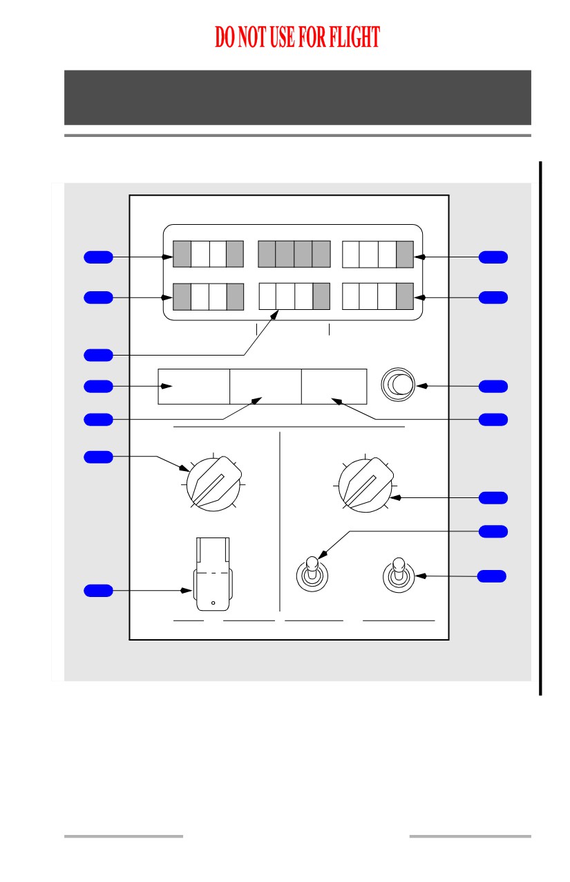
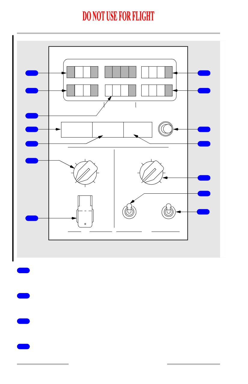
1
DC Ammeter
Indicates amperage of source selected by DC meters selector.
2
DC Voltmeter
Indicates voltage of source selected by DC meters selector.
3
AC Ammeter
Indicates amperage of source selected by AC meters selector.
4
Frequency Meter
Indicates frequency of source selected by AC meters selector.
6.10.2
Electrical -
Controls and Indicators
Boeing 737 Operations Manual
5
AC Voltmeter
Indicates voltage of source selected by AC meters selector.
6
Battery Discharge (BAT DISCHARGE) Light
Illuminated (amber) - with BAT switch ON, excessive battery discharge detected.
7
TR UNIT Light
Illuminated (amber) -
• on the ground - any TR has failed.
• in flight -
• TR1 failed; or
• TR2 and TR3 failed.
8
Electrical (ELEC) Light
Illuminated (amber) - a fault exists in DC power system or standby power system.
Note: Operates only with airplane on ground.
9
Maintenance Test (MAINT) Switch
Used by maintenance.
10
DC Meters Selector
Selects DC source for DC voltmeter and DC ammeter indications.
TEST - used by maintenance.
11
Battery (BAT) Switch
OFF -
• removes power from battery bus and switched hot battery bus when
operating with normal power sources available
• removes power from battery bus, switched hot battery bus, DC standby
bus, static inverter, and AC standby bus when battery is only power
source.
ON (guarded position) -
• provides power to switched hot battery bus
• energizes relays to provide automatic switching of standby electrical
system to battery power with loss of normal power.
12
AC Meters Selector
Selects AC source for AC voltmeter, AC ammeter and frequency meter
indications
6.10.3
Electrical -
Controls and Indicators
Boeing 737 Operations Manual
TEST - used by maintenance.
13
CAB/UTIL Switch
OFF - removes electrical power from cabin recirculation fan, fwd & aft door area
heaters, drain mast heaters, lavatory water heaters, all 115V AC galley busses,
logo lights, potable water compressor, and 115V AC shaver outlets when installed.
ON - supplies electrical power to recirculation fan, fwd & aft door area heaters,
drain mast heaters, lavatory water heaters, all 115V AC galley busses, logo lights,
potable water compressor, and 115V AC shaver outlets when installed.
13
CAB/UTIL Switch
OFF - removes electrical power from left & right recirculation fans, fwd & aft
door area heaters, drain mast heaters, lavatory water heaters, all 115V AC galley
busses, logo lights, potable water compressor, and 115V AC shaver outlets when
installed.
ON - supplies electrical power to left & right recirculation fans, fwd & aft door
area heaters, drain mast heaters, lavatory water heaters, all 115V AC galley
busses, logo lights, potable water compressor, and 115V AC shaver outlets when
installed.
14
IFE/PASS SEAT Switch
OFF - removes electrical power from installed components of the passenger seats
and in-flight entertainment systems including: 115V AC audio entertainment
equipment, 115V AC video entertainment equipment, cabin telephone equipment,
FAX machine, printer, 28V DC video equipment and passenger seat electronic
outlets.
ON - supplies electrical power to installed components of the passenger seats and
in-flight entertainment systems including:
115V AC audio entertainment
equipment, 115V AC video entertainment equipment, cabin telephone equipment,
FAX machine, printer, 28V DC video equipment and passenger seat electronic
outlets.
6.10.4
Electrical -
Controls and Indicators
Boeing 737 Operations Manual
Generator Drive and Standby Power Panel
3
1
STANDBY
2
PWR OFF
1
DRIVE
DRIVE
STANDBY POWER
4
DISCONNECT
DISCONNECT
BAT OFF AUTO
2
FORWARD OVERHEAD PANEL
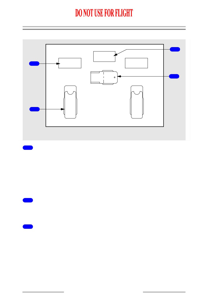
1
Generator Drive (DRIVE) Lights
Illuminated (amber) - Integrated drive generator (IDG) low oil pressure caused by
one of the following:
• IDG failure
• engine shutdown
• IDG automatic disconnect due to high oil temperature
• IDG disconnected through generator drive DISCONNECT switch.
2
Generator Drive Disconnect (DISCONNECT) Switches (guarded)
Disconnects IDG if electrical power is available and engine start lever is in IDLE.
IDG cannot be reconnected in the air.
3
STANDBY Power Off (PWR OFF) Light
Illuminated (amber) - one or more of the following busses are unpowered:
• AC standby bus
• DC standby bus
• battery bus.
6.10.5
Electrical -
Controls and Indicators
Boeing 737 Operations Manual
4
STANDBY POWER Switch
AUTO (guarded position) -
• In flight, or on the ground, and AC transfer busses powered:
• AC standby bus is powered by AC transfer bus 1
• DC standby bus is powered by TR1 and TR2. TR3 is a backup source
• In flight, or on the ground, loss of all AC power
• AC standby bus is powered by battery through static inverter
• DC standby bus is powered by battery.
OFF (center position) -
• STANDBY PWR OFF light illuminates
• AC standby bus, static inverter, and DC standby bus are not powered.
BAT (unguarded position) -
• AC standby bus is powered by battery through static inverter
• DC standby bus and battery bus are powered directly by battery.
6.10.6
Electrical -
Controls and Indicators
Boeing 737 Operations Manual
Ground Power Panel and Bus Switching Panel
GRD POWER
1
AVAILABLE
GRD
PWR
OFF
2
ON
7
BUS TRANSFER
A
O
TRANSFER
U
TRANSFER
F
3
BUS OFF
T
BUS OFF
F
O
SOURCE
SOURCE
4
OFF
OFF
GEN OFF
APU GEN
GEN OFF
5
BUS
OFF BUS
BUS
8
OFF
OFF
6
ON
ON
GEN 1
APU GEN
GEN 2
9
FORWARD OVERHEAD PANEL
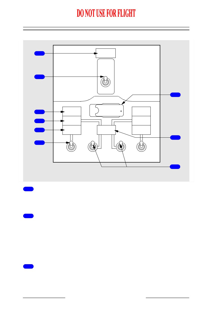
1
Ground Power Available (GRD POWER AVAILABLE) Light
Illuminated (blue) - ground power is connected and meets airplane power quality
standards.
2
Ground Power (GRD PWR) Switch
Three position switch, spring-loaded to neutral
OFF - disconnects ground power from AC transfer busses.
ON - if momentarily moved to ON position and ground power is available:
• removes previously connected power from AC transfer busses
• connects ground power to AC transfer busses if power quality is correct.
3
TRANSFER BUS OFF Lights
Illuminated (amber) - related transfer bus is not powered.
6.10.7
Electrical -
Controls and Indicators
Boeing 737 Operations Manual
4
SOURCE OFF Lights
Illuminated (amber) - no source has been manually selected to power the related
transfer bus, or the manually selected source has been disconnected
• if a source has been selected to power the opposite transfer bus, both
transfer busses are powered.
5
Generator Off Bus (GEN OFF BUS) Lights
Illuminated (blue) - IDG is not supplying power to the related transfer bus.
6
Generator (GEN) Switches
Three position switch, spring-loaded to neutral.
OFF - disconnects IDG from related AC transfer bus by opening generator circuit
breaker.
ON - connects IDG to related AC transfer bus by disconnecting previous power
source and closing generator circuit breaker,
7
BUS TRANSFER Switch
AUTO (guarded position) - BTBs operate automatically to maintain power to AC
transfer busses from any operating generator or external power
• DC cross tie relay automatically provides normal or isolated operation as
required.
OFF - isolates AC transfer bus 1 from AC transfer bus 2 if one IDG is supplying
power to both AC transfer busses
• DC cross tie relay opens to isolate DC bus 1 from DC bus 2.
8
APU Generator Off Bus (GEN OFF BUS) Light
Illuminated (blue) - APU is running and not powering a bus.
9
APU Generator (GEN) Switches
Three position switch, spring-loaded to neutral.
OFF -
• APU generator powering both AC transfer busses
• moving a single APU GEN switch to OFF illuminates related
SOURCE OFF light. APU continues to power AC transfer busses
• subsequently moving other APU GEN switch to OFF disconnects
APU generator from tie bus and removes APU power from AC
transfer busses
• APU generator powering one AC transfer bus; IDG powering one AC
transfer bus
6.10.8
Electrical -
Controls and Indicators
Boeing 737 Operations Manual
• moving related APU GEN switch to OFF disconnects APU generator
from tie bus and AC transfer bus. IDG powers AC transfer busses.
ON -
• Neither AC transfer bus powered by IDG - moving a single APU GEN
switch to ON:
• connects both AC transfer busses to the APU generator
• disconnects external power, if connected
• opposite SOURCE OFF light illuminates until the other APU GEN
switch is moved to ON.
• Both AC transfer busses powered by IDGs - moving an APU GEN switch
ON:
• powers the related AC transfer bus from the APU generator
• other AC transfer bus continues to receive power from the IDG.
Ground Service Switch
1
GROUND
SERVICE
FWD ATTENDANT PANEL
1
GROUND SERVICE Switch
Momentary push-button switch.
Provides manual control of ground service busses. Enables servicing airplane
using external power without activating AC transfer busses.
Illuminated (white) -
• ON - connects external power to ground service busses
• OFF - disconnects external power from ground service busses.
6.10.9
Electrical -
Controls and Indicators
Boeing 737 Operations Manual
Intentionally
Blank
6.10.10
Boeing 737 Operations Manual
Electrical
Chapter 6
System Description
Section 20
Introduction
Single Battery
[Option]
Primary electrical power is provided by two engine integrated drive generators
(IDGs) which supply three-phase, 115 volt, 400 cycle alternating current. Each
IDG supplies its own bus system in normal operation and can also supply essential
and non-essential loads of the opposite side bus system when one IDG is
inoperative. Transformer rectifier (TR) units and a battery/battery charger supply
DC power. The battery also provides backup power for the AC and DC standby
system. The APU operates a generator and can supply power to both AC transfer
busses on the ground or in flight.
There are two basic principles of operation for the 737 electrical system:
• There is no paralleling of the AC sources of power.
• The source of power being connected to a transfer bus automatically
disconnects an existing source.
The electrical power system may be categorized into three main divisions: the AC
power system, the DC power system, and the standby power system.
Dual Battery
[Option]
Primary electrical power is provided by two engine integrated drive generators
(IDGs) which supply three-phase, 115 volt, 400 cycle alternating current. Each
IDG supplies its own bus system in normal operation and can also supply essential
and non-essential loads of the opposite side bus system when one IDG is
inoperative. Transformer rectifier (TR) units and the main battery/battery charger
supply DC power. The main and auxiliary batteries also provide backup power for
the AC and DC standby system. The APU operates a generator and can supply
power to both AC transfer busses on the ground or in flight.
There are two basic principles of operation for the 737 electrical system:
• There is no paralleling of the AC sources of power.
• The source of power being connected to a transfer bus automatically
disconnects an existing source.
The electrical power system may be categorized into three main divisions: the AC
power system, the DC power system, and the standby power system.
6.20.1
Electrical -
System Description
Boeing 737 Operations Manual
Electrical Power Generation
Engine Generators
Primary power is obtained from two engine IDGs. The IDG maintains a constant
generator speed throughout the normal operating range of the engine. An integral
electro-mechanical disconnect device provides for complete mechanical isolation
of the IDG.
APU Generator
The APU generator can supply power to both AC transfer busses on the ground or
in flight. As the only power source, the APU generator can meet electrical power
requirements for all ground conditions and most flight conditions.
External Ground Power
An external AC power receptacle located near the nose gear wheel well, on the
lower right side of the fuselage, allows the use of an external power source. Status
lights on a panel adjacent to the receptacle permit the ground crew to determine if
external power is being used. When connected, external power can supply power
to both transfer busses.
Ground Service
For ground servicing, a ground service switch is on the forward attendant’s panel.
The switch provides ground power directly to the AC ground service busses for
utility outlets, cabin lighting and the battery charger without powering all airplane
electrical busses. The ground service switch is a momentary push button and is
overridden when both AC transfer busses are powered.
6.20.2
Electrical -
System Description
Boeing 737 Operations Manual
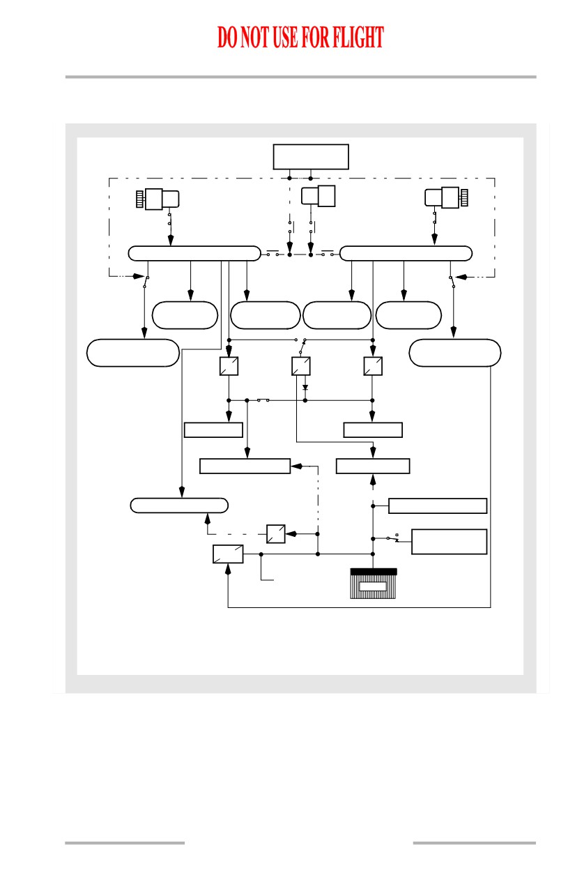
Electrical Power Schematic
[Option - Single battery]
EXTERNAL AC
RECEPTACLE
GEN
GEN
GEN
APU
GEN
GEN
DRIVE
1
2
DRIVE
GCB1
GCB2
AC TRANSFER BUS 1
AC TRANSFER BUS 2
BTB1
BTB2
GND SERVICE
GND SERVICE
RELAY
RELAY
GALLEY
115V AC
115V AC
GALLEY
BUS C & D
MAIN BUS 1
MAIN BUS 2
BUS A & B
115V AC GND
115V AC GND
SERVICE BUS 1
SERVICE BUS 2
TR1
TR3
TR2
CROSS BUS
TIE RELAY
DC BUS 1
DC BUS 2
DC STANDBY BUS
BATTERY BUS
AC STANDBY BUS
HOT BATTERY BUS
INV
SWITCHED
BATT
HOT BAT BUS
CHGR
TO APU STARTER
BAT
Airplane Configuration - In Flight
Battery Switch
- ON
Standby Power Switch - AUTO
Bus Transfer Switch - AUTO
ENGINE GENERATOR CONNECTED TO RELATED BUS
6.20.3
Electrical -
System Description
Boeing 737 Operations Manual
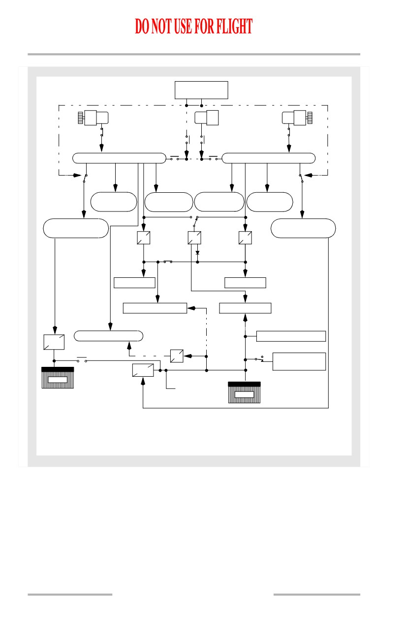
[Option - Dual battery]
EXTERNAL AC
RECEPTACLE
GEN
GEN
GEN
APU
GEN
GEN
DRIVE
1
2
DRIVE
GCB1
GCB2
AC TRANSFER BUS 1
AC TRANSFER BUS 2
BTB1
BTB2
GND SERVICE
GND SERVICE
RELAY
RELAY
GALLEY
115V AC
115V AC
GALLEY
BUS C & D
MAIN BUS 1
MAIN BUS 2
BUS A & B
115V AC GND
115V AC GND
SERVICE BUS 1
SERVICE BUS 2
TR1
TR3
TR2
CROSS BUS
TIE RELAY
DC BUS 1
DC BUS 2
DC STANDBY BUS
BATTERY BUS
AUX
AC STANDBY BUS
HOT BATTERY BUS
BATT
CHGR
INV
SWITCHED
BATT
HOT BAT BUS
CHGR
AUX BAT
TO APU STARTER
BAT
Airplane Configuration - In Flight
Battery Switch
- ON
Standby Power Switch - AUTO
Bus Transfer Switch - AUTO
ENGINE GENERATOR CONNECTED TO RELATED BUS
6.20.4
Electrical -
System Description
Boeing 737 Operations Manual
AC Power System
Each AC power system consists of a transfer bus, a main bus, two galley busses,
and a ground service bus. Transfer bus 1 also supplies power to the AC standby
bus. If the AC source powering either transfer bus fails or is disconnected, the
transfer bus can be powered by any available source through the tie bus with the
bus tie breakers (BTBs).
With the airplane on the ground and both generator control switches OFF, or with
both engines shut down, selecting the GRD PWR switch ON connects external
power to both transfer busses. Likewise, selecting either APU GEN switch ON
connects APU power to both transfer busses. Whichever source is selected last
powers both busses. It is not possible to power one transfer bus with external
power and one transfer bus with APU power.
The transfer busses can be powered from the engine generators by momentarily
positioning the related generator switch to ON. This closes the related generator
circuit breaker (GCB) and connects the generator to the transfer bus. Whenever
external power or APU is powering both transfer busses, and engine generator
power is applied to its onside transfer bus, external power or APU continues to
supply power to the remaining transfer bus.
In flight, each engine generator normally powers its own transfer bus. If an engine
generator is no longer supplying power, the BTBs automatically close to allow the
other engine generator to supply both transfer busses through the tie bus and
BTBs. The APU can power either or both busses through the BTBs.
The system also incorporates an automatic generator on-line feature in case the
airplane takes off with the APU powering both transfer busses. If the APU is either
shut down or fails, the engine generators are automatically connected to their
related transfer busses. This action occurs only once in flight and only under the
circumstances described above.
Bus Tie System
Either generator or the APU can supply power to both transfer busses. If the BUS
TRANS switch is in the AUTO position and the source powering the transfer bus
is disconnected or fails, the source powering the opposite transfer bus
automatically picks up the unpowered transfer bus through the BTBs.
6.20.5