Boeing 737 - 600/700/800/900. Operations Manual (1997 year) - page 32
Automatic Flight -
System Description
Boeing 737 Operations Manual
Intentionally
Blank
4.20.28
Boeing 737 Operations Manual
Communications
Chapter 5
Table of Contents
Section 0
5.0 Communications-Table of Contents
Controls and Indicators
5.10.1
VHF Communication Panel
5.10.1
Radio Tuning Panel
5.10.2
HF Communication Panel
5.10.4
Audio Control Panel (ACP)
5.10.6
Miscellaneous Communication Controls (Typical)
5.10.8
Interphone and Passenger Address Controls
5.10.10
Cockpit Voice Recorder
5.10.11
Cockpit Voice Recorder Switch
5.10.12
Call System
5.10.13
System Description
5.20.1
Introduction
5.20.1
Audio Systems and Audio Control Panels
5.20.1
Speakers and Headsets
5.20.1
Microphones
5.20.2
Normal Audio System Operation
5.20.2
Degraded Audio System Operation
5.20.2
Flight Interphone System
5.20.3
Service (Attendant) Interphone System
5.20.3
Passenger Address System
5.20.3
Call System
5.20.4
VHF Communications
5.20.5
HF Communications
5.20.5
Cockpit Voice Recorder
5.20.6
ACARS System
5.20.6
5.TOC.0.1
Communications -
Table of Contents
Boeing 737 Operations Manual
Intentionally
Blank
5.TOC.0.2
Boeing 737 Operations Manual
Communications
Chapter 5
Controls and Indicators
Section 10
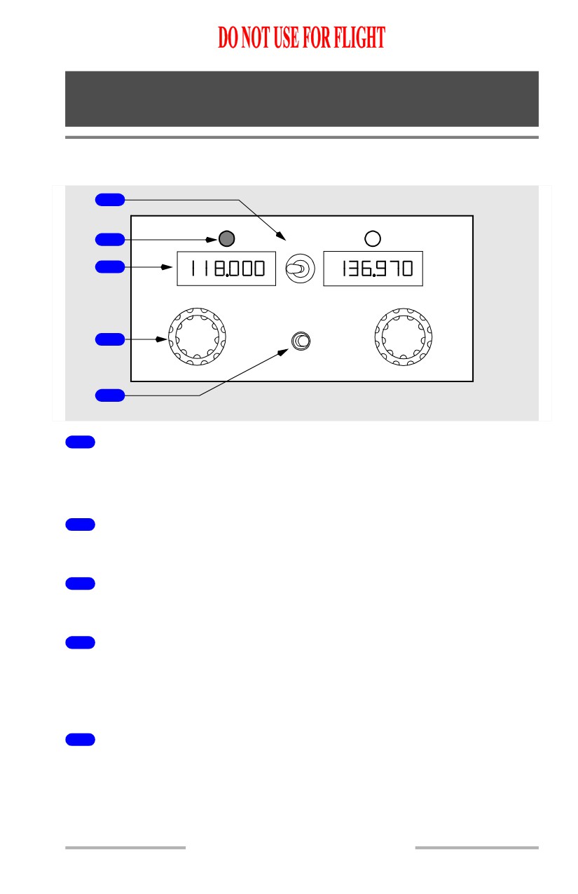
VHF Communication Panel
[Option - Typical VHF control panel with 8.33 khz frequency spacing]
1
2
TFR
3
V
C
FREQ SEL
O
H
M
F
COMM TEST
M
4
5
AFT ELECTRONIC PANEL
1
VHF Communications Transfer (TFR) Switch
Left - selects left frequency as active for transceiver.
Right - selects right frequency as active for transceiver.
2
Active Frequency Light
Illuminated (white)- indicates the related frequency is selected.
3
Frequency Indicator
Indicates selected frequency.
4
Frequency Selector
Rotate - selects frequency in related indicator:
• outer selector changes three left digits
• inner selector changes three right digits.
5
Communication Test (COMM TEST) Switch
Push -
• removes automatic squelch feature, permitting reception of background
noise and thereby testing receiver operation
• improves reception of weak signals.
5.10.1
Communications -
Controls and Indicators
Boeing 737 Operations Manual
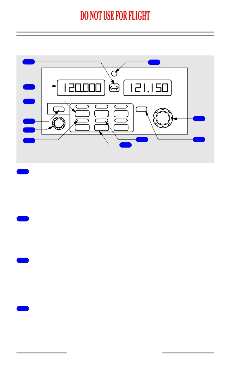
Radio Tuning Panel
[Option -Typical radio tuning panel with 8.33 khz frequency spacing]
1
7
ACTIVE
STANDBY
2
3
P
N
OFF
TEST
L
VHF1
VHF2
VHF3
VHF
8
4
SEN
HF1
AM
HF2
5
6
10
9
11
AFT ELECTRONIC PANEL
1
Frequency Transfer Switch
Push -
• transfers the STANDBY window frequency to the ACTIVE window and
tunes the selected radio to the new active frequency
• transfers the ACTIVE window frequency to the STANDBY window.
2
Frequency Indicator
ACTIVE - displays the tuned frequency of the selected radio.
STANDBY - displays the preselected or previously tuned frequency of
the
selected radio
3
Radio Tuning Switch
Push -
• selects the VHF or HF radio to be tuned
• the tuned frequency is displayed in the ACTIVE frequency indicator
• the standby frequency is displayed in the STANDBY frequency indicator
4
Radio Tuning Panel Off (OFF) Switch
Push -
• disconnects the panel from the communication radios
• switch illuminates (white).
5.10.2
Communications -
Controls and Indicators
Boeing 737 Operations Manual
5
HF Sensitivity Control
Rotate - adjusts the sensitivity of the on-side HF receiver.
6
Radio Tuning Light
Illuminated (white) - indicates the selected radio.
7
Offside Tuning Light
Illuminated (white) -
• the radio normally associated with this panel is being tuned by another
radio tuning panel, or
• the radio tuning panel is being used to tune a radio not normally
associated with this radio tuning panel.
8
Frequency Selector
Rotate - selects frequency in the STANDBY frequency indicator:
• first digit is always 1
• outer selector changes second and third digits in 1 MHz increments
• inner selector changes fourth, fifth, and sixth digits in 8.33 KHz
increments.
9
Communication (VHF) Test (TEST) Switch
Push -
• removes automatic squelch feature, permitting reception of background
noise and thereby testing receiver operation
• improves reception of weak signals.
10
AM Light
Illuminated (white) - HF AM is selected.
Extinguished - HF USB is selected.
11
AM Switch
Push - sets the AM (amplitude modulation) or USB (upper side band) mode for
the selected HF.
5.10.3
Communications -
Controls and Indicators
Boeing 737 Operations Manual
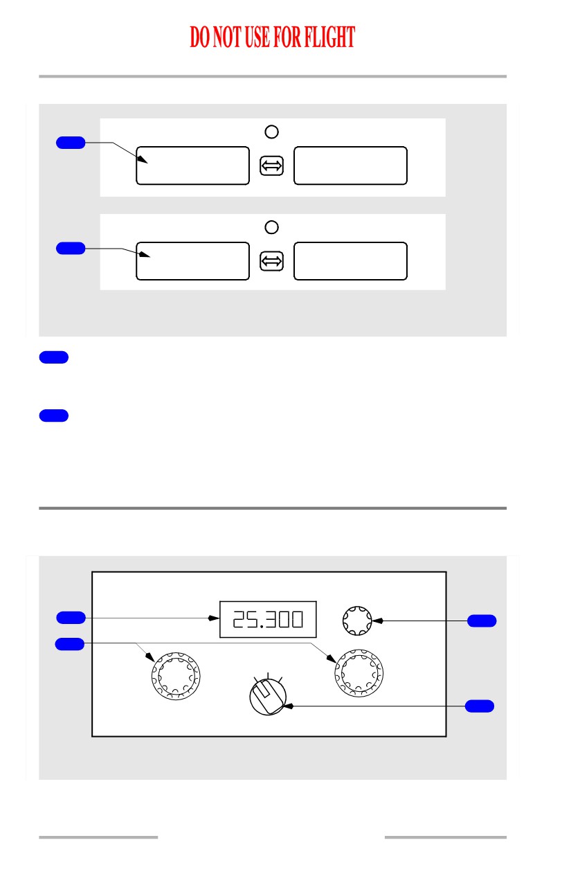
Radio Tuning Panel Fail Modes
ACTIVE
STANDBY
1
INOP
INOP
ACTIVE
STANDBY
2
PANEL
FAIL
AFT ELECTRONIC PANEL
1
INOP Indication
The selected radio is not available.
2
PANEL FAIL
The radio tuning panel has failed.
Note: The selected frequencies may continue to be displayed in the frequency
indicator when the radio is not available.
HF Communication Panel
[Option - Typical HF control panel]
SQUELCH
1
3
C
2
O
H
M
F
OFFUSB AM
M
4
AFT ELECTRONIC PANEL
5.10.4
Communications -
Controls and Indicators
Boeing 737 Operations Manual
1
Frequency Indicator
Displays tuned frequency
Frequency ranges from 2.000 to 29.999 megahertz.
2
Frequency Selectors
Rotate - selects desired frequency.
3
SQUELCH Control
Rotate - controls sensitivity of receiver
• clockwise increases sensitivity of weak or distant stations
• counterclockwise decreases sensitivity to reduce noise or static.
4
Mode Selector
OFF - removes power to transceiver
USB (Upper Sideband) - transmits and receives on the higher side of the
frequency
AM (Amplitude Modulation) - transmits and receives on the selected frequency,
accompanied by a carrier wave.
5.10.5
Communications -
Controls and Indicators
Boeing 737 Operations Manual
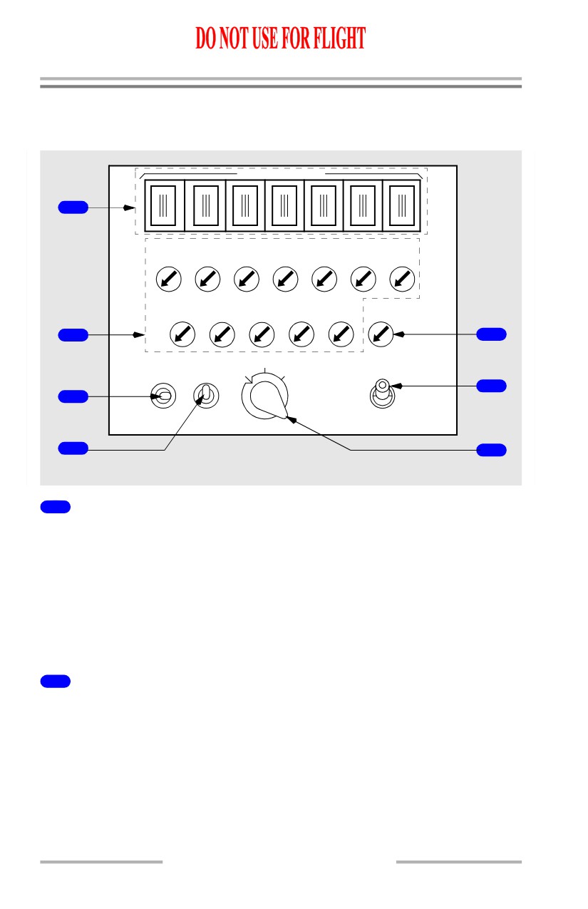
Audio Control Panel (ACP)
[Option - Typical audio control panel with MASK/BOOM and ALT/NORM
switches]
MIC SELECTOR
1
1-VHF-2
-VHF-3
HF
SERV
FLT
PA
INT
INT
1-NAV-2
1-ADF-2
MKR SPKR
2
5
B
R/T MASK V
R
ALT
6
3
I/C BOOM
NORM
4
7
FLIGHT DECK CREW STATIONS
1
Transmitter Selector (MIC SELECTOR) Switches
Illuminated - related switch is active
Push -
• selects related communication system for subsequent transmission
• only one switch may be selected at a time; pushing a second switch
deselects first switch
• reception possible over selected system regardless of whether related
receiver switch is on.
2
Receiver Switches
Illuminated (white) - related switch is active
Rotate - adjusts volume
Push -
• allows reception of related communication system or navigation receiver
• multiple switches may be selected
Push again - deselects related system or receiver.
5.10.6
Communications -
Controls and Indicators
Boeing 737 Operations Manual
3
Push-to-Talk Switch
(spring-loaded to neutral position)
R/T (radio-transmit) - keys oxygen mask or boom microphone for transmission
as selected by transmitter selector.
I/C (Intercom) - keys oxygen mask or boom microphone for direct transmission
over flight interphone and bypasses transmitter selector.
4
MASK-BOOM Switch
MASK - selects oxygen mask microphone for transmissions.
BOOM - selects boom microphone for transmissions.
5
Speaker (SPKR) Switch
Illuminated (white) - SPKR switch is active.
Push - audio from selected receiver is heard on overhead speaker.
Rotate - adjusts overhead speaker volume.
Push again - deselects audio from selected receiver to be heard on overhead
speaker.
6
Alternate-Normal (ALT-NORM) Switch
NORM (Normal) - ACP operates normally.
ALT (Alternate) - ACP operates in degraded mode.
7
Filter Switch
V (Voice) - receive NAV and ADF voice audio.
B (Both) - receive NAV and ADF voice and range audio.
R (Range) - receive NAV and ADF station identifier range (code) audio.
5.10.7
Communications -
Controls and Indicators
Boeing 737 Operations Manual
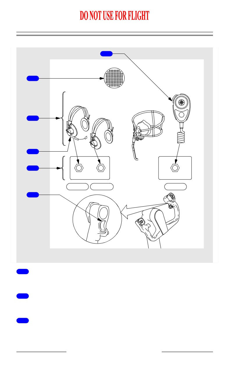
Miscellaneous Communication Controls (Typical)
6
OVERHEAD
SPEAKER
HAND
1
MICROPHONE
(as installed)
BOOM
MICROPHONE/
OXYGEN MASK
HEADSET
MICROPHONE
HEADPHONES
2
3
4
BOOM MIKE HEAD PHONE
HAND MIKE
5
MIC
INT
(view
from
below)
FLIGHT DECK CREW STATIONS
1
Overhead Speaker
Monitors audio from related pilot’s ACP.
2
Headset or Headphones
Monitors audio from related ACP.
3
Standard Microphones
Choose desired microphone for voice transmission through selected radio,
interphone system, or passenger address (PA).
5.10.8
Communications -
Controls and Indicators
Boeing 737 Operations Manual
4
Communication Jacks
Used for appropriate microphone or headphone plugs.
5
Push-To-Talk Switch
MIC (microphone) -
• selects oxygen mask or boom microphone for transmission, as selected by
ACP transmitter selector.
• same as using ACP PTT switch (R/T position).
OFF - center position.
INT (interphone) -
• selects oxygen mask or boom microphone for direct transmission over
flight interphone
• bypasses ACP transmitter selector
• same as using ACP PTT switch (I/C position)
6
Push-To-Talk Switch
Push - keys hand microphone for transmission, as selected by ACP transmitter
selector.
5.10.9
Communications -
Controls and Indicators
Boeing 737 Operations Manual
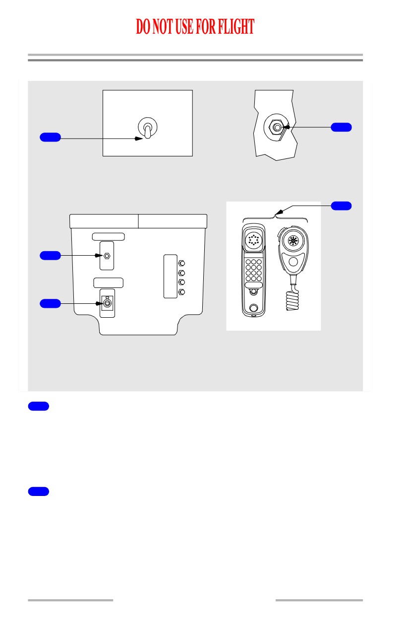
Interphone and Passenger Address Controls
SERVICE
INTER
INTERPHONE
OFF
PHONE
4
1
ON
FLIGHT
AFT OVHD PANEL
EXTERNAL POWER
CONNECTOR PANEL
5
INTERPHONE
2
ELEX
PANEL
LIGHTS
FWD
AFT
CAPT
PASS
CENTER
ADDRESS
F/O
3
FLIGHT DECK CREW
CONTROL STAND
/ ATTENDANT
STATIONS
(As installed)
1
SERVICE INTERPHONE Switch
OFF -
• external jacks are deactivated
• communication between flight deck and flight attendants is still possible.
ON - adds external jacks to service interphone system.
2
Service INTERPHONE Handset Jack
With microphone installed, used to communicate with flight attendant stations:
• with SERVICE INTERPHONE switch ON, also used to communicate
with any external jack location
• bypasses ACP.
5.10.10
Communications -
Controls and Indicators
Boeing 737 Operations Manual
3
Passenger Address (PASS ADDRESS) Hand Microphone Jack
With microphone installed:
• used to make PA announcements
• bypasses ACPs.
4
INTERPHONE FLIGHT Jack
Connects ground crew to flight interphone system.
5
Flight Deck / Attendant PA Hand Microphone
Used to make PA announcements.
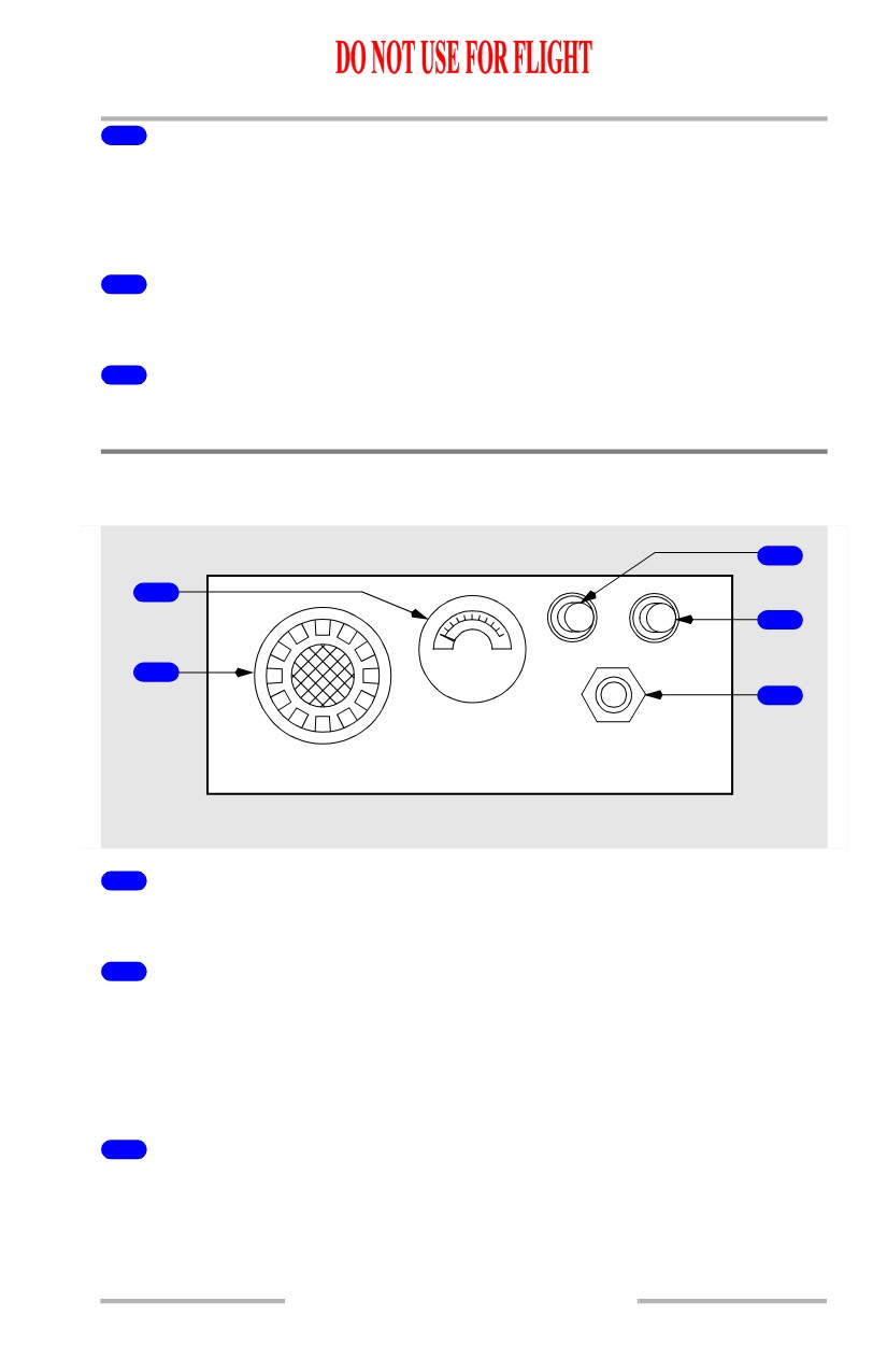
Cockpit Voice Recorder
[Option - Typical]
3
5
2
TEST
ERASE
1
4
HEADSET
600 OHMS
COCKPIT VOICE RECORDER
FORWARD OVERHEAD PANEL
1
Area Microphone
Active anytime 115V AC is applied to airplane.
2
ERASE Switch (red)
Push (2 seconds) -
• all four channels are erased
• monitor indicator momentarily deflects
• operative only when airplane is on ground and parking brake is set.
3
TEST Switch
Push - after a slight delay and no faults are detected:
• monitor indicator rises into green band
• a tone may be heard through a headset plugged into HEADSET jack.
5.10.11
Communications -
Controls and Indicators
Boeing 737 Operations Manual
4
HEADSET Jack
Headset may be plugged into jack to monitor tone transmission during test, or to
monitor playback of voice audio.
5
Monitor Indicator
Pointer deflection indicates:
• during normal operation - system is recording
• during ERASE - erasure on all four channels
(approximately a one second delay)
• during TEST - pointer rises into green band.
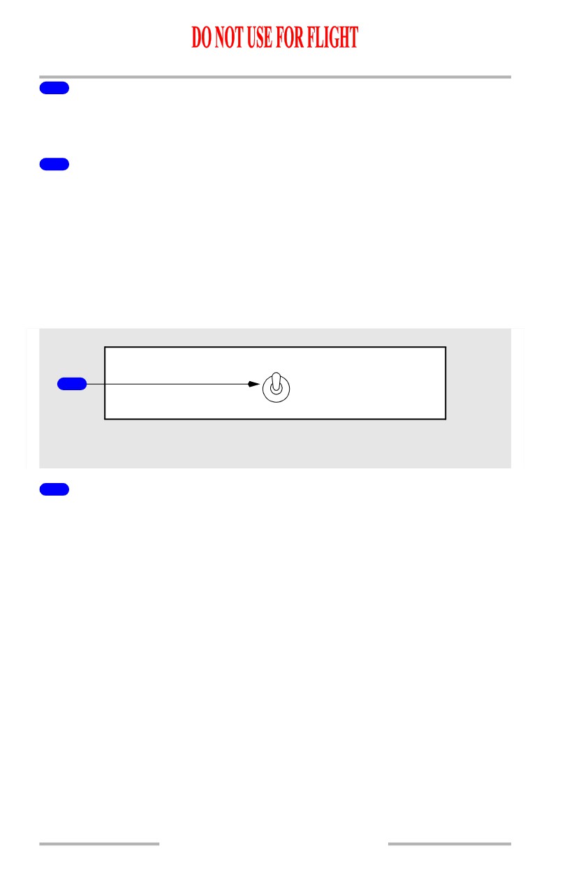
Cockpit Voice Recorder Switch
[Option]
VOICE
AUTO
RECORDER
1
ON
FORWARD OVERHEAD PANEL
1
VOICE RECORDER Switch
AUTO - powers the cockpit voice recorder from first engine start until 5 minutes
after last engine shutdown
ON - powers the cockpit voice recorder until first engine start, then trips the switch
to AUTO.
5.10.12
Communications -
Controls and Indicators
Boeing 737 Operations Manual
Call System
1
GRD
ATTEND
CALL
2
3
CALL
8
PASSENGER CABIN
FORWARD AND AFT
FWD OVHD PANEL
5
PILOT
6
7
4
CALL
ATTENDANT
EXTERNAL POWER
HANDSET
CONNECTOR PANEL
1
Ground Call (GRD CALL) Switch
Push - sounds a horn in nose wheel well until released.
2
Attendant Call (ATTEND) Switch
Push -
• sounds a two-tone chime in passenger cabin
• illuminates both pink master call lights.
3
Flight Deck CALL Light
Illuminated (blue) - flight deck is being called by flight attendants or ground crew.
4
PILOT CALL Switch
Push - sounds a single-tone chime in flight deck.
5
CAPTAIN Call Switch
Push - sounds a single-tone chime in flight deck.
5.10.13
Communications -
Controls and Indicators
Boeing 737 Operations Manual
6
ATTENDANT Call Switch
Push -
• sounds a two-tone chime in passenger cabin
• illuminates both pink master call lights.
7
Call RESET Switch
Push -
• extinguishes both pink master call lights
• cancels call
• disconnects the handset from the public address system.
8
Master Call Lights
Illuminated -
• amber - a lavatory call switch is activated or smoke is detected in a
lavatory.
• pink - flight deck or other flight attendant station is calling.
• blue - a passenger seat call switch is activated.
5.10.14
Boeing 737 Operations Manual
Communications
Chapter 5
System Description
Section 20
Introduction
The communication system includes:
• radio communication system
• interphone communication system
• cockpit voice recorder system
• communication crew alerting system
The communication systems are controlled using the:
• audio control panels
[Option - Radio tuning panel]
• radio tuning panels
[Option - VHF or HF control panels]
• radio communication panels
Audio Systems and Audio Control Panels
An ACP is installed at the Captain, First Officer, and Observer stations. Each
panel controls an independent crew station audio system and allows the
crewmember to select the desired radios, navigation aids, interphones, and PA
systems for monitoring and transmission.
Transmitter selectors on each ACP select one radio or system for transmission by
that crewmember. Any microphone at that crew station may then be keyed to
transmit on the selected system.
Receiver switches select the systems to be monitored. Any combination of
systems may be selected. Receiver switches also control the volume for the
headset and speaker at the related crew stations. Audio from each ACP is
monitored using a headset/headphones or the related pilot’s speaker.
Audio warnings for altitude alert, ground proximity warning, collision avoidance,
and windshear are also heard through the speakers and headsets at preset volumes.
They cannot be controlled or turned off by the crew.
Speakers and Headsets
Each crew station has a headset or headphone jack. The Captain and First Officer
have speakers on the ceiling above their seats. There is no speaker at the observer
station. Headset volume is controlled by the receiver switches. Speaker volume is
controlled by the receiver switches and also the speaker switch.
5.20.1
Communications -
System Description
Boeing 737 Operations Manual
Microphones
Hand microphones and boom microphones may be plugged into the related jacks
at the flight deck crew stations. Each oxygen mask also has an integral
microphone.
The MASK-BOOM switch allows selection of the oxygen mask microphone or
the boom microphone. The MASK-BOOM switch does not affect the operation
of the hand microphone.
Each hand microphone has a PTT switch to key the selected audio system. The
PTT switches on the control wheel or ACP are used to key the oxygen mask or
boom microphone, as selected by the R/T and I/C switch. The R/T and I/C switch
does not affect the operation of the hand microphone.
Normal Audio System Operation
The Captain, First Officer, and Observer audio systems are located in a common
remote electronics unit in the E/E compartment. They function independently and
have separate circuit breakers. The audio systems are normally controlled by the
related ACPs through digital or computerized control circuits.
Degraded Audio System Operation
If the remote electronics unit or ACP malfunctions, the ACP cannot control the
remote electronics unit. Audio system operation can be switched to a degraded
mode by placing the ALT-NORM switch to ALT. In this mode, the ACP at that
station is inoperative and the crewmember can only communicate on one radio.
The ACP transmitter selectors are not functional. Any transmission from that
station must be from the radio shown on the chart below. The transmitter selector
for the usable radio illuminates when a station is operating in the degraded mode.
The receiver switches are not functional, and only the usable radio is heard at a
preset volume, through the headset. The speaker and speaker switch are not
functional at that station. In addition, the flight interphone and service interphone
cannot be used. The control wheel PTT switch INT position and the ACP PTT
switch I/C position are not functional since the flight interphone is not functional.
The mask and boom microphones can be used for transmission on the usable
radio. The MASK-BOOM switch works normally in the degraded mode. The
mask and boom microphones can be keyed with the control wheel PTT switch
MIC position or the ACP PTT switch R/T position. The hand microphone is not
usable in the degraded mode of operation.
Audio warnings for altitude alert, GPWS, and windshear are not heard on an audio
system operating in the degraded mode.
5.20.2

Communications -
System Description
Boeing 737 Operations Manual
An audio system operating in the degraded mode cannot access the passenger
address system through the audio control panel. The crewmember can still use the
service interphone handset and PA microphone if they are installed on the control
stand.
CREW STATION AUDIO SYSTEM IN
RADIO AVAILABLE FOR
DEGRADED MODE
TRANSMISSION AND RECEPTION
AT DEGRADED STATION
CAPTAIN
VHF-1
FIRST OFFICER
VHF-2
OBSERVER
VHF-1
Flight Interphone System
The flight interphone system is an independent communication network. Its
primary purpose is to provide private communication between flight deck
crewmembers without intrusion from the service interphone system. The ground
crew may also use the flight interphone through a jack at the external power
receptacle.
The pilots can transmit directly over the flight interphone by using the control
wheel PTT switch. Alternately, any crewmember with an ACP can
transmit/receive over the flight interphone by using their related ACP and normal
PTT switches. Any standard microphone may be used with the flight interphone
system.
Service (Attendant) Interphone System
The service interphone system provides intercommunication between the flight
deck, Flight Attendants, and ground personnel. Flight deck crewmembers
communicate using either a separate handset (if installed) or their related ACP and
any standard microphone.
The Flight Attendants communicate between flight attendant stations or with the
flight deck using any of the attendant handsets. Anyone who picks up a
handset/microphone is automatically connected to the system.
External jacks for use by maintenance or service personnel can be added to the
system by use of the service interphone switch.
Passenger Address System
The passenger address (PA) system allows flight deck crewmembers and flight
attendants to make announcements to the passengers. Announcements are heard
through speakers located in the cabin and in the lavatories.
5.20.3