Boeing 737 - 600/700/800/900. Operations Manual (1997 year) - page 31
Automatic Flight -
System Description
Boeing 737 Operations Manual
CWS R with a CMD engage switch illuminated can be used to capture a selected
radio course while the VOR/LOC or APP mode is armed. Upon intercepting the
radial or localizer, the F/D and A/P annunciations change from CWS R to
VOR/LOC engaged, and the A/P tracks the selected course.
Autothrottle System
The A/T system provides automatic thrust control from the start of takeoff through
climb, cruise, descent, approach and go-around or landing. In normal operation,
the FMC provides the A/T system with N1 limit values.
The A/T moves the thrust levers with a separate servo motor on each thrust lever.
Manually positioning the thrust levers does not cause A/T disengagement unless
10 degrees of thrust lever separation is exceeded during a dual channel approach
after FLARE armed is annunciated. Following manual positioning, the A/T may
reposition the thrust levers to comply with computed thrust requirements except
while in the THR HLD and ARM modes.
The A/T system operates properly with the EECs ON or in ALTN. In either case,
the A/T uses the FMC N1 limits. During A/T operation, it is recommended that
both EECs be ON or both be in ALTN, as this produces minimum thrust lever
separation.
A/T Engagement
Moving the A/T Arm switch to ARM, arms the A/T for engagement in the N1,
MCP SPD or FMC SPD mode. The A/T Arm switch is magnetically held at ARM
and releases to OFF when the A/T becomes disengaged.
A general summary of A/T mode engagement is as follows:
• A/T SPD or N1 modes automatically engage when AFDS command pitch
modes become engaged
• engaging LVL CHG or VNAV climb modes automatically engages the
A/T N1 mode
• engaging LVL CHG or VNAV descent modes automatically engages the
A/T in RETARD and then ARM when thrust is at idle
• if not in a VNAV mode, engagement of ALT ACQ or ALT HOLD
automatically engages the A/T in the MCP SPD mode; otherwise the A/T
remains in FMC SPD
• engagement of G/S capture automatically engages the A/T in the MCP
SPD mode.
Autothrottle Disengagement
Any of the following conditions or actions disengages the A/T:
• moving the A/T Arm switch to OFF
• pushing either A/T Disengage switch
4.20.8
Automatic Flight -
System Description
Boeing 737 Operations Manual
• an A/T system fault is detected
• two seconds have elapsed since landing touchdown
• thrust levers become separated more than 10 degrees during a dual
channel approach after FLARE armed is annunciated
• significant thrust difference along with control wheel roll input of 10
degrees or more, and flap position up through 10.
A/T disengagement is followed by A/T Arm switch releasing to OFF and flashing
red A/T Disengage lights. The A/T Disengage lights do not illuminate when the
A/T automatically disengages after landing touchdown.
Automatic Flight Operations
The phases of flight for automatic flight operations are:
• Takeoff and climb
• Approach and landing
• Enroute
• Go-around
Automatic Flight Takeoff and Climb
Takeoff is a flight director only function of the TO/GA mode. Flight director pitch
and roll commands are displayed and the autothrottle maintains takeoff N1 thrust
limit as selected from the FMC. The autopilot may be engaged after takeoff.
[Option - Flight director commands wings level on takeoff]
Both F/Ds must be ON to engage the takeoff mode prior to starting the takeoff.
The F/D takeoff mode is engaged by pushing the TO/GA switch on either thrust
lever. The FMAs display FD as the A/P status, TO/GA as the pitch mode, and
blank for the roll mode.
[Option - Flight director commands HDG SEL on takeoff]
Both F/Ds must be ON to engage the takeoff mode prior to starting the takeoff.
The F/D takeoff mode is engaged by pushing the TO/GA switch on either thrust
lever. The FMAs display FD as the A/P status, TO/GA as the pitch mode, and
HDG SEL as the roll mode.
During takeoff, pushing a TO/GA switch engages the autothrottle in the N1 mode.
The A/T annunciation changes from ARM to N1 and thrust levers advance toward
takeoff thrust.
The F/D can also be engaged in the takeoff mode with the F/D switches off. If a
TO/GA switch is pushed after 80 knots below 2000 feet AGL and prior to 150
seconds after lift-off, the F/D command bars automatically appear for both pilots.
[Option - Flight director commands wings level on takeoff]
During takeoff, prior to 60 KIAS:
• the pitch command is 10 degrees nose down
• the roll command is wings level
• the autothrottle is engaged in the N1 mode
4.20.9
Automatic Flight -
System Description
Boeing 737 Operations Manual
• thrust levers advance until the engines reach takeoff thrust
• the FMAs display N1 for the autothrottle mode, TO/GA for the pitch
mode, and blank for the roll mode.
[Option - Flight director commands HDG SEL on takeoff]
During takeoff, prior to 60 KIAS:
• the pitch command is 10 degrees nose down
• the roll command is HDG SEL
• the autothrottle is engaged in the N1 mode
• thrust levers advance until the engines reach takeoff thrust
• the FMAs display N1 for the autothrottle mode, TO/GA for the pitch
mode, and HDG SEL for the roll mode.
At 60 knots, the F/D pitch commands 15 degrees nose up.
At 84 knots, the A/T mode annunciates THR HLD.
At lift-off:
• the pitch command continues at 15 degrees until sufficient climb rate is
acquired. Pitch then commands MCP speed (normally V2) plus 20 knots
• if an engine failure occurs during takeoff, the pitch command target speed
is:
• V2, if airspeed is below V2
• existing speed, if airspeed is between V2 and V2 + 20
• V2 + 20, if airspeed is above V2 + 20
[Option - Flight director commands wings level on takeoff]
• the roll command maintains wings level.
[Option - Flight director commands HDG SEL on takeoff]
[Option - Honeywell -904/-905 FCC]
• the roll command maintains HDG SEL. Bank angle is limited to 8 degrees
until 200 feet AGL.
After lift-off:
• the A/T remains in THR HLD until 800 feet RA. A/T annunciation then
changes from THR HLD to ARM and reduction to climb thrust can be
made by pushing the N1 switch
[Option - Without automatic thrust reduction after takeoff]
• automatic thrust reduction to climb power occurs when VNAV, ALT ACQ
or ALT HOLD is engaged. Until 2 1/2 minutes after liftoff, automatic
thrust reduction is inhibited when engaging LVL CHG or V/S modes
4.20.10
Automatic Flight -
System Description
Boeing 737 Operations Manual
[Option - Automatic thrust reduction after takeoff, FMC update 10.1 and later]
• automatic reduction to climb thrust occurs upon reaching the selected
thrust reduction altitude which is shown on the FMC CDU TAKEOFF
REF page 2/2 during preflight, or when the airplane levels off in ALT
HOLD or VNAV PTH. Pilot entries can be made to override the default
value. Allowable entries are 800 feet to 9999 feet
• flight director engaged status is terminated by engaging an autopilot in
CMD (CMD replaces FD in A/P status display)
• pitch engages in LVL CHG and pitch mode FMA is MCP SPD unless
another pitch mode has been selected
• MCP IAS/Mach display and airspeed cursor change to V2 + 20 knots
• roll mode engages in HDG SEL unless another roll mode has been
selected.
To terminate the takeoff mode below 400 feet RA, both F/D switches must be
turned OFF. Above 400 feet RA, selection of another pitch mode or engaging an
autopilot will terminate the takeoff mode; other F/D roll modes can be also
selected.
4.20.11
Automatic Flight -
System Description
Boeing 737 Operations Manual
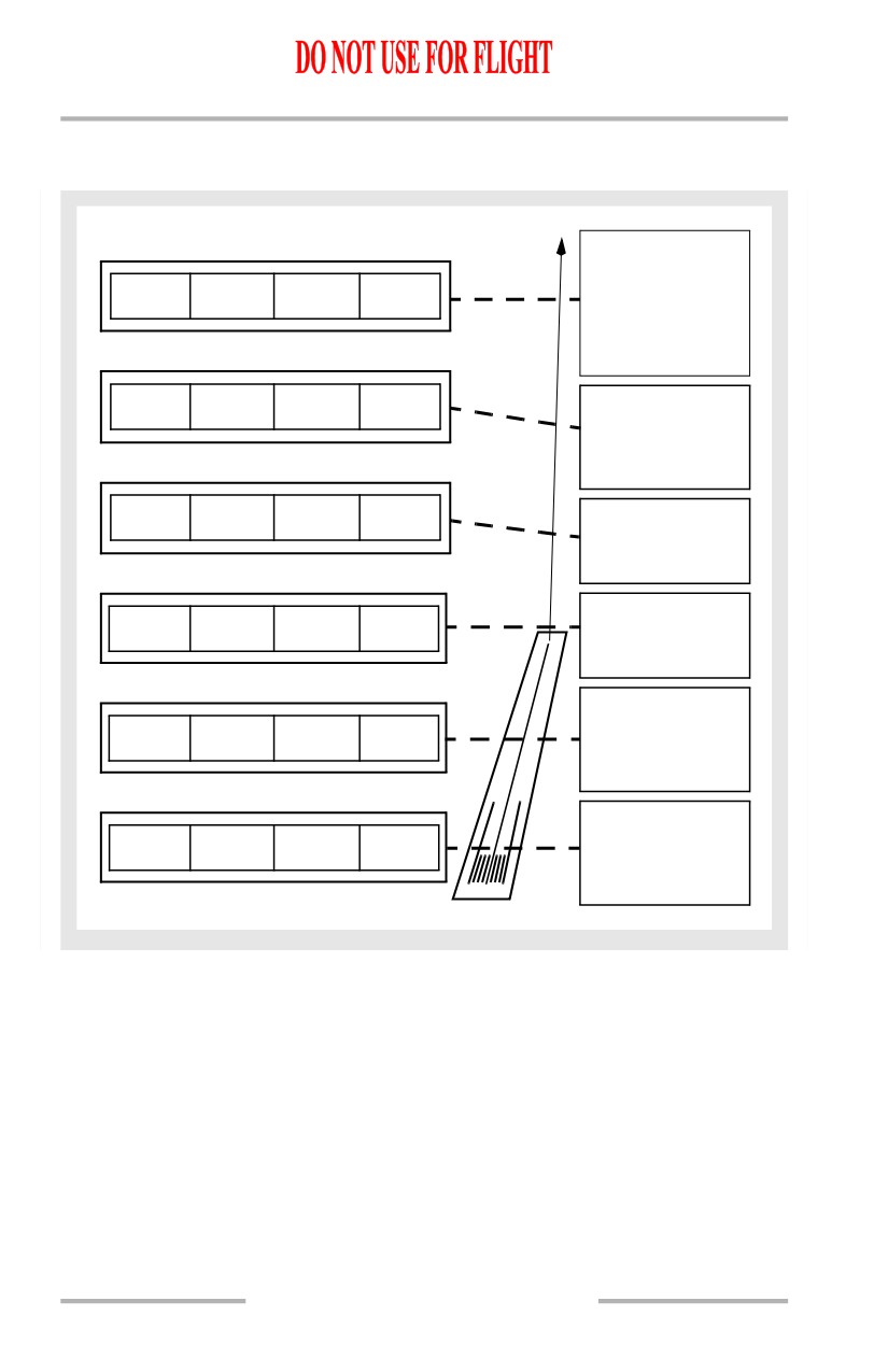
Automatic Flight Takeoff Profile
[Option - EFIS/MAP, flight director commands wings level on takeoff]
Engage A/P
• A/P engages in
N1
MCP SPD
LNAV
CMD
CMD
• Pitch mode
engages in
MCP SPD
N1
TO/GA
LNAV
FD
Thrust Reduction
• A/T N1 mode
engages at
CLB power
ARM
TO/GA
LNAV
FD
800 ft RA -
• A/T ARM
mode engages
Above 400 ft RA
THR HLD
TO/GA
LNAV
FD
• Select roll
mode
84 knots -
THR HLD
TO/GA
FD
• A/T THR
HLD mode
engages
Push TO/GA
Switch
N1
TO/GA
FD
(both FD ON and
A/T armed)
4.20.12
Automatic Flight -
System Description
Boeing 737 Operations Manual
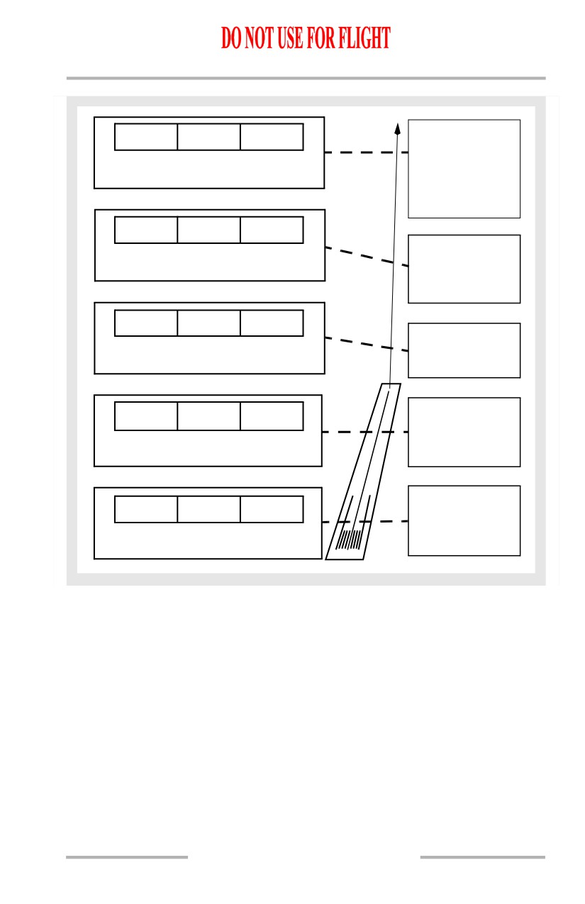
[Option - PFD/ND, flight director commands HDG SEL on takeoff]
Engage A/P
N1
HDG SEL
MCP SPD
• A/P engages in
CMD
CMD
• Pitch mode
engages in
MCP SPD
N1
HDG SEL
TO/GA
Thrust Reduction
• A/T N1 mode
FD
engages at
CLB power
ARM
HDG SEL
TO/GA
800 ft RA -
• A/T ARM
FD
mode engages
84 knots -
THR HLD
HDG SEL
TO/GA
• A/T THR
HLD mode
FD
engages
Push TO/GA
N1
HDG SEL
TO/GA
Switch
(both FD ON and
FD
A/T armed)
Automatic Flight En Route
The autopilot and/or the flight director can be used after takeoff to fly a lateral
navigation track (LNAV) and a vertical navigation track (VNAV) provided by the
FMC.
Other roll modes available are:
• VOR course (VOR/LOC)
• heading select (HDG SEL).
Other pitch modes available are:
• altitude hold (ALT HOLD)
• level change (MCP SPD)
• vertical speed (V/S).
4.20.13
Automatic Flight -
System Description
Boeing 737 Operations Manual
Automatic Flight Approach and Landing
The AFDS provides guidance for single A/P non-precision approaches. The
VOR/LOC switch arms the AFDS for VOR or localizer tracking. Descent may be
accomplished using VNAV, LVL CHG, or V/S. VOR/LOC, LNAV, or HDG SEL
may be used for the roll mode.
The AFDS provides guidance for single or dual A/P precision approaches. The
approach mode arms the AFDS to capture and track the localizer and glideslope.
Approach (APP) Mode Dual A/Ps
Approach mode allows both A/Ps to be engaged at the same time. Dual A/P
operation provides fail passive operation through landing flare and touchdown or
an automatic go-around. During fail passive operation, the flight controls respond
to the A/P commanding the lesser control movement. If a failure occurs in one
A/P, the failed channel is counteracted by the second channel such that both A/Ps
disconnect with minimal airplane maneuvering and with aural and visual
warnings to the pilot.
One VHF NAV receiver must be tuned to an ILS frequency before the approach
mode can be selected. For a dual A/P approach, the second VHF NAV receiver
must be tuned to the ILS frequency and the corresponding A/P engaged in CMD
prior to 800 feet RA.
Localizer and Glideslope Armed
After setting the localizer frequency and course, pushing the APP switch selects
the APP mode. The APP switch illuminates and VOR/LOC and G/S annunciate
armed. The APP mode permits selecting the second A/P to engage in CMD. This
arms the second A/P for automatic engagement after LOC and G/S capture and
when descent below 1500 RA occurs.
The localizer can be intercepted in the HDG SEL, CWS R or LNAV mode.
[Option - G/S capture inhibited before LOC capture]
Glideslope (G/S) capture is inhibited prior to localizer capture.
Localizer Capture
[Option - EFIS/MAP]
The LOC capture point is variable and depends on intercept angle and rate of
closure, but does not occur at less than 1/2 dot. Upon LOC capture, VOR/LOC
annunciates captured, 1 CH is annunciated for A/P status, the previous roll mode
disengages and the airplane turns to track the LOC.
4.20.14
Automatic Flight -
System Description
Boeing 737 Operations Manual
[Option - PFD/ND]
The LOC capture point is variable and depends on intercept angle and rate of
closure, but does not occur at less than 1/2 dot. Upon LOC capture, VOR/LOC
annunciates captured, SINGLE CH is annunciated for A/P status, the previous roll
mode disengages and the airplane turns to track the LOC.
Glideslope Capture
[Option - G/S capture inhibited before LOC capture]
Glideslope capture is inhibited prior to localizer capture.
The G/S can be captured from above or below. Capture occurs at 2/5 dot and
results in the following:
• G/S annunciates captured
• previous pitch mode disengages
• APP light extinguishes if localizer has also been captured
• airplane pitch tracks the G/S
• GA displayed on thrust mode display (N1 thrust limit).
After VOR/LOC and G/S are both captured, the APP mode can be exited by:
• pushing a TO/GA switch
• disengaging A/P and turning off both F/D switches
• retuning a VHF NAV receiver.
After LOC and G/S Capture
Shortly after capturing LOC or G/S and below 1500 feet RA:
• the second A/P couples with the flight controls
• test of the ILS deviation monitor system is performed and the G/S or LOC
display turns amber and flashes
• FLARE armed is annunciated
[Option - EFIS/MAP]
• the 1 CH annunciation extinguishes
[Option - PFD/ND]
• the SINGLE CH annunciation extinguishes
• A/P go-around mode arms but is not annunciated.
[Option - CWS deactivated on approach]
Note: After localizer and glideslope capture during a dual autopilot approach,
CWS cannot be engaged by manually overriding pitch and roll. Manual
override of autopilots causes autopilot disengagement.
The A/Ps disengage and the F/D command bars retract to indicate an invalid ILS
signal.
4.20.15
Automatic Flight -
System Description
Boeing 737 Operations Manual
800 Feet Radio Altitude
The second A/P must be engaged in CMD by 800 feet RA to execute a dual
channel A/P approach. Otherwise, CMD engagement of the second A/P is
inhibited.
400 Feet Radio Altitude
The stabilizer is automatically trimmed an additional amount nose up. If the A/Ps
subsequently disengage, forward control column force may be required to hold the
desired pitch attitude.
If FLARE is not armed by approximately 350 feet RA, both A/Ps automatically
disengage.
Flare
The A/P flare maneuver starts at approximately 50 feet RA and is completed at
touchdown:
• FLARE engaged is annunciated and F/D command bars retract
• the stabilizer is automatically trimmed an additional amount nose up at 50
feet RA.
• the A/T begins retarding thrust at approximately 27 feet RA so as to reach
idle at touchdown. A/T FMA annunciates RETARD.
• the A/T automatically disengages approximately 2 seconds after
touchdown.
• the A/P must be manually disengaged after touchdown. Landing rollout is
executed manually after disengaging the A/P.
Approach (APP) Mode Single A/P
A single A/P ILS approach can be executed by engaging only one A/P in CMD
after pushing the APP mode select switch. Single A/P approach operation is the
same as dual, with the following exceptions:
• full automatic flare and touchdown capability is not available. FLARE is
not annunciated and stabilizer trim bias is not applied
[Option - EFIS/MAP]
• A/P status of 1 CH is annunciated for the entire approach after localizer
capture
[Option - PFD/ND]
• A/P status of SINGLE CH is annunciated for the entire approach after
localizer capture
• an A/P go-around is not available.
4.20.16
Automatic Flight -
System Description
Boeing 737 Operations Manual
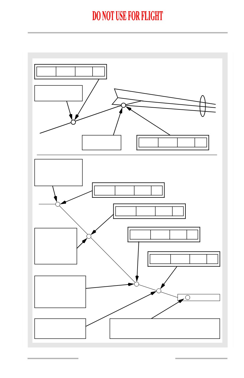
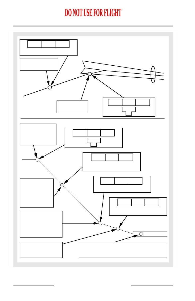
Automatic Flight Approach Profile
[Option - EFIS/MAP]
MCP SPD
ALT HLD
HDG SEL
CMD
G/S
VOR/LOC
Select APP
Second A/P CMD
LOC capture
MCP SPD
ALT HLD
VOR/LOC
CMD
Set heading
G/S
1 CH
G/S Capture
• GA displayed
on Thrust
Mode Display
MCP SPD
G/S
VOR/LOC
CMD
1 CH
MCP SPD
G/S
VOR/LOC
CMD
FLARE
Below 1500 ft
MCP SPD
FLARE
VOR/LOC
CMD
RA
• Go-around
mode armed
but not
RETARD
FLARE
VOR/LOC
CMD
annunciated
50 ft RA
• FLARE
maneuver begins
• F/D bars retract
from view
27 ft RA
Touchdown
• A/T retards to
• Manually disconnect A/P
idle
• A/T disconnects 2 seconds after touchdown
4.20.17
Automatic Flight -
System Description
Boeing 737 Operations Manual
[Option - PFD/ND]
MCP SPD
HDG SEL ALT HLD
VOR/LOC
G/S
CMD
Select APP
Second A/P CMD
MCP SPD
VOR/LOC
ALT HLD
LOC capture
G/S
Set heading
SINGLE
CH
G/S Capture
• GA displayed
MCP SPD
VOR/LOC
G/S
on Thrust
Mode Display
SINGLE
CH
MCP SPD
VOR/LOC
G/S
FLARE
CMD
MCP SPD
VOR/LOC
FLARE
Below 1500 ft
RA
CMD
• Go-around
mode armed
but not
RETARD
VOR/LOC
FLARE
annunciated
CMD
50 ft RA
• FLARE
maneuver begins
• F/D bars retract
from view
27 ft RA
Touchdown
• A/T retards to
• Manually disconnect A/P
idle
• A/T disconnects 2 seconds after touchdown
4.20.18
Automatic Flight -
System Description
Boeing 737 Operations Manual
Go-Around
Go-Around (GA) mode is engaged by pushing either TO/GA switch. An A/P
go-around requires dual A/P operation and is armed when FLARE armed is
annunciated. If both A/Ps are not operating, a manual F/D go-around is available.
With the A/T Arm switch at ARM, the A/T go-around mode is armed:
• when descending below 2000 feet RA
[Option - A/P auto disengages for TO/GA above 2000 feet RA]
[Option - Honeywell -708 FCC]
• when above 2000 feet RA with flaps down or G/S captured
• with or without the AFDS engaged.
A/P Go-Around
The A/P GA mode requires dual A/P operation and is available after FLARE
armed is annunciated and prior to the A/P sensing touchdown.
With the first push of either TO/GA switch:
• A/T (if armed) engages in GA and the A/T Engaged Mode annunciation
on the FMA indicates GA
• thrust advances toward the reduced go-around N1 to produce 1000 to
2000 fpm rate of climb
• pitch mode engages in TO/GA and the Pitch Engaged Mode annunciation
on the FMA indicates TO/GA
• F/D pitch commands 15 degrees nose up until reaching programmed rate
of climb. F/D pitch then commands target airspeed for each flap setting
based on maximum takeoff weight calculations
• F/D roll commands hold current ground track. The Roll Engaged Mode
annunciation on the FMA is blank
• the IAS/Mach display blanks
• the command airspeed cursor automatically moves to a target airspeed for
the existing flap position based on maximum takeoff weight calculations.
Note: If the go-around mode is selected after touchdown and prior to A/T
disengagement, the A/Ps disengage and the A/Ts may command GA thrust.
With the second push of either TO/GA switch after A/T reaches reduced
go-around thrust:
• the A/T advances to the full go-around N1 limit.
TO/GA mode termination from A/P go-around:
• below 400 feet RA, the AFDS remains in the go-around mode unless both
A/Ps and F/Ds are disengaged
• above 400 feet RA, select a different pitch or roll mode.
• if the roll mode is changed first:
4.20.19
Automatic Flight -
System Description
Boeing 737 Operations Manual
• the selected mode engages in single A/P roll operation and is
controlled by the A/P which was first in CMD
• pitch remains in dual A/P control in TO/GA mode.
• if the pitch mode is changed first:
• the selected mode engages in single A/P pitch operation and is
controlled by the A/P which was first in CMD
• the second A/P disengages
• the roll mode engages in CWS R.
• the A/T GA mode is terminated when:
• another pitch mode is selected
• ALT ACQ annunciates engaged.
Note: The pitch mode cannot be changed from TO/GA until sufficient
nose-down trim has been input to allow single channel A/P operation.
This nose-down trim is automatically added by the A/P to reset the trim
input made by the A/P at 400 feet RA and at 50 feet RA during the
approach.
With pitch mode engaged in TO/GA, ALT ACQ engages when approaching the
selected altitude and ALT HOLD engages at the selected altitude if the stabilizer
position is satisfactory for single A/P operation.
• if stabilizer trim position is not satisfactory for single A/P operation:
• ALT ACQ is inhibited
• A/P disengage lights illuminate steady red
• pitch remains in TO/GA.
Note: To extinguish A/P disengage lights, disengage A/Ps or select higher
altitude on MCP.
F/D Go-Around
If both A/Ps are not engaged, a manual F/D only go-around is available under the
following conditions:
• inflight below 2000 feet RA
[Option - A/P auto disengages for TO/GA above 2000 feet RA]
[Option - Honeywell -708 FCC]
• inflight above 2000 feet RA with flaps down or G/S captured
• not in takeoff mode.
With the first push of either TO/GA switch:
• A/T (if armed) engages in GA and advances thrust toward the reduced
go-around N1 to produce 1000 to 2000 fpm rate of climb. The A/T
Engaged Mode annunciation on the FMA indicates GA
• autopilot (if engaged) disengages
• pitch mode engages in TO/GA and the Pitch Engaged Mode annunciation
on the FMA indicates TO/GA
4.20.20
Automatic Flight -
System Description
Boeing 737 Operations Manual
• F/D pitch commands 15 degrees nose up until reaching programmed rate
of climb. F/D pitch then commands target airspeed for each flap setting
based on maximum takeoff weight calculations
• F/D roll commands approach ground track at time of engagement. The
Roll Engaged Mode annunciation on the FMA is blank
• the IAS/Mach display blanks
• the command airspeed cursor automatically moves to a target airspeed for
the existing flap position based on maximum takeoff weight calculations.
With the second push of either TO/GA switch (if A/T engaged and after A/T
reaches reduced go-around thrust):
• the A/T advances to the full go-around N1 limit
TO/GA mode termination from F/D go-around:
• below 400 feet RA, both F/D switches must be turned off.
• above 400 feet RA, select a different pitch or roll mode.
• if the roll mode is changed first:
• F/D roll engages in the selected mode
• the F/D pitch mode remains in TO/GA.
• if the pitch mode is changed first:
• the F/D roll mode automatically changes to HDG SEL
• F/D pitch engages in the selected mode.
• the A/T GA mode (if engaged) is terminated when:
• another pitch mode is selected
• ALT ACQ annunciates engaged.
Note: Engaging an A/P in CMD automatically engages the A/P and F/Ds in
LVL CHG for pitch and HDG SEL for roll.
Single Engine F/D Go-Around
With a push of either TO/GA switch:
• F/D roll commands hold current ground track. The Roll Engaged Mode
annunciation on the FMA is blank
• pitch mode engages in TO/GA and the Pitch Engaged Mode annunciation
on the FMA indicates TO/GA
• the F/D target speed is displayed on IAS/Mach display
• the F/D target speed is displayed on the airspeed cursor
• F/D pitch commands 13 degrees nose up. As climb rate increases, F/D
pitch commands maintain a target speed.
• if engine failure occurs prior to go-around engagement, then F/D
target speed is the selected MCP speed.
• if engine failure occurs after go-around engagement, then F/D target
speed depends on whether ten seconds have elapsed since go-around
engagement:
4.20.21
Automatic Flight -
System Description
Boeing 737 Operations Manual
• if prior to ten seconds, the MCP selected approach speed becomes
target speed
• if after ten seconds and the airspeed at engine failure is within five
knots of the go-around engagement speed, the airspeed that
existed at go-around engagement becomes target speed
• if after ten seconds and the airspeed at engine failure is more than
five knots above go-around engagement speed, then the current
airspeed becomes target speed.
Note: The target speed is never less than V2 speed based on flap position
unless in windshear conditions.
F/D commanded acceleration cannot occur until a higher speed is selected on the
MCP IAS/Mach display.
4.20.22
Automatic Flight -
System Description
Boeing 737 Operations Manual
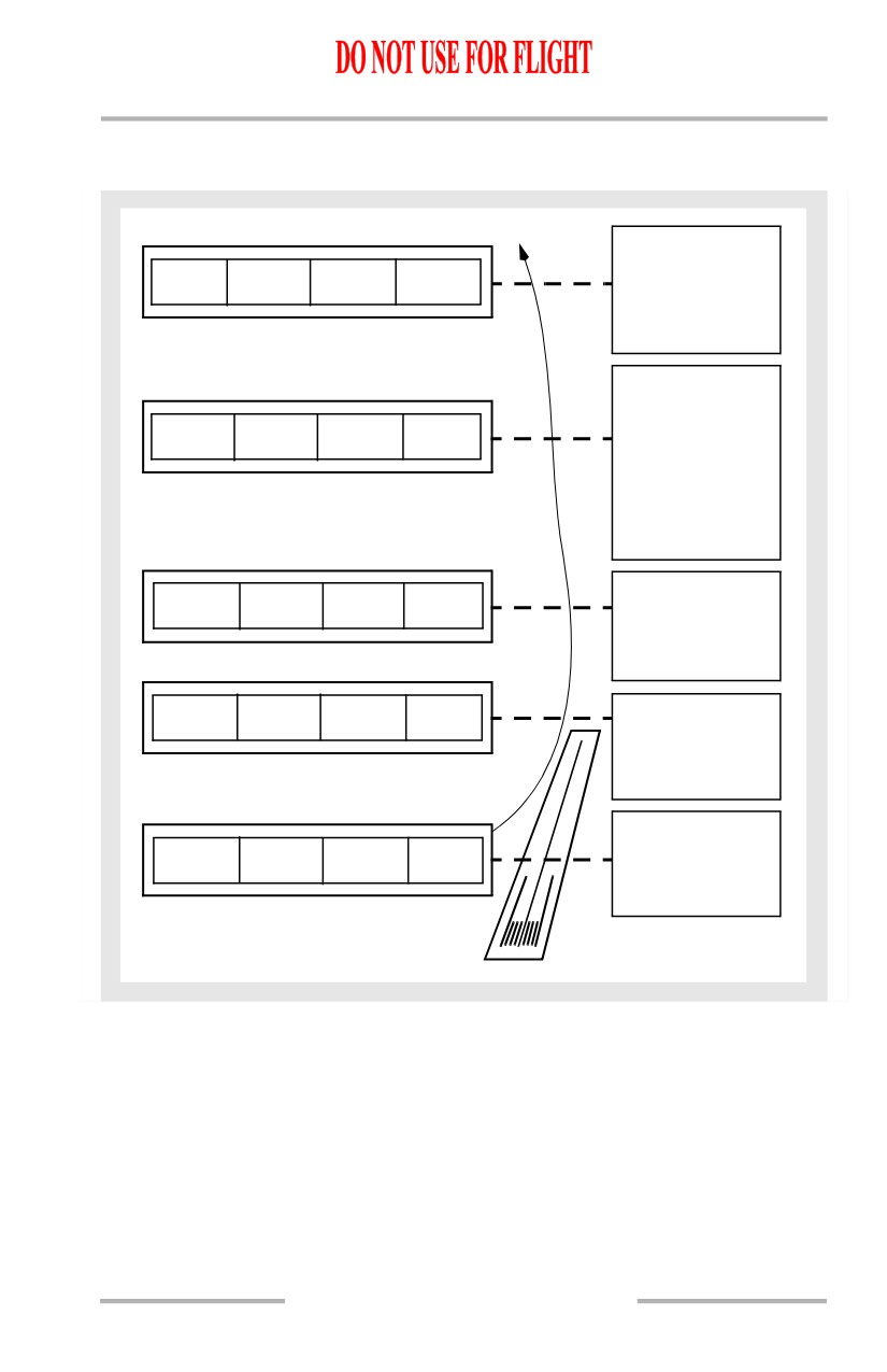
Automatic Flight Go-Around Profile
[Option - EFIS/MAP]
Missed Approach
altitude
MCP SPD
ALT HLD
LNAV
CMD
• Pitch mode
engages in
ALT HLD
Approaching
Missed Approach
altitude -
MCP SPD
ALT ACQ
LNAV
CMD
• Pitch mode
engages in
ALT ACQ
• A/T engages
in MCP SPD
Flap retract
GA
TO/GA
LNAV
CMD
altitude
• Retract flaps
on schedule
Above 400 feet
GA
TO/GA
LNAV
CMD
RA
• Select roll
mode
Push TO/GA
switches
GA
TO/GA
CMD
• A/T engages
in G/A
4.20.23
Automatic Flight -
System Description
Boeing 737 Operations Manual
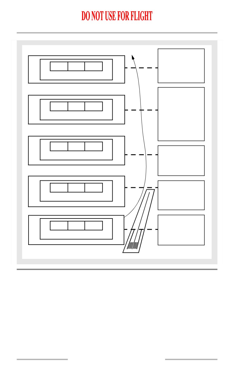
[Option - PFD/ND]
Missed Approach
altitude
MCP SPD
LNAV
ALT HLD
• Pitch mode
engages in
CMD
ALT HLD
Approaching
Missed Approach
MCP SPD
LNAV
ALT ACQ
altitude -
• Pitch mode
CMD
engages in
ALT ACQ
• A/T engages
in MCP SPD
GA
LNAV
TO/GA
Flap retract
CMD
altitude
• Retract flaps
on schedule
GA
LNAV
TO/GA
Above 400 feet
RA
CMD
• Select roll
mode
Push TO/GA
GA
TO/GA
switches
CMD
• A/T engages
in G/A
AFS Operation in Windshear
General
The autopilot and flight director provide positive corrective action to counteract
most windshears. The autothrottle system also aids in windshear recovery by
providing quick response to any increase or decrease in speed. The commanded
levels of power may be beyond what the average pilot considers necessary but, in
fact, are required by the situation.
4.20.24
Automatic Flight -
System Description
Boeing 737 Operations Manual
Takeoff or Go-Around
If windshear is encountered during F/D takeoff or go-around, the F/D pitch
command bar provides commands to maintain V2 + 20 kts until vertical speed
decreases to approximately +600 fpm. At this point, the F/D pitch bar commands
a 15 degree nose-up pitch attitude. If vertical speed continues to decrease, the F/D
continues to command a 15 degree pitch attitude until a speed of approximately
stick shaker is reached. It then commands pitch attitudes which result in
intermittent activation of the stick shaker. As the airplane transits the windshear
condition, the F/D programming reverses. As climb rate increases above
approximately +600 fpm, the F/D commands pitch attitudes which result in
acceleration back to V2 + 20 kts. The A/P and F/D both operate in a similar
manner during A/P or F/D go-around.
Approach and Landing
If windshear is encountered during an ILS approach, both the F/D and A/P attempt
to hold the airplane on altitude, or on glideslope after glideslope capture, without
regard to angle of attack or stick shaker limitations. Airspeed could decrease
below stick shaker and into a stall if the pilot does not intervene by pushing the
TO/GA switch or disconnecting the A/P and flying manually.
WARNING: Although the F/D, A/P and A/T may be performing as
previously described, severe windshear may exceed the
performance capability of the system and/or the airplane. In
this situation, the flight crew must, if necessary to avoid
ground contact, be prepared to disconnect the autothrottle,
advance thrust levers to the forward stop, disconnect the
autopilot and manually fly the airplane.
Command Speed Limiting and Reversion Modes
AFS command limiting and reversion operation is independent of the stall
warning and mach warning systems.
Command Speed Limiting
The AFS provides speed, pitch and thrust commands to avoid exceeding the
following limit speeds:
• Vmo/Mmo
• wing flap placards
• landing gear placard
• minimum speed.
The commanded speed can be equal to, but does not exceed a limit speed.
4.20.25
Automatic Flight -
System Description
Boeing 737 Operations Manual
Speeds greater than Vmo/Mmo cannot be selected from the MCP. Speeds can be
selected which exceed flap and gear placards or are less than minimum speed.
Minimum speed is based on angle of attack and is approximately 1.3 Vs for the
current flap configuration. It is sensed by the angle of attack vanes, one on either
side of the forward fuselage.
If a speed greater than a placard speed, or less than minimum speed is selected, the
AFS allows acceleration or deceleration to slightly short of the limit, then
commands the limit speed. The overspeed or underspeed limiting symbol appears
in the MCP IAS/Mach display when the commanded speed cannot be reached.
Either pitch or thrust, whichever is engaged in a speed mode, attempts to hold the
limit speed. The commanded limit speed and MCP speed condition symbol,
remain until another speed is selected which does not exceed the limit. A speed 15
knots greater than the minimum speed must be selected to remove the underspeed
limiting symbol.
Reversion Modes
During some flight situations, speed control by the AFDS or A/T alone could be
insufficient to prevent exceeding a limit speed. If this occurs, AFDS or A/T modes
automatically revert to a more effective combination. The reversion modes are:
• placard limit reversion
• minimum airspeed reversion.
Mode reversion occurs slightly before reaching the limit speed. Both the AFDS
and A/T have reversion modes which activate according to the condition causing
the reversion.
Placard Limit Reversion
When one of the placard limit reversions (gear, flap or Vmo/Mmo) is reached, the
overspeed limiting symbol appears in the MCP IAS/Mach display and the
following occurs:
• if not in AFDS or A/T speed control and the A/T is armed, the A/T reverts
to SPEED and controls speed to the placard limit
• if in AFDS or A/T speed control, no reversion is necessary. The AFDS or
A/T, whichever is controlling speed, holds speed slightly below the
placard limit
• if the A/T is not available, no reversion response to gear or flap placard
speeds is available. The AFDS reverts to speed control for Vmo/Mmo
speed limiting.
4.20.26
Automatic Flight -
System Description
Boeing 737 Operations Manual
Minimum Speed Reversion
The AFDS and A/T do not control to a speed which is less than minimum speed
for the current flap configuration. This speed is approximately 1.3 Vs. Minimum
speed, FMC speed, or selected speed, whichever is higher, becomes the AFS
commanded speed. If actual speed becomes equal to or slightly less than the
minimum speed, the underspeed limiting symbol appears in the MCP IAS/Mach
Display, and if operating in the V/S mode, the AFDS reverts to LVL CHG. The
AFDS will also revert to LVL CHG from VNAV PTH, except when flying a level
segment.
The AFS commands a speed 5 knots greater than minimum speed. Reaching a
speed 5 knots greater than minimum speed reactivates normal MCP speed
selection control. The AFDS commands nose down pitch to increase airspeed if
the thrust levers are not advanced. When actual speed becomes 5 knots greater
than minimum speed, the underspeed limiting symbol disappears.
The A/P disengages and the F/D command bars retract when in a LVL CHG climb
with a command speed equal to minimum speed and a minimum rate of climb
cannot be maintained without decelerating.
Minimum speed reversion is not available when the A/T is OFF and the AFDS is
in ALT HOLD or after G/S capture. Minimum speed reversion is also not
available when in VNAV PTH and flying a level segment.
4.20.27