Boeing 737 - 600/700/800/900. Operations Manual (1997 year) - page 29
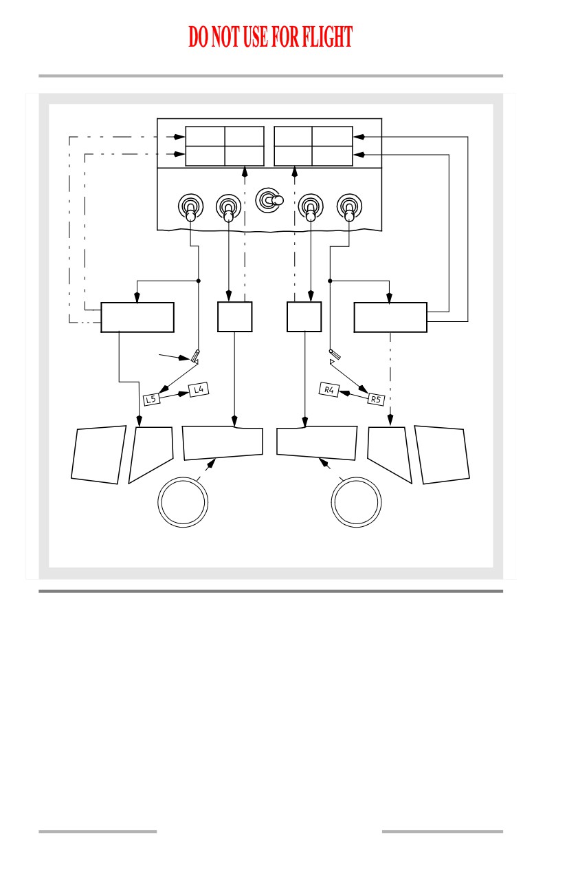
Anti-Ice, Rain -
System Description
Boeing 737 Operations Manual
[Option -Window # 3 not heated and amber OFF lights]
OVERHEAT
OFF
L
WINDOW HEAT
R
OVHT
SIDE
FWD
FWD
SIDE
OFF
OFF
ON
PWR TEST
ON
TEMPERATURE
TEMP
TEMP
TEMPERATURE
CONTROLLER
CONT
CONT
CONTROLLER
THERMAL
SWITCH
L1
R1
L3
L2
R2
R3
WIND
FROM
WIND
AIR CONDITIONING
SHIELD
SHIELD
SYSTEM
AIR
AIR
CONDITION:
WINDOW HEAT ON
R SIDE OVERHEATED
Windshield Wipers
The rain removal system for the forward windows consists of windshield wipers
and a permanent rain repellent coating on the windows. The forward windows are
equipped with independently controlled wipers.
CAUTION: Windshield scratching will occur if the windshield wipers are
operated on a dry windshield.
3.20.4
Anti-Ice, Rain -
System Description
Boeing 737 Operations Manual
Probe and Sensor Heat
[Option - Captain’s pitot probe on standby power]
Pitot probes, the total air temperature probe and the alpha vanes are electrically
heated. Static ports are not heated. When operating on standby power, only the
captain’s pitot probe is heated, however, the CAPT PITOT light does not
illuminate for a failure.
Note: The pitot probe for standby airspeed is not heated when the airplane is on
standby power.
Ice Detection System
[Option]
An advisory only ice detection system detects airplane icing in flight. The system
consists of a probe located on the forward left fuselage and advisory lights located
on the left forward panel.
When the probe senses ice build-up inflight, the ICING light illuminates. When
ice has previously been detected and the probe is no longer detecting ice, the
ICING light will extinguish and the NO ICE light will illuminate. The ICING light
and the NO ICE light do not illuminate simultaneously.
Note: Residual ice may remain on the window areas with the NO ICE light
illuminated.
The ICE DETECTOR light, located on the forward overhead panel, will
illuminate if the ice detection system fails. Illumination of the ICE DETECTOR
light also illuminates the MASTER CAUTION and ANTI-ICE system
annunciator lights.
Engine Anti-Ice System
Engine bleed air thermal anti-icing prevents the formation of ice on the engine
cowl lip. Engine anti-ice operation is controlled by individual ENG ANTI-ICE
switches. The engine anti-ice system may be operated on the ground and in flight.
3.20.5
Anti-Ice, Rain -
System Description
Boeing 737 Operations Manual
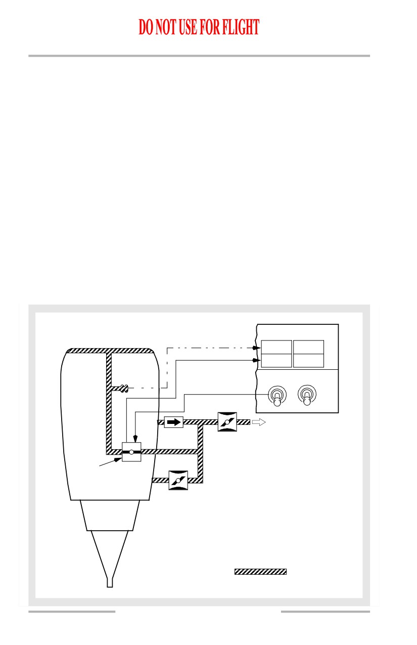
Engine Anti-Ice System Operation
Each cowl anti-ice valve is electrically controlled and pressure actuated.
Positioning the ENG ANTI-ICE switches to ON:
• allows engine bleed air to flow through the cowl anti-ice valve for cowl
lip anti-icing
• sets stick shaker logic for icing conditions.
Note: Adjusts stick shaker and minimum maneuver speed bars on airspeed
indications. FMC displayed VREF is not adjusted automatically.
Note: Stick shaker logic and airspeed indications return to normal when
engine anti-ice is positioned OFF if wing anti-ice has not been used in
flight.
If the cowl anti-ice valve fails to move to the position indicated by the ENG
ANTI-ICE switch, the COWL VALVE OPEN light remains illuminated bright
blue and an amber TAI indication illuminates on the CDS after a short delay.
The amber COWL ANTI-ICE light illuminates due to excessive pressure in the
duct leading from the cowl anti-ice valve to the cowl lip.
Engine Anti-Ice System Schematic
ENGINE COWL
ANTI-ICE (TAI)
COWL
COWL
ANTI-ICE
ANTI-ICE
COWL VALVE
COWL VALVE
OPEN
OPEN
ENG
ANTI-ICE
OFF
ON
1
2
5th
TO
BLEED AIR
ENGINE
DUCT
BLEED
VALVE
COWL
ANTI-ICE
VALVE
9th
MODULATING &
SHUTOFF VALVE
BLEED AIR
3.20.6
Anti-Ice, Rain -
System Description
Boeing 737 Operations Manual
Wing Anti-Ice System
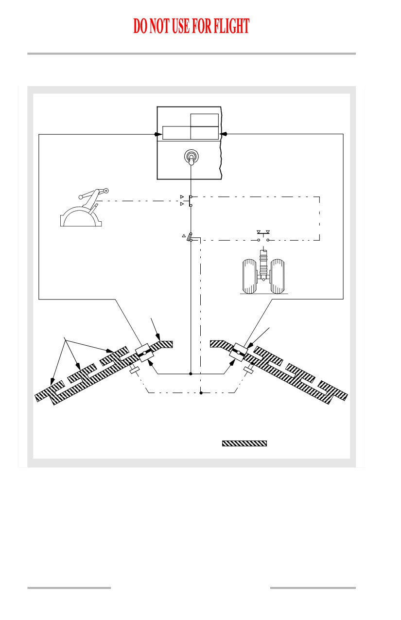
The wing anti-ice system provides protection for the three inboard leading edge
slats by using bleed air. The wing anti-ice system does not include the leading
edge flaps or the outboard leading edge slats.
The wing anti-ice control valves are AC motor-operated. With a valve open,
bleed air flows to the three leading edge inboard slats, and is then exhausted
overboard. The wing anti-ice system is effective with the slats in any position.
Wing Anti-Ice System Operation
On the ground, positioning the WING ANTI-ICE switch ON opens both control
valves if thrust on both engines is below the setting for takeoff warning activation
and the temperature inside both wing distribution ducts is less than the thermal
switch activation temperature.
Both valves close if either engine thrust is above the takeoff warning setting or
either temperature sensor senses a duct overtemperature. The valves automatically
reopen if thrust on both engines is reduced and both temperature sensors are cool.
With the air/ground sensor in the ground mode and the WING ANTI-ICE switch
ON, the switch remains in the ON position regardless of control valve position.
The WING ANTI-ICE switch automatically trips OFF at lift-off when the
air/ground sensor goes to the air mode.
Positioning the WING ANTI-ICE switch to ON in flight:
• opens both control valves
• sets stick shaker logic for icing conditions.
Note: Adjusts stick shaker and minimum maneuver speed bars on airspeed
indications. FMC displayed VREF is not adjusted automatically.
Note: Stick shaker logic remains set for icing conditions for the remainder of
the flight, regardless of subsequent WING ANTI-ICE switch position.
Valve position is monitored by the blue VALVE OPEN lights. Duct temperature
and thrust setting logic are disabled and have no affect on control valve operation
in flight.
October 15, 2001
3.20.7
Anti-Ice, Rain -
System Description
Boeing 737 Operations Manual
Wing Anti-Ice System Schematic
[Option - ICE DETECTOR light]
ICE
DETECTOR
L VALVE
R VALVE
OPEN
OPEN
WING ANTI-ICE
OFF
ON
THRUST
LEVERS
ABOVE T.O.
WARNING
BELOW T.O.
WARNING
HIGH
THERMAL SWITCH
GROUND
TEMP
LOW
AIR
TEMP
RIGHT MAIN
LANDING GEAR
BLEED
AIR DUCT
WING ANTI-ICE
LEADING EDGE SLATS
CONTROL VALVE
CONDITION:
ON THE GROUND
WING ANTI-ICE ON
ENGINES AT IDLE THRUST
DUCT TEMPS LOW
BLEED AIR
3.20.8
Boeing 737 Operations Manual
Automatic Flight
Chapter 4
Table of Contents
Section 0
4.0 Automatic Flight-Table of Contents
Controls and Indicators
4.10.1
Mode Control Panel (MCP)
4.10.1
Speed Controls
4.10.1
Vertical Navigation
4.10.5
Lateral Navigation
4.10.11
Autopilot / Flight Director
4.10.16
Autopilot / Autothrottle Controls
4.10.19
Autopilot / Autothrottle Indicators
4.10.20
Autoland Warning
4.10.21
Thrust Mode Display
4.10.22
Flight Mode Annunciations (FMAs)
4.10.24
System Description
4.20.1
General
4.20.1
Autopilot Flight Director System (AFDS)
4.20.1
MCP Mode Selector Switches
4.20.1
Autopilot Engagement Criteria
4.20.2
Autopilot Disengagement
4.20.2
AFS Failures
4.20.2
Flight Director Display
4.20.3
AFDS Status Annunciation
4.20.4
AFDS Flight Mode Annunciations
4.20.4
Autopilot Control Wheel Steering
4.20.7
Autothrottle System
4.20.8
A/T Engagement
4.20.8
Autothrottle Disengagement
4.20.8
Automatic Flight Operations
4.20.9
Automatic Flight Takeoff and Climb
4.20.9
Automatic Flight Takeoff Profile
4.20.12
Automatic Flight En Route
4.20.13
4.TOC.0.1
Automatic Flight -
Table of Contents
Boeing 737 Operations Manual
Automatic Flight Approach and Landing
4.20.14
Automatic Flight Approach Profile
4.20.17
Go-Around
4.20.19
Automatic Flight Go-Around Profile
4.20.23
AFS Operation in Windshear
4.20.24
General
4.20.24
Takeoff or Go-Around
4.20.25
Approach and Landing
4.20.25
Command Speed Limiting and Reversion Modes
4.20.25
Command Speed Limiting
4.20.25
Reversion Modes
4.20.26
4.TOC.0.2
Boeing 737 Operations Manual
Automatic Flight
Chapter 4
Controls and Indicators
Section 10
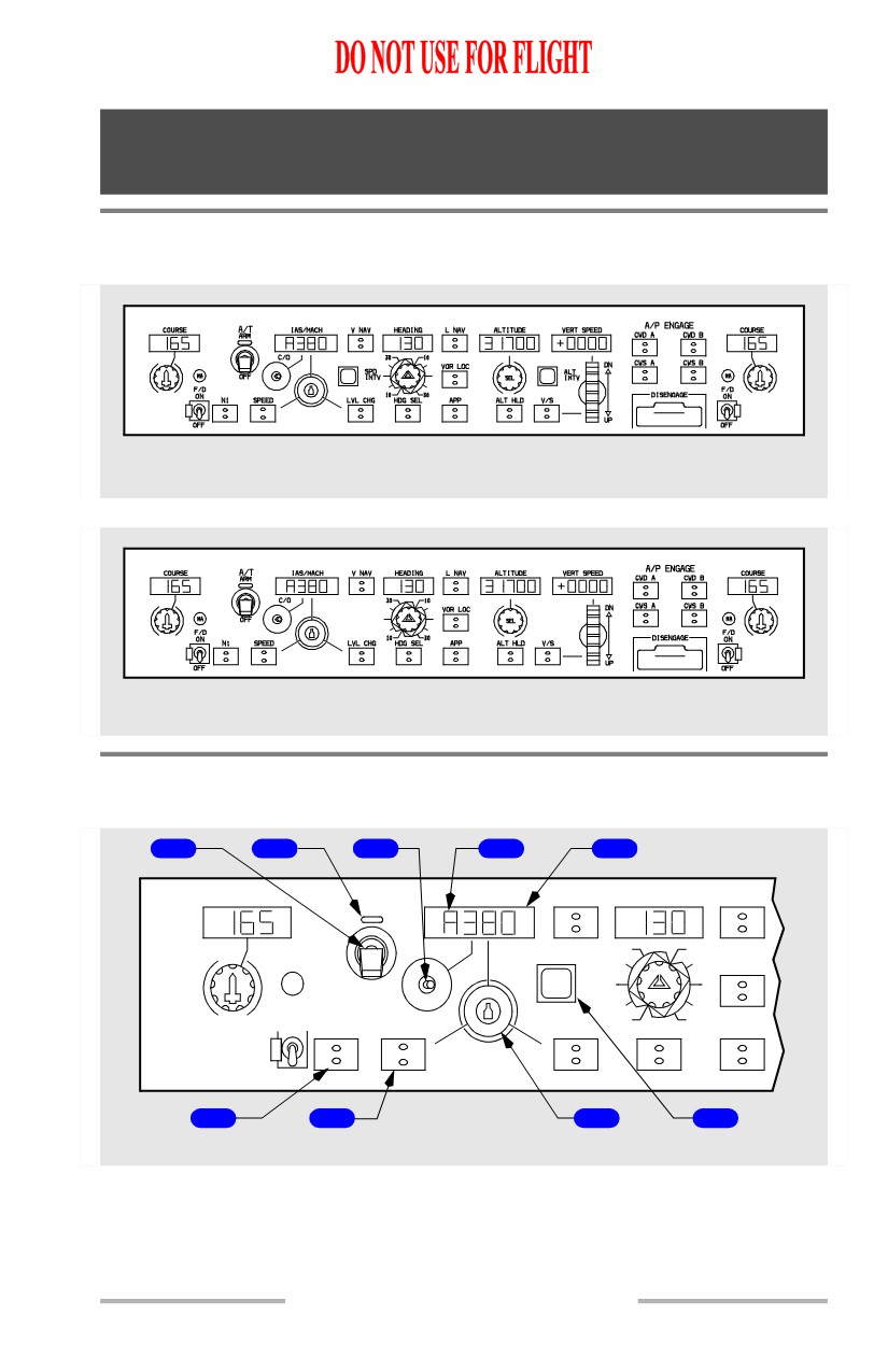
Mode Control Panel (MCP)
[Option - With speed and altitude intervention]
GLARESHIELD
[Option - Without speed and altitude intervention]
GLARESHIELD
Speed Controls
[Option - With speed and altitude intervention]
1
2
3
4
5
A/T
IAS/MACH
V NAV
HEADING
L NAV
COURSE
ARM
C/O
30
10
VOR LOC
SPD
MA
OFF
INTV
F/D
10
30
ON
N1
SPEED
LVL CHG
HDG SEL
APP
OFF
6
7
8
9
GLARESHIELD
4.10.1
Automatic Flight -
Controls and Indicators
Boeing 737 Operations Manual
[Option - Without speed and altitude intervention]
1
2
3
4
5
A/T
IAS/MACH
V NAV
HEADING
L NAV
COURSE
ARM
C/O
30
10
VOR LOC
MA
OFF
F/D
10
30
ON
N1
SPEED
LVL CHG
HDG SEL
APP
OFF
6
7
8
GLARESHIELD
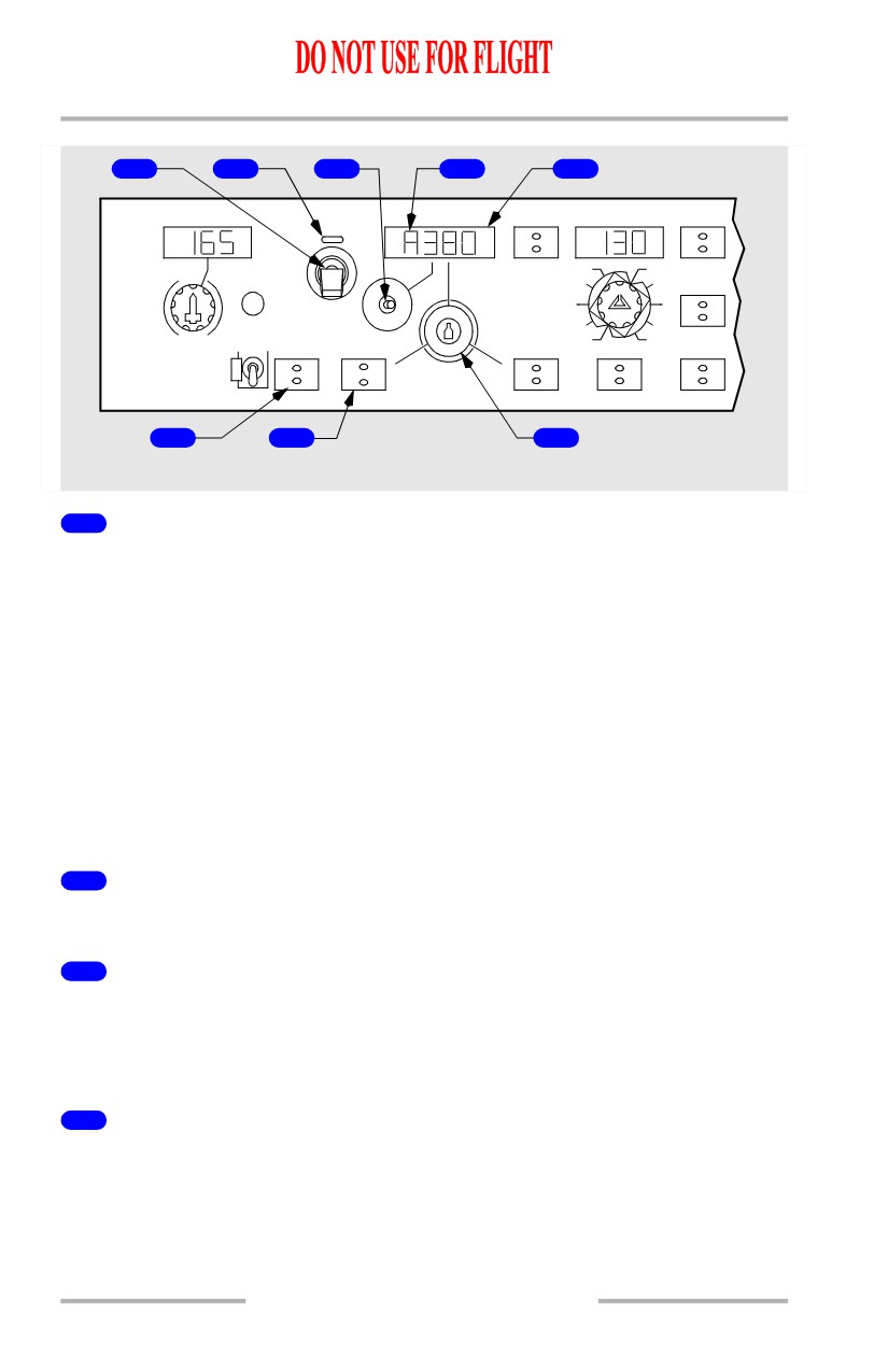
1
Autothrottle (A/T) Arm Switch
ARM - Arms A/T for engagement. Magnetically held at ARM. A/T engages
automatically when following AFDS modes are engaged:
• LVL CHG
• ALT ACQ
• V/S
• VNAV
• ALT HOLD
• G/S capture
• TO/GA.
OFF - disengages A/T and prevents A/T engagement.
2
Autothrottle Indicator Light
Illuminated (green) - A/T ARM switch in ARM position.
3
Changeover (C/O) Switch
Push -
• changes IAS/MACH display between IAS and MACH
• automatic changeover occurs at approximately FL260.
4
MCP Speed Condition Symbols
Overspeed or underspeed limiting symbol appears when
commanded speed
cannot be reached.
Underspeed limiting (flashing character “A”) - minimum speed
4.10.2
Automatic Flight -
Controls and Indicators
Boeing 737 Operations Manual
Overspeed limiting (flashing character “8”) -
• Vmo or Mmo limit
• landing gear limit
• flap limit.
5
IAS/MACH Display
Displays speed selected by IAS/MACH selector
• display is blank when:
• VNAV mode engaged
• A/T engaged in FMC SPD mode
• during 2 engine AFDS go-around
• displays 100 knots when power is first applied
• display range is:
•
100 KIAS - Vmo in 1 knot increments
•
.60M - Mmo in .01M increments.
6
N1 Switch
Push - (light not illuminated)
• engages A/T in N1 mode if compatible with AFDS modes already
engaged
• illuminates N1 switch light
• annunciates N1 autothrottle mode.
Push - (light illuminated)
• deselects N1 mode and extinguishes switch light
• engages autothrottles in ARM mode.
N1 Mode
• A/T maintains thrust at N1 limit selected from FMC CDU. N1 mode
engaged manually by pushing N1 switch if N1 mode is compatible with
existing AFDS modes. N1 mode engages automatically when:
• engaging LVL CHG in climb (except during inhibit period for 2 1/2
minutes after lift-off)
• engaging VNAV in climb.
7
SPEED Switch
Push - (light not illuminated)
• engages A/T in SPEED mode if compatible with engaged AFDS modes
• illuminates SPEED switch light
• annunciates MCP SPD autothrottle mode
• maintains speed in MCP IAS/MACH display.
4.10.3
Automatic Flight -
Controls and Indicators
Boeing 737 Operations Manual
Push - (light illuminated)
• deselects speed mode and extinguishes switch light
• engages A/T in ARM mode.
Speed Mode
Autothrottle holds speed in IAS/MACH display or a performance or limit speed.
Speed mode engaged manually by pushing SPEED switch if speed mode is
compatible with existing AFDS modes. Speed mode engages automatically when:
• ALT ACQ engages
• ALT HOLD engages
• V/S engages
• G/S capture occurs.
A/T does not set thrust above displayed N1 limit, however, A/T can exceed N1
value manually set by N1 Manual Set Knob.
8
IAS/MACH Selector
Rotate -
• sets speed in IAS/MACH display and positions airspeed cursor
• selected speed is reference speed for AFDS and A/T
• not operative when IAS/MACH display is blank.
9
Speed Intervention (SPD INTV) Switch
[Option - With speed and altitude intervention]
Push (when VNAV engaged) -
• IAS/MACH display alternately shows selected IAS/Mach and blanks
• when IAS/MACH display is unblanked, FMC speed intervention is
active, FMC target speed is displayed, and IAS/MACH Selector may be
used to set desired speed
• when IAS/MACH display is blank, FMC computed target speed is active
and displayed on the airspeed indicator.
4.10.4
Automatic Flight -
Controls and Indicators
Boeing 737 Operations Manual
Vertical Navigation
[Option - With speed and altitude intervention]
1
2
3
4
V NAV
HEADING
L NAV
ALTITUDE
VERT SPEED
30
10
VOR LOC
DN
ALT
SEL
INTV
10
30
LVL CHG
HDG SEL
APP
ALT HLD
V/S
UP
5
6
7
8
9
10
GLARESHIELD
[Option - Without speed and altitude intervention]
1
2
3
4
V NAV
HEADING
L NAV
ALTITUDE
VERT SPEED
30
10
VOR LOC
DN
SEL
10
30
LVL CHG
HDG SEL
APP
ALT HLD
V/S
UP
5
6
7
8
9
GLARESHIELD
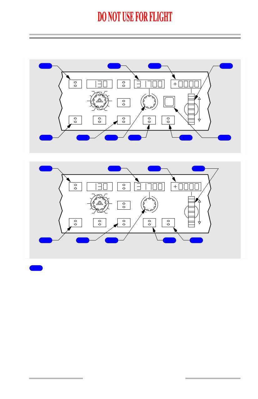
1
VNAV Switch
Push -
• VNAV switch light illuminates
• pitch mode annunciates VNAV SPD, VNAV PTH
• A/T mode annunciates FMC SPD, N1, RETARD, or ARM
• IAS/MACH display blanks and airspeed cursors positioned to FMC
commanded airspeed.
VNAV Mode
4.10.5
Automatic Flight -
Controls and Indicators
Boeing 737 Operations Manual
The FMC commands AFDS pitch and autothrottle to fly vertical profile selected
on FMC CDUs. Profile includes climb, cruise, descent, speeds, and can also
include waypoint altitude constraints.
Note: If the airplane is between the FMC target altitude (depicted on the RTE
LEGS page for the active waypoint) and the manually entered MCP target
altitude, VNAV will not engage. To enable VNAV, adjust the FMC or MCP
target altitude as appropriate.
Climb -
• autothrottle holds FMC thrust limit
• AFDS holds FMC target speed
• automatic level-off occurs at MCP altitude or VNAV altitude, whichever
is reached first
• VNAV constrained level-off annunciates VNAV PTH.
Cruise -
• autothrottle holds FMC target speed
• AFDS holds FMC altitude
• selecting a lower MCP altitude arms FMC to automatically begin descent
upon arrival at FMC top of descent point.
Descent -
• VNAV SPD descent
• autothrottle holds idle
• AFDS holds FMC target speed.
• VNAV PTH descent
• autothrottle holds idle but can command FMC SPD mode if ground
speed becomes too low to maintain FMC vertical path
• AFDS tracks FMC descent path.
• automatic level-off occurs at MCP altitude or VNAV altitude, whichever
is reached first
• VNAV constrained altitude annunciates VNAV PTH.
Inhibited below 400 ft RA or if performance initialization not complete.
VNAV mode is terminated by any one of the following:
• selecting another pitch mode
• glideslope capture
• reaching end of LNAV route
[Option - FMC update 10.3 and later]
• transition of glideslope intercept waypoint if G/S is armed
4.10.6
Automatic Flight -
Controls and Indicators
Boeing 737 Operations Manual
[Option - FMC update 10.3 and later]
• crosstrack deviation exceeds twice the RNP value during PTH descent for
an active leg with a database vertical angle and LNAV not engaged
• if the airplane altitude is more than 200 feet below MCP altitude and the
autoflight system is not in altitude acquire.
In the event of glideslope intercept waypoint transition, VNAV can be re-engaged.
When the pitch mode changes from VNAV SPD to ALT ACQ during an
intermediate level off, the autothrottle will command a target IAS rather than
Mach number. This is valid even at altitudes above the IAS/Mach changeover. If
the climb is resumed in LVL CHG or V/S, the airspeed window opens at the target
IAS which may result in an overspeed condition.
2
ALTITUDE Display
Displays selected altitude
• displayed altitude is reference for altitude alerting and automatic
level-offs
• altitude range is 0 to 50,000 feet in 100 foot increments
• displays previously selected altitude when power first applied.
3
Vertical Speed (VERT SPEED) Display
Displays:
• blank when V/S mode not active
• present V/S when V/S mode is engaged with V/S switch
• selected V/S when V/S set with thumbwheel
• range is -7900 to +6000 fpm.
Display increments are:
•
50 fpm if V/S is less than 1000 fpm
•
100 fpm if V/S is 1000 fpm or greater.
4
Vertical Speed Thumbwheel
Rotate -
• DN -
• sets vertical speed in VERT SPEED display
• increases rate of descent or reduces rate of ascent.
• UP -
• sets vertical speed in VERT SPEED display
• increases rate of ascent or reduces rate of descent.
4.10.7
Automatic Flight -
Controls and Indicators
Boeing 737 Operations Manual
5
Level Change (LVL CHG) Switch
Push -
• LVL CHG switch light illuminates
• pitch mode annunciates MCP SPD for climb or descent
• autothrottle mode annunciates N1 for climb and RETARD followed by
ARM for descent
• IAS/MACH display and airspeed cursors display target speed.
LVL CHG Mode
The LVL CHG mode coordinates pitch and thrust commands to make automatic
climbs and descents to preselected altitudes at selected airspeeds.
A LVL CHG climb or descent is initiated by:
• selecting a new altitude
• pushing LVL CHG switch
• setting desired airspeed.
Climb -
• autothrottle holds limit thrust
• AFDS holds selected airspeed.
Descent -
• autothrottle holds idle thrust
• AFDS holds selected airspeed.
Airspeed -
• if a speed mode is active when LVL CHG is engaged, this speed is
retained as target speed
• if a speed mode is not active when LVL CHG is engaged, existing speed
becomes target speed
• speed can be changed with MCP IAS/MACH Selector.
The LVL CHG mode is inhibited after glideslope capture.
6
Approach (APP) Switch
(See Lateral Navigation)
7
Altitude Selector (SEL)
Rotate -
• sets altitude in ALTITUDE display in 100 foot increments
• arms V/S mode if rotated while in ALT HOLD at selected altitude.
4.10.8
Automatic Flight -
Controls and Indicators
Boeing 737 Operations Manual
8
Altitude Hold (ALT HLD) Switch
Push -
• engages ALT HOLD command mode
• commands pitch to hold uncorrected barometric altitude at which switch
was pressed
• annunciates ALT HOLD pitch mode and illuminates ALT HLD switch
light.
Altitude Hold Command Mode
ALT HOLD mode commands pitch to hold either:
• MCP selected altitude
• pitch mode annunciates ALT HOLD
• ALT HLD switch light extinguishes.
• uncorrected barometric altitude at which ALT HLD switch was pressed if
not at MCP selected altitude
• pitch mode annunciates ALT HOLD
• ALT HLD switch light illuminates.
When in ALT HOLD at selected MCP altitude:
• selecting a new MCP altitude illuminates the ALT HLD switch light and
arms V/S mode
• LVL CHG, V/S, and VNAV climb and descent functions are inhibited
until a new MCP altitude is selected.
ALT HOLD mode is inhibited after G/S capture.
The selected MCP altitude is referenced to:
• Captain’s barometric altimeter setting for A A/P and F/D
• First Officer’s barometric altimeter setting for B A/P and F/D.
Note: After ALT HOLD engages, changes in altimeter barometric settings do not
change the selected altitude reference.
9
Vertical Speed (V/S) Switch
Push -
• arms or engages V/S command mode
• commands pitch to hold vertical speed
• engages A/T in speed mode to hold selected airspeed
• annunciates V/S pitch mode and illuminates V/S switch light.
Vertical Speed Command Mode
The V/S mode commands pitch to hold selected vertical speed and engages A/T
in SPEED mode to hold selected airspeed. V/S mode has both an armed and an
engaged state.
4.10.9
Automatic Flight -
Controls and Indicators
Boeing 737 Operations Manual
Engaged -
• annunciates V/S pitch mode
• vertical speed display changes from blank to present vertical speed
• desired vertical speeds can be selected with vertical speed thumbwheel.
V/S becomes armed if:
• pitch mode is ALT HLD at selected MCP altitude and
• new MCP altitude is selected (more than 100 feet from current altitude).
With V/S armed, V/S mode is engaged by moving vertical speed thumbwheel.
V/S mode automatically engages if ALT ACQ mode is engaged and a new MCP
altitude is selected which is more than 100 feet different from previously selected
altitude.
• vertical speeds can be selected which command flight toward or away
from selected altitude.
Inhibited if:
• ALT HOLD mode is active at selected MCP altitude
• glideslope captured in APP mode.
10
Altitude Intervention (ALT INTV) Switch
[Option - With speed and altitude intervention]
Allows manual deletion of next FMC altitude constraint via altitude SEL and ALT
INTV switch.
Push - (during VNAV climb)
• lowest FMC altitude constraint below selected MCP altitude is deleted
• if airplane is currently at an FMC altitude constraint, deletion allows
airplane to resume climb. MCP altitude must be set above current altitude
• for each press of switch, one deletion occurs
• if MCP altitude is set above current FMC altitude, FMC cruise altitude
resets to MCP altitude. FMC cruise altitude cannot be decreased using
ALT INTV switch.
Push - (during VNAV cruise)
• if MCP altitude is set above current FMC cruise altitude, FMC resets
cruise altitude to MCP altitude and initiates a cruise climb
• if MCP altitude is set below current FMC cruise altitude, an early descent
is initiated. Lower FMC cruise altitude cannot be entered using ALT
INTV switch.
4.10.10
Automatic Flight -
Controls and Indicators
Boeing 737 Operations Manual
Push - (during VNAV descent)
• the highest FMC altitude constraint above MCP altitude is deleted
• if airplane is currently at an FMC altitude constraint, deletion allows
airplane to continue descent. MCP altitude must be set below current
altitude
• if all FMC altitude constraints are deleted during VNAV path descent, an
automatic transition to a VNAV speed descent is made.
Lateral Navigation
[Option - With speed and altitude intervention]
1
2
3
4
5
A/T
IAS/MACH
V NAV
HEADING
L NAV
COURSE
ARM
C/O
30
10
VOR LOC
SPD
MA
OFF
INTV
F/D
10
30
ON
N1
SPEED
LVL CHG
HDG SEL
APP
OFF
6
7
8
9
GLARESHIELD
[Option - Without speed and altitude intervention]
1
2
3
4
5
COURSE
A/T
IAS/MACH
V NAV
HEADING
L NAV
ARM
C/O
30
10
VOR LOC
MA
OFF
F/D
10
30
ON
N1
SPEED
LVL CHG
HDG SEL
APP
OFF
6
7
8
9
GLARESHIELD
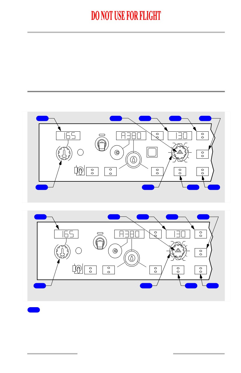
1
COURSE Display
Displays course set by course selector.
Note: Different courses and frequencies on two VHF NAV receivers can cause
disagreement between Captain and FO F/D displays and affect A/P
operation.
4.10.11
Automatic Flight -
Controls and Indicators
Boeing 737 Operations Manual
2
Heading Selector
Rotate -
• sets heading in HEADING display
• positions selected heading bugs on the DUs.
3
HEADING Display
Displays selected heading.
4
LNAV Switch
Push -
• commands AFDS roll to intercept and track the active FMC route
• annunciates LNAV as roll mode and illuminates LNAV switch light.
LNAV Mode
In LNAV mode, the FMC controls AFDS roll to intercept and track active FMC
route. Active route is entered and modified through FMC CDUs and can include
SIDs, STARs, and instrument approaches.
LNAV engagement criteria on the ground:
• origin runway in flight plan
• active route entered in FMC
• track of first leg within 5 degrees of runway heading
• LNAV selected prior to TO/GA. Once TO/GA is engaged, the LNAV
switch light is extinguished until 400 feet AGL
• LNAV guidance becomes active at 50 feet AGL
[Option - Bank angle limit is 30 degrees above 200 AGL]
[Option - Honeywell FCC -708 or -904 or -905]
• bank angle is limited to 8 degrees below 200 feet and 30 degrees
above 200 feet AGL.
LNAV engagement criteria in flight:
• active route entered in FMC
• within 3 NM of active route, LNAV engagement occurs with any airplane
heading
• outside of 3 NM, airplane must:
• be on intercept course of 90 degrees or less
• intercept route segment before active waypoint.
LNAV automatically disconnects for following reasons:
• reaching end of active route
• reaching a route discontinuity
• intercepting a selected approach course in VOR LOC or APP modes
(VOR/LOC armed)
4.10.12
Automatic Flight -
Controls and Indicators
Boeing 737 Operations Manual
• selecting HDG SEL
• loss of capture criteria.
5
VOR Localizer (LOC) Switch
Push -
• commands AFDS roll to capture and track selected VOR or LOC course
• annunciates VOR/LOC armed or engaged as roll mode and illuminates
VOR LOC switch light.
VOR LOC Mode
Pushing the VOR LOC switch selects VOR mode if a VOR frequency is tuned or
selects LOC mode if a localizer frequency is tuned.
The VOR mode provides roll commands to track selected VOR course.
The LOC mode provides roll commands to track selected localizer course along
inbound front course bearing.
The selected course can be intercepted while engaged in:
• LNAV
• HDG SEL
• CWS R if an autopilot is engaged in CMD.
The capture point is variable and depends on intercept angle and closure rate.
Localizer capture occurs not later than 1/2 dot deviation. Course capture is
indicated when VOR/LOC annunciation changes from armed to engaged.
While engaged in VOR or LOC modes:
• A autopilot and Captain’s F/D use information from Captain’s course
selector and No. 1 VHF NAV receiver
• B autopilot and First Officer’s F/D use information from First Officer’s
course selector and No. 2 VHF NAV receiver
• different courses and/or frequencies for two VHF NAV receivers can
cause disagreement between the Captain’s and First Officer’s F/D
displays and affect A/P operation.
Note: When a localizer frequency is selected, VHF NAV radios automatically
switch from tail antenna to nose antenna when VOR/LOC is annunciated
(armed or engaged). If antenna switching does not occur, LOC mode is
inhibited.
Note: Localizer backcourse tracking is not available.
6
Course Selector
Sets course in COURSE display for related VHF NAV receiver, AFDS and DU.
Two course selectors and COURSE displays are located on the MCP.
4.10.13