Boeing 737 - 600/700/800/900. Operations Manual (1997 year) - page 28
Air Systems -
Pressurization System
Description
Boeing 737 Operations Manual
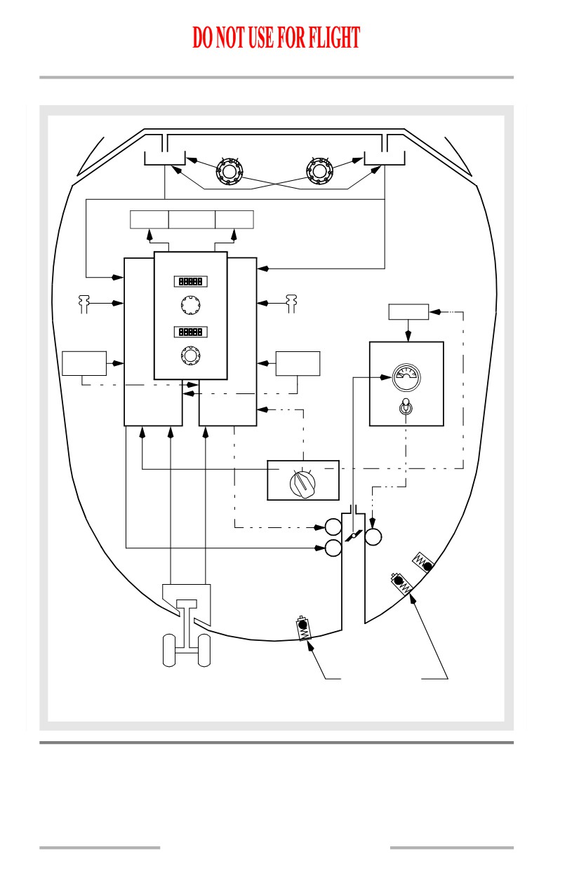
Cabin Pressure Control System Schematic
BARO
BARO
IN HPA
IN HPA
ADIRU
ADIRU
STD
STD
STATIC PORT
STATIC PORT
AUTO
OFF SCHED
ALTN
FAIL
DESCENT
AUTO
FLT ALT
MANUAL
CABIN
CABIN
SENSE
SENSE
PORT
LAND ALT
PORT
STALL
STALL
MANUAL
MANAGEMENT
MANAGEMENT
V
COMPUTER
COMPUTER
A
L
V
E
C
O
AUTO
AUTO
L
P
O
E
CONTROLLER
CONTROLLER
S
N
E
ALTN
AUTO
MAN
DC
DC
DC
NEGATIVE
PRESSURE
RELIEF
AIR/GROUND
SAFETY
OUTFLOW
SENSORS
VALVE
CONDITION:
PRESSURE RELIEF
IN FLIGHT
MAXIMUM 9.1 PSI
NORMAL OPERATION
Pressurization Outflow
Cabin air outflow is controlled by the outflow valve and the overboard exhaust
valve. A small amount is also exhausted through toilet and galley vents,
miscellaneous fixed vents, and by seal leakage.
2.40.2
Air Systems -
Pressurization System
Description
Boeing 737 Operations Manual
Outflow Valve
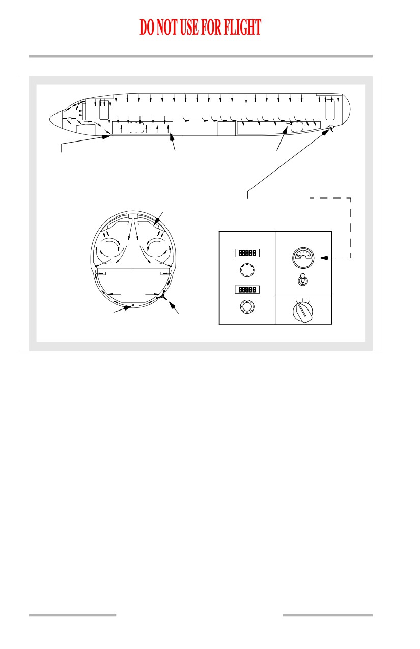
The outflow valve is the overboard exhaust exit for the majority of the air
circulated through the passenger cabin. Passenger cabin air is drawn through foot
level grills, down around the aft cargo compartment, where it provides heating,
and is discharged overboard through the outflow valve.
Overboard Exhaust Valve
On the ground and in flight with low differential pressure, the overboard exhaust
valve is open and warm air from the E & E bay is discharged overboard. In flight,
at higher cabin differential pressures, the overboard exhaust valve is normally
closed and exhaust air is diffused to the lining of the forward cargo compartment.
[737-600 or 737-700]
However, the overboard exhaust valve is driven open if either pack switch is in
high and the recirculation fan is off. This allows for increased ventilation in the
smoke removal configuration.
[737-800 or 737-900]
However, the overboard exhaust valve is driven open if either pack switch is in
high and the right recirculation fan is off. This allows for increased ventilation in
the smoke removal configuration.
2.40.3
Air Systems -
Pressurization System
Description
Boeing 737 Operations Manual
Pressurization Outflow Schematic
EXHAUST PORT FOR
FWD CARGO
AFT CARGO
OVERBOARD EXHAUST VALVE
COMPARTMENT
COMPARTMENT
- Exhausts E & E cooling air while
on ground, and in flight at low
differential pressure.
DIFFUSER, OVERHEAD
DIFFUSER
OUTFLOW VALVE
OUTLETS AND CARGO
OUTLET
- Controlled by the
COMPARTMENT
pressurization system.
AIRFLOW
AUTO
MANUAL
V
A
L
FLT ALT
V
E
C
O
L
P
CARGO COMPARTMENT
O
E
S
N
E
LINING
LAND ALT
ALTN
AUTO
MAN
EXHAUST PORT FOR
OUTFLOW
OVERBOARD EXHAUST VALVE
VALVE
AFT LOOKING FORWARD
2.40.4
Air Systems -
Pressurization System
Description
Boeing 737 Operations Manual
Auto Mode Operation
The AUTO system consists of two identical controllers, with one controller
alternately sequenced as the primary operational controller for each new flight.
The other automatic controller is immediately available as a backup.
In the AUTO or ALTN mode, the pressurization control panel is used to preset two
altitudes into the auto controllers:
• FLT ALT (flight or cruise altitude).
• LAND ALT (landing or destination airport altitude).
Takeoff airport altitude (actually cabin altitude) is fed into the auto controllers at
all times when on the ground.
The air/ground safety sensor signals whether the airplane is on the ground or in
the air. On the ground and at lower power settings, the cabin is depressurized by
driving the outflow valve to the full open position.
The cabin begins to pressurize on the ground at higher power settings. The
controller modulates the outflow valve toward close, slightly pressurizing the
cabin. This ground pressurization of the cabin makes the transition to pressurized
flight more gradual for the passengers and crew, and also gives the system better
response to ground effect pressure changes during takeoff.
In the air, the auto controller maintains a proportional pressure differential
between airplane and cabin altitude. By increasing the altitude at a rate
proportional to the airplane climb rate, cabin altitude change is held to the
minimum rate required.
An amber OFF SCHED DESCENT light illuminates if the airplane begins to
descend without having reached the preset cruise altitude; for example, a flight
aborted in climb and returning to the takeoff airport. The controller programs the
cabin to land at the takeoff field elevation without further pilot inputs. If the FLT
ALT indicator is changed, the automatic abort capability to the original takeoff
field elevation is lost.
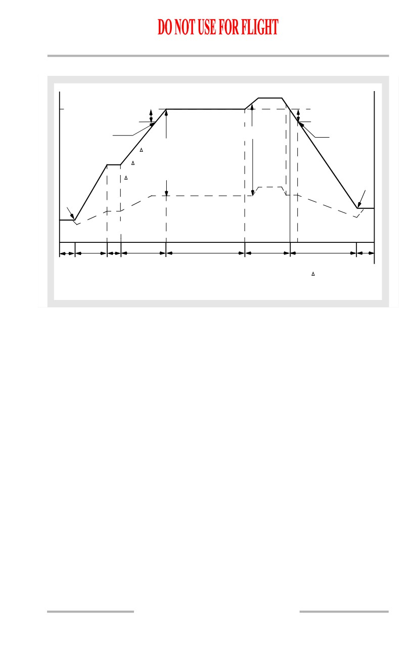
The cruise mode is activated when the airplane climbs to within 0.25 psi of the
selected FLT ALT. During cruise, the controller maintains the cabin altitude
slightly below the selected LAND ALT, if the differential pressure between the
selected LAND ALT and FLT ALT is less than or equal to 8.35 psid above 37, 000
feet, 7.80 psid with the FLT ALT between 28,000 and 37,000 feet or 7.45 psid with
FLT ALT less than 28,000 feet. If the differential pressure between the selected
LAND ALT and FLT ALT is greater than these values, the controller maintains a
pressure differential of 8.35 psid above 37,000 feet, 7.80 psid with the FLT ALT
between 28,000 or 37,000 feet and 7.45 psid with FLT ALT less than 28,000 feet.
Deviations from flight altitude can cause the pressure differential to vary as the
controller modulates the outflow valve to maintain a constant cabin altitude.
2.40.5
Air Systems -
Pressurization System
Description
Boeing 737 Operations Manual
The descent mode is activated when the airplane descends 0.25 psi below the
selected FLT ALT. The cabin begins a proportional descent to slightly below the
selected LAND ALT. The controller programs the cabin to land slightly
pressurized so that rapid changes in altitude during approach result in minimum
cabin pressure changes.
While taxiing in, the controller drives the outflow valve slowly to the full open
position depressurizing the cabin.
An amber AUTO FAIL light illuminates if any of the following conditions occurs:
• Loss of DC power
• Controller fault
• Outflow valve control fault
• Excessive differential pressure (> 8.75 psi)*
• Excessive rate of cabin pressure change (±2000 sea level feet/minute)*
• High cabin altitude (above 15,800 feet).*
*If controller is not responding properly
With illumination of the AUTO FAIL light, the pressure control automatically
transfers to the other auto controller (ALTN mode).
Moving the pressurization mode selector to the ALTN position extinguishes the
AUTO FAIL light, however the ALTN light remains illuminated to indicate single
channel operation.
High Altitude Landing
[Option - High Altitude Landing System]
When the high altitude landing system is engaged and the actual landing altitude
is set, the controller brings the cabin altitude to the landing airport elevation when
the descent mode is activated. Upon departure from a high altitude airport, the
system returns to normal operation as the cabin descends through 8,000 feet.
2.40.6
Air Systems -
Pressurization System
Description
Boeing 737 Operations Manual
Flight Path Events - Auto Mode
CONSTANT FLT ALT SETTING
.25 psid
AIRPLANE ALT
.25 psid
CRUISE MODE
DESCENT MODE
*Note
ACTIVATES
ACTIVATES
NORMAL
( P = 7.45 psid at or
below 28,000 ft.)
( P = 7.80 psid above
28,000 ft. to 37,000 ft.)
( P = 8.35 psid above 37,000 ft.)
LAND
CABIN ALT
T/O
TAXI CLIMB
HOLD CLIMB
CRUISE
OFF ALTITUDE
DESCENT
TAXI
*Note: Deviations from cruise alt
can cause P to vary.
CABIN ALTITUDE VS. AIRPLANE ALTITUDE
2.40.7
Air Systems -
Pressurization System
Description
Boeing 737 Operations Manual
Manual Mode Operation
A green MANUAL Light illuminates with the pressurization mode selector in the
MAN position.
Manual control of the cabin altitude is used if both the AUTO and ALTN modes
are inoperative. In the MAN mode, the outflow valve position switch is used to
modulate the outflow valve by monitoring the cabin altitude panel and valve
position on the outflow valve position indicator. A separate DC motor, powered
by the DC standby bus, drives the outflow valve at a slower rate than the automatic
modes. Outflow valve full range of motion takes up to 20 seconds.
2.40.8
Boeing 737 Operations Manual
Anti-Ice, Rain
Chapter 3
Table of Contents
Section 0
3.0 Anti-Ice, Rain-Table of Contents
Controls and Indicators
3.10.1
Window Heat Panel
3.10.1
Windshield/Foot Air Controls
3.10.2
Windshield Wiper Selector Panel
3.10.3
Probe Heat Panel
3.10.3
Engine Anti-Ice Panel
3.10.4
Thermal Anti-Ice Indication
3.10.5
Wing Anti-Ice Panel
3.10.6
Icing Advisory Lights
3.10.7
System Description
3.20.1
Introduction
3.20.1
Anti-Ice Components Diagram
3.20.1
Flight Deck Window Heat
3.20.2
Flight Deck Window Heat Operation
3.20.2
Flight Deck Window Heat Schematic
3.20.3
Windshield Wipers
3.20.4
Probe and Sensor Heat
3.20.5
Ice Detection System
3.20.5
Engine Anti-Ice System
3.20.5
Engine Anti-Ice System Operation
3.20.6
Engine Anti-Ice System Schematic
3.20.6
Wing Anti-Ice System
3.20.7
Wing Anti-Ice System Operation
3.20.7
Wing Anti-Ice System Schematic
3.20.8
3.TOC.0.1
Anti-Ice, Rain -
Table of Contents
Boeing 737 Operations Manual
Intentionally
Blank
3.TOC.0.2
Boeing 737 Operations Manual
Anti-Ice, Rain
Chapter 3
Controls and Indicators
Section 10
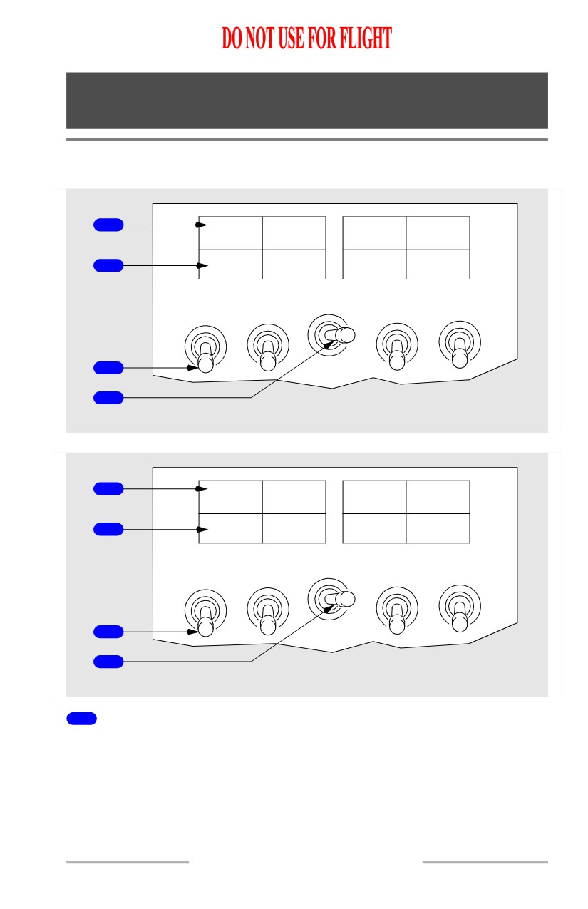
Window Heat Panel
[Option - Green ON Lights]
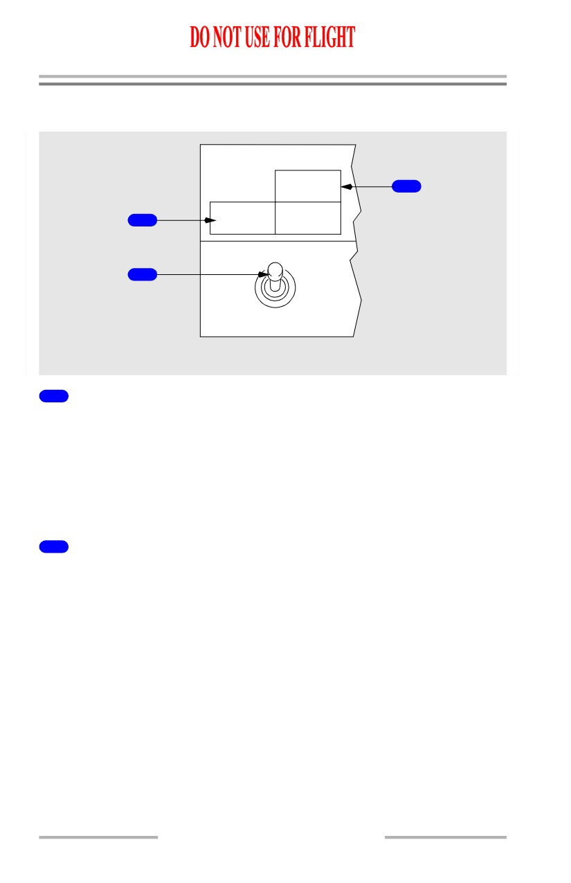
1
OVERHEAT
OVERHEAT
OVERHEAT
OVERHEAT
ON
ON
ON
ON
2
L
WINDOW HEAT
R
OVHT
SIDE
FWD
FWD
SIDE
OFF
OFF
ON
PWR TEST
ON
3
4
FORWARD OVERHEAD PANEL
[Option - Amber OFF Lights]
1
OVERHEAT
OVERHEAT
OVERHEAT
OVERHEAT
OFF
OFF
OFF
OFF
2
L
WINDOW HEAT
R
OVHT
SIDE
FWD
FWD
SIDE
OFF
OFF
ON
PWR TEST
ON
3
4
FORWARD OVERHEAD PANEL
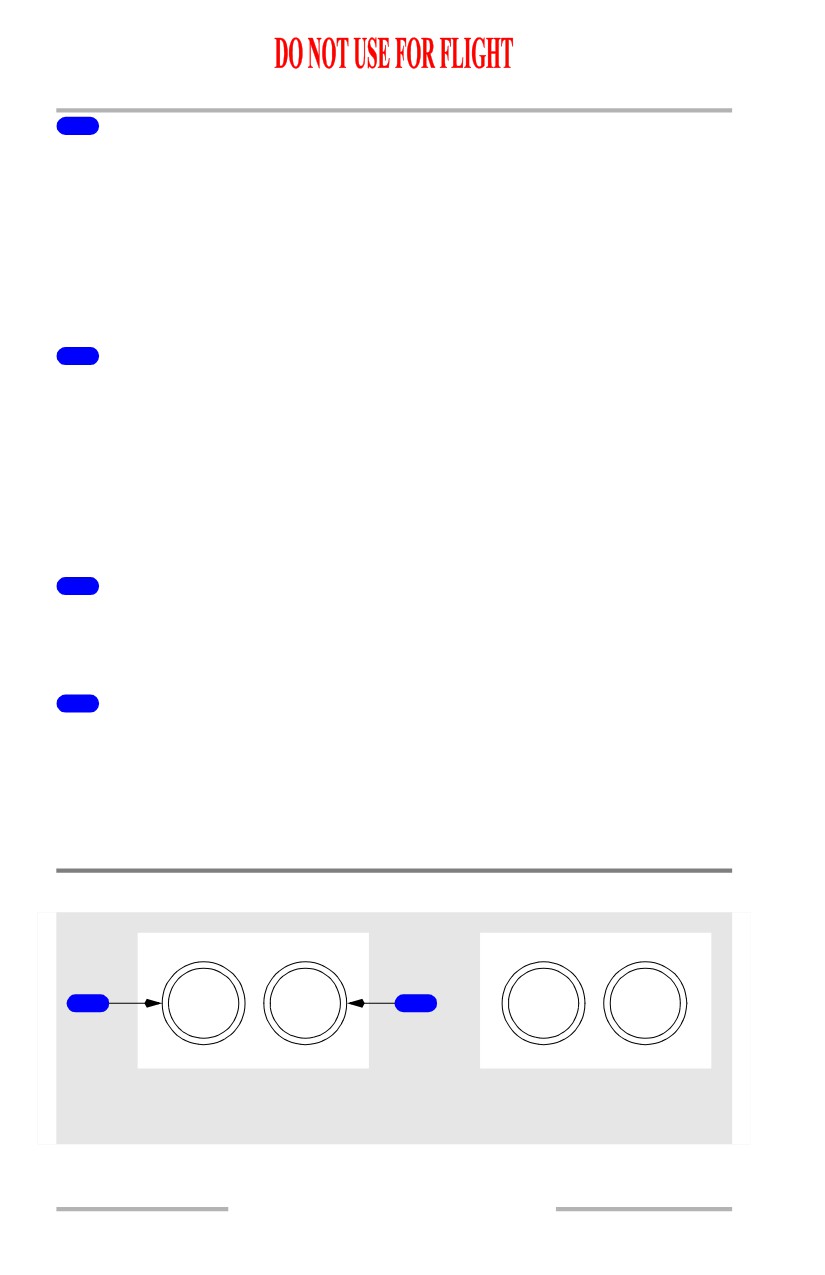
1
Window OVERHEAT Lights
Illuminated (amber) - overheat condition is detected.
Note: OVERHEAT lights also illuminate if electrical power to window(s) is
interrupted.
3.10.1
Anti-Ice, Rain -
Controls and Indicators
Boeing 737 Operations Manual
2
Window Heat ON Lights
[Option - Green ON Lights]
Illuminated (green) - window heat is being applied to selected window(s).
Extinguished -
• switch is OFF, or
• an overheat is detected, or
• a system failure has occurred.
2
Window Heat OFF Lights
[Option - Amber OFF Lights]
Illuminated (amber) -
• switch is OFF, or
• an overheat is detected, or
• a system failure has occurred.
Extinguished - window heat is being applied to selected window(s).
3
WINDOW HEAT Switches
ON - window heat is applied to selected window(s).
OFF - window heat not in use.
4
WINDOW HEAT Test Switch (spring-loaded to neutral)
OVHT - simulates an overheat condition.
PWR TEST - provides a confidence test.
Note: Refer to Supplementary Normal Procedures for Window Heat Test
procedures.
Windshield/Foot Air Controls
FOOT
WIND
WIND
FOOT
1
AIR
SHIELD
2
SHIELD
AIR
AIR
AIR
BELOW CAPTAIN’S
BELOW F/O’S
INST PANEL
INST PANEL
3.10.2
Anti-Ice, Rain -
Controls and Indicators
Boeing 737 Operations Manual
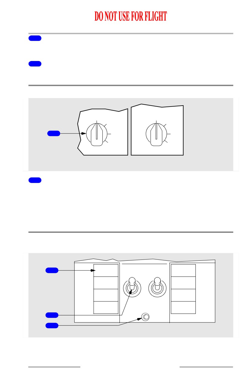
1
FOOT AIR Controls
PULL - supplies conditioned air to pilots’ leg positions.
2
WINDSHIELD AIR Controls
PULL - supplies conditioned air to number 1 windows for defogging.
Windshield Wiper Selector Panel
L WIPER
R WIPER
PARK
PARK
INT
INT
1
LOW
LOW
HIGH
HIGH
FORWARD OVERHEAD PANEL
1
Windshield WIPER Selectors
PARK - turns off wiper motors and stows wiper blades.
INT - seven second intermittent operation.
LOW - low speed operation.
HIGH - high speed operation.
Probe Heat Panel
[Option - Aspirated TAT]
CAPT
PROBE
F/O
1
PITOT
A
B
PITOT
OFF
L ELEV
R ELEV
PITOT
PITOT
L ALPHA
ON
R ALPHA
VANE
VANE
HEAT
TEMP
AUX
PROBE
TAT TEST
PITOT
2
3
FORWARD OVERHEAD PANEL
3.10.3
Anti-Ice, Rain -
Controls and Indicators
Boeing 737 Operations Manual
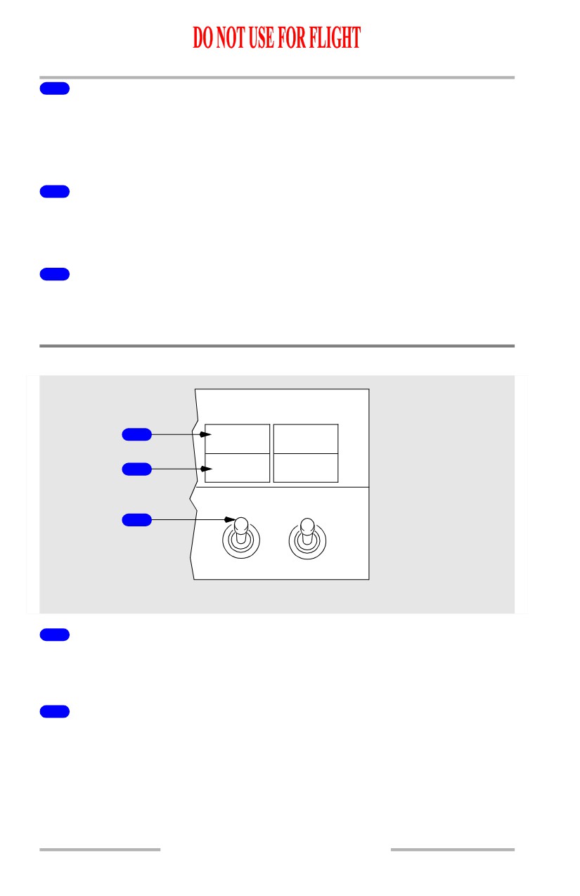
1
Probe Heat Lights
Illuminated (amber) - related probe not heated.
Note: If operating on standby power, probe heat lights do not indicate system
status.
2
PROBE HEAT Switches
ON - power is supplied to heat related system.
OFF - power off.
3
TAT TEST Switch
[Option - Aspirated TAT]
Push - Electrical power applied to TEMP PROBE on the ground.
Engine Anti-Ice Panel
1
COWL
COWL
ANTI-ICE
ANTI-ICE
COWL VALVE
COWL VALVE
2
OPEN
OPEN
ENG
ANTI-ICE
3
OFF
ON
1
2
FORWARD OVERHEAD PANEL
1
COWL ANTI-ICE Lights
Illuminated (amber) - indicates an overpressure condition in duct downstream of
engine cowl anti-ice valve.
2
COWL VALVE OPEN Lights
Illuminated (blue) -
• bright - related cowl anti-ice valve is in transit, or, cowl anti-ice valve
position disagrees with related ENGINE ANTI-ICE switch position
• dim - related cowl anti-ice valve is open (switch ON).
Extinguished - related cowl anti-ice valve is closed (switch OFF).
3.10.4
Anti-Ice, Rain -
Controls and Indicators
Boeing 737 Operations Manual
3
ENGINE ANTI-ICE Switches
ON -
• related engine anti-ice valve is open
• stick shaker logic is set for icing conditions.
OFF -
• related engine anti-ice valve is closed
• stick shaker logic returns to normal if wing anti-ice has not been used in
flight.
Thermal Anti-Ice Indication
1
TAI
TAI
10
87.7
10
87.7
0
0
8
8
2
2
6
6
4
4
N1
UPPER DISPLAY UNIT
1
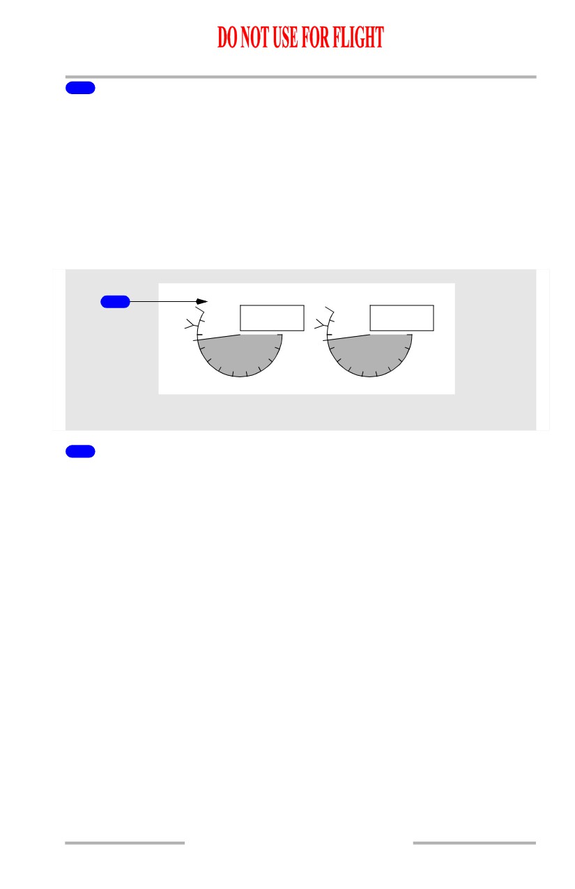
Thermal Anti-Ice Indications
Illuminated -
• Green - cowl anti-ice valve(s) open
• Amber - cowl anti-ice valve is not in position indicated by related engine
anti-ice switch.
3.10.5
Anti-Ice, Rain -
Controls and Indicators
Boeing 737 Operations Manual
Wing Anti-Ice Panel
[Option - ICE DETECTOR System]
ICE
3
DETECTOR
L VALVE
R VALVE
1
OPEN
OPEN
WING ANTI-ICE
OFF
2
ON
FORWARD OVERHEAD PANEL
1
Wing Anti-Ice VALVE OPEN Lights
Illuminated (blue) -
• bright - related wing anti-ice control valve is in transit, or, related wing
anti-ice control valve position disagrees with WING ANTI-ICE switch
position
• dim - related wing anti-ice control valve is open (switch ON).
Extinguished - related wing anti-ice control valve is closed (switch OFF).
2
WING ANTI-ICE Switch
OFF - wing anti-ice control valves are closed.
ON (in the air) -
• wing anti-ice control valves are open
• stick shaker logic is set for icing conditions.
Note: Stick shaker logic remains set for icing conditions for the remainder of
the flight, regardless of subsequent WING ANTI-ICE switch position.
ON (on the ground) -
• wing anti-ice control valves open if thrust on both engines is below
takeoff warning setting and temperature inside both distribution ducts is
below thermal switch activation temperature
• control valves close if either engine thrust is above takeoff warning
setting or thermal switch is activated in either distribution duct. Switch
remains ON
• switch trips OFF at lift-off.
3.10.6
Anti-Ice, Rain -
Controls and Indicators
Boeing 737 Operations Manual
3
ICE DETECTOR Light
[Option - ICE DETECTOR System]
Illuminated (amber) - Ice detector system has failed.
Icing Advisory Lights
[Option - Icing Detector System]
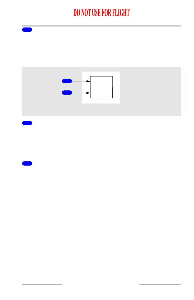
ICING
1
P-CANCEL
NO ICE
2
P-CANCEL
LEFT FORWARD PANEL
1
ICING Light
Illuminated (amber) -
• ice detector is detecting ice
• light is inhibited on the ground.
Press - extinguishes light, if illuminated.
2
NO ICE Light
Illuminated (white) -
• ice detector is not detecting ice, and the ice detector probe had previously
detected ice
• light is inhibited on the ground.
Press - extinguishes light, if illuminated.
3.10.7
Anti-Ice, Rain -
Controls and Indicators
Boeing 737 Operations Manual
Intentionally
Blank
3.10.8
Boeing 737 Operations Manual
Anti-Ice, Rain
Chapter 3
System Description
Section 20
Introduction
Thermal anti-icing (TAI), electrical anti-icing, and windshield wipers are the
systems provided for ice and rain protection.
The anti-ice and rain systems include:
• Flight Deck Window Heat
• Engine Anti-Ice System
• Windshield Wipers
• Wing Anti-Ice System
• Probe and Sensor Heat
[Option]
• Ice Detection System
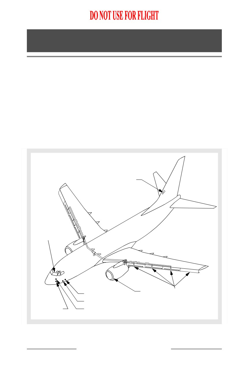
Anti-Ice Components Diagram
[Option - Ice detector probe]
ELEVATOR PITOT
PROBES (2 PLACES)
FLIGHT DECK
WINDOWS
WINDOW HEAT
WINDSHIELD
WIPERS
ENGINE
LEADING EDGE
TEMPERATURE PROBE
COWL LIP
SLATS
ICE DETECTOR PROBE
ALPHA VANES
PITOT PROBES
(2 PLACES)
(3 PLACES)
3.20.1
Anti-Ice, Rain -
System Description
Boeing 737 Operations Manual
Flight Deck Window Heat
[Option - Window # 3 heated]
Flight deck windows consist of glass panes laminated to each side of a vinyl core.
Flight deck window number 4 has an additional vinyl layer and acrylic sheet
laminated to the inside surface.
[Option - Window # 3 heated]
A conductive coating on the outer glass pane of window numbers 1 and 2 permits
electrical heating to prevent ice build-up and fogging. A conductive coating on
the inner glass pane of window numbers 3, 4 and 5 permits electrical heating to
prevent fogging.
[Option - Window # 3 not heated]
Flight deck window numbers 1, 2, 4 and 5 consist of glass panes laminated to each
side of a vinyl core. Flight deck window number 4 has an additional vinyl layer
and acrylic sheet laminated to the inside surface. Flight deck window number 3
consists of two acrylic panes separated by an air space.
[Option - Window # 3 not heated]
A conductive coating on the outer glass pane of window numbers 1 and 2 permits
electrical heating to prevent ice build-up and fogging. A conductive coating on
the inner glass pane of window numbers 4 and 5 permits electrical heating to
prevent fogging. Window number 3 is not electrically heated.
Flight Deck Window Heat Operation
[Option -Window # 3 heated]
The FWD WINDOW HEAT switches control heat to window number 1. The
SIDE WINDOW HEAT switches control heat to window numbers 2, 3, 4 and 5.
[Option -Window # 3 heated]
Temperature controllers maintain windows numbers 1 and 2 at the correct
temperature to ensure maximum strength of the windows in the event of bird
impact. Power to window numbers 1 and 2 is automatically removed if an
overheat condition is detected. Thermal switches, located on window numbers 3
and 5, open and close to maintain the correct temperature of window numbers 3,
4, and 5.
[Option - Window # 3 not heated]
The FWD WINDOW HEAT switches control heat to window No. 1. The SIDE
WINDOW HEAT switches control heat to window numbers 2, 4 and 5.
3.20.2
Anti-Ice, Rain -
System Description
Boeing 737 Operations Manual
[Option - Window # 3 not heated]
Temperature controllers maintain window numbers
1 and 2 at the correct
temperature to ensure maximum strength of the windows in the event of bird
impact. Power to window numbers 1 and 2 is automatically removed if an
overheat condition is detected. A thermal switch located on window 5 opens and
closes to maintain the correct temperature of window numbers 4, and 5.
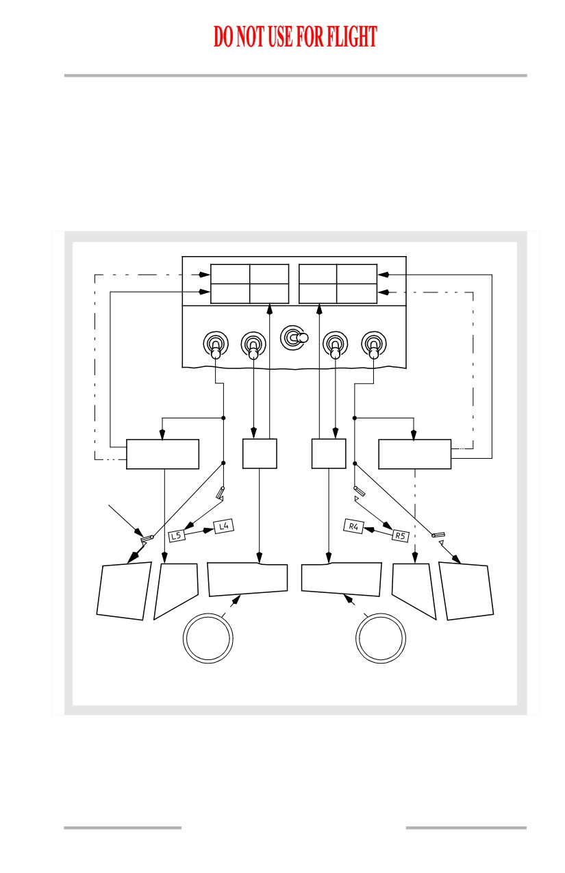
Flight Deck Window Heat Schematic
[Option -Window # 3 heated and green ON lights]
OVERHEAT
ON
ON
ON
L
WINDOW HEAT
R
OVHT
SIDE
FWD
FWD
SIDE
OFF
OFF
ON
PWR TEST
ON
TEMPERATURE
TEMP
TEMP
TEMPERATURE
CONTROLLER
CONT
CONT
CONTROLLER
THERMAL
SWITCH
L1
R1
L3
L2
R2
R3
WIND
FROM
WIND
AIR CONDITIONING
SHIELD
SHIELD
SYSTEM
AIR
AIR
CONDITION:
WINDOW HEAT ON
R SIDE OVERHEATED
3.20.3