Boeing 737 - 600/700/800/900. Operations Manual (1997 year) - page 27
Air Systems -
Bleed Air System Description
Boeing 737 Operations Manual
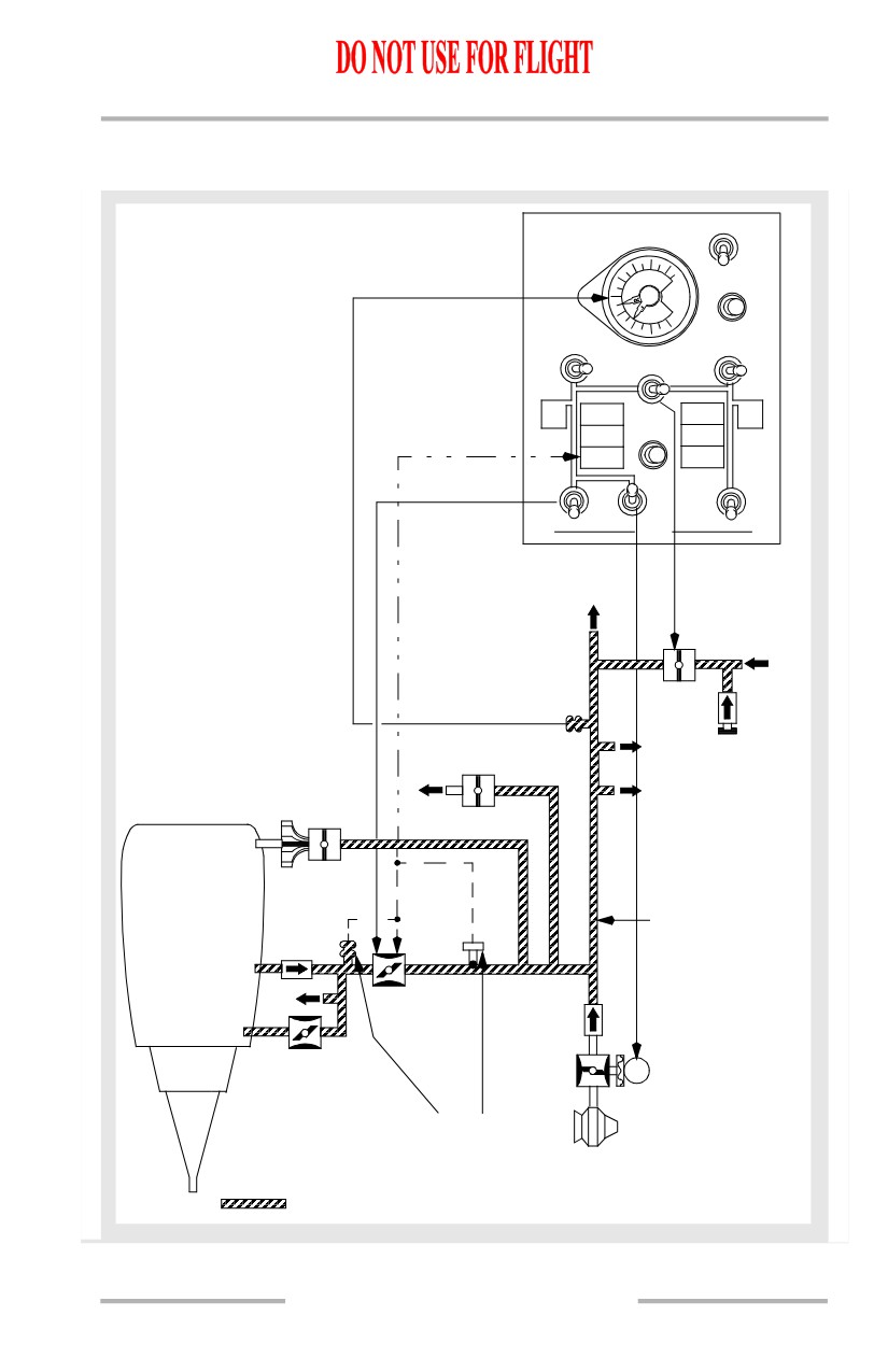
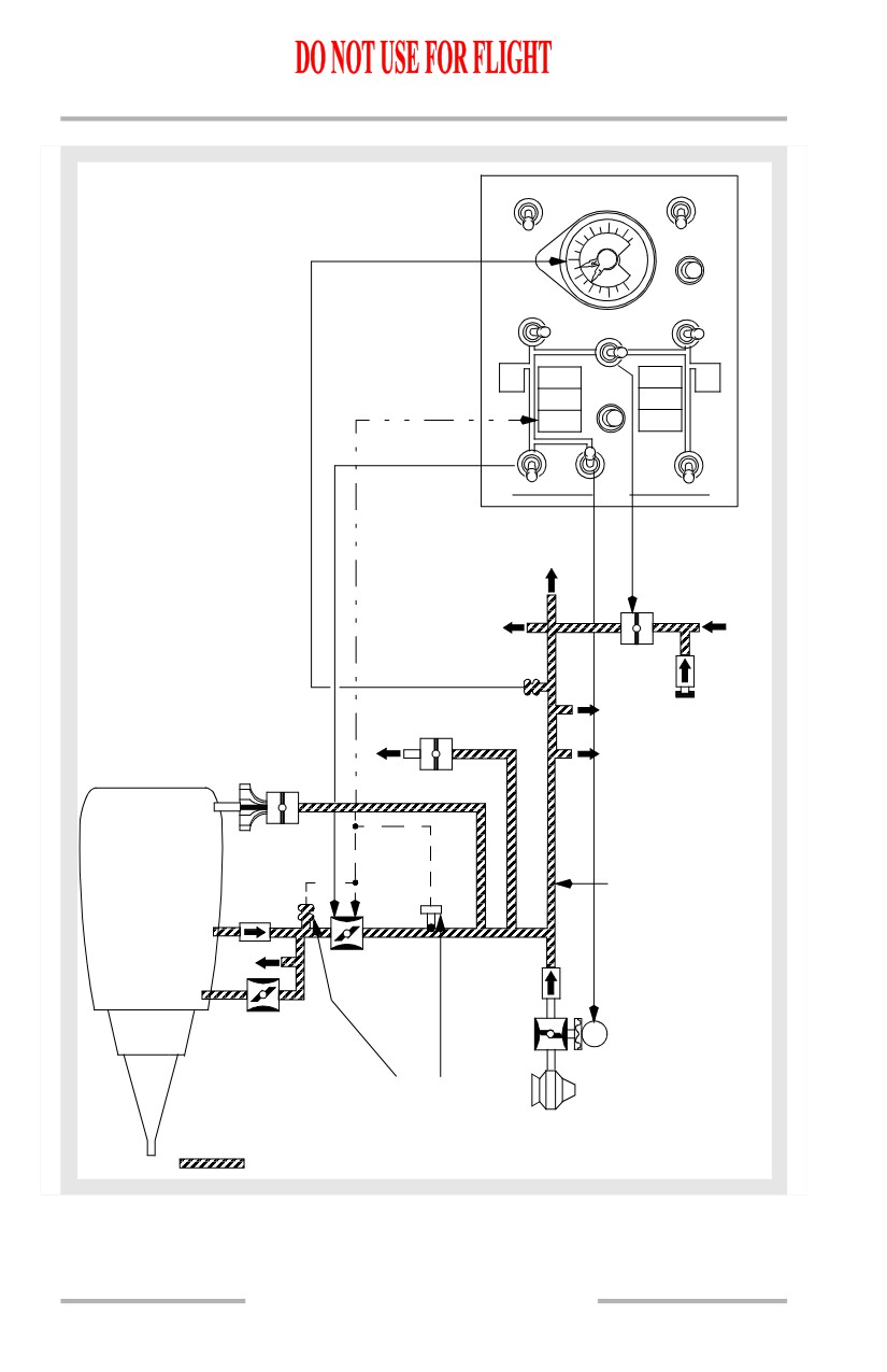
Duct Pressure Transmitters
Duct pressure transmitters provide bleed air pressure indications to the respective
(L and R) pointers on the bleed air duct pressure indicator. The indicator is AC
operated. Differences between L and R duct pressure on the bleed air duct pressure
indicator are considered normal as long as there is sufficient air for cabin
pressurization.
Isolation Valve
The isolation valve isolates the left and right sides of the bleed air duct during
normal operations. The isolation valve is AC operated.
With the isolation valve switch in AUTO, both engine bleed air switches ON, and
both air conditioning pack switches AUTO or HIGH, the isolation valve is closed.
The isolation valve opens if either engine bleed air switch or air conditioning pack
switch is positioned OFF. Isolation valve position is not affected by the APU bleed
air switch.
External Air Connection
An external air cart/source provides an alternate air source for engine start or air
conditioning.
APU Bleed Air Valve
The APU bleed air valve permits APU bleed air to flow to the bleed air duct. The
valve closes automatically when the APU is shut down. The APU bleed air valve
is DC controlled and pressure operated.
With both the APU and engine bleed air valves open, and the engines operating at
idle thrust, there is a possibility of APU bleed air backpressuring the 9th stage
modulating and shutoff valve. This would cause the 9th stage valve to close.
DUAL BLEED Light
The DUAL BLEED light illuminates whenever the APU bleed air valve is open
and the position of the engine bleed air switches and isolation valve would permit
possible backpressure of the APU. Therefore, thrust must be limited to idle with
the DUAL BLEED light illuminated.
2.20.2
Air Systems -
Bleed Air System Description
Boeing 737 Operations Manual
Bleed Air System Schematic
[737 - 600/700 without Aspirated TAT]
RECIRC FAN
OFF
AUTO
60
80
DUCT
OVHT
40
PRESS
PSI
20
0
TEST
L PACK
ISOLATION
R PACK
OFF
VALVE
OFF
AUTO
CLOSE
AUTO
HIGH
AUTO
HIGH
WING
PACK
OPEN
PACK
WING
ANTI
TRIP OFF
TRIP OFF
ANTI
ICE
ICE
WING-BODY
WING-BODY
OVERHEAT
TRIP
OVERHEAT
BLEED
BLEED
TRIP OFF
TRIP OFF
RESET
OFF
OFF
ON
ON
1
APU
2
BLEED
TO
PACK
VALVE
FROM
RIGHT
ENGINE
ISOLATION
VALVE
DUCT PRESSURE
TRANSMITTER
TO HYD
EXTERNAL
WING
RESV
AIR
TAI
CONNECTION
TO
STARTER
WATER
VALVE
TANK
STARTER
BLEED
AIR DUCT
5th
STAGE
COWL
ENGINE
TAI
9th
BLEED AIR
STAGE
VALVE
HIGH STAGE
S APU BLEED
VALVE
AIR VALVE
BLEED
AP
U
TRIP
CONDITION:
SENSORS
ENGINES OPERATING
& SUPPLYING AIR
BLEED AIR
CONDITIONING PACKS
2.20.3
Air Systems -
Bleed Air System Description
Boeing 737 Operations Manual
[737 - 800/900 with Aspirated TAT]
L RECIRC FAN
R RECIRC FAN
OFF
OFF
AUTO
AUTO
60
80
DUCT
OVHT
40
PRESSPSI
20
0
TEST
L PACK
R PACK
ISOLATION
OFF
VALVE
OFF
AUTO
CLOSE
AUTO
HIGH
AUTO
HIGH
WING
WING
ANTI
PACK
OPEN
PACK
ANTI
ICE
ICE
WING-BODY
WING-BODY
OVERHEAT
TRIP
OVERHEAT
BLEED
BLEED
TRIP OFF
TRIP OFF
RESET
OFF
OFF
ON
ON
1
APU
2
BLEED
TO
PACK
VALVE
FROM
RIGHT
ENGINE
TO ASPIRATED
TAT PROBE
ISOLATION
VALVE
DUCT PRESSURE
TRANSMITTER
TO HYD
EXTERNAL
WING
RESV
AIR
TAI
CONNECTION
TO
STARTER
WATER
VALVE
TANK
STARTER
BLEED
AIR DUCT
5th
STAGE
COWL
ENGINE
TAI
9th
BLEED AIR
STAGE
VALVE
HIGH STAGE
S
APU BLEED
VALVE
AIR VALVE
BLEED
AP
U
TRIP
CONDITION:
SENSORS
ENGINES OPERATING
& SUPPLYING AIR
BLEED AIR
CONDITIONING PACKS
2.20.4
Air Systems -
Bleed Air System Description
Boeing 737 Operations Manual
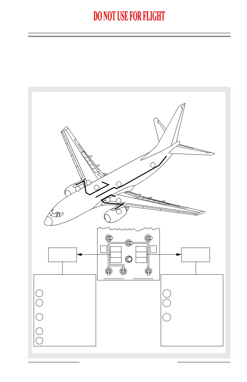
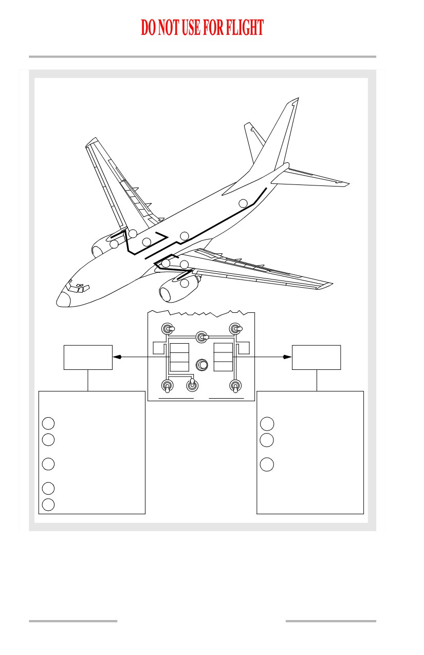
Wing-Body Overheat
A wing-body overheat condition is caused by a bleed air duct leak. It is sensed by
the overheat sensors located as shown.
Wing-Body Overheat Ducts and Lights
[737 - 600/700]
5
7
4
6
8
3
2
1
L PACK
ISOLATION
R PACK
OFF
VALVE
OFF
AUTO
CLOSE
AUTO
HIGH
AUTO
HIGH
WING
PACK
OPEN
PACK
WING
ANTI
TRIP OFF
TRIP OFF
ANTI
WING-BODY
ICE
ICE
WING-BODY
WING-BODY
TRIP
WING-BODY
OVERHEAT
OVERHEAT
OVER HEAT
BLEED
BLEED
OVER HEAT
TRIP OFF
TRIP OFF
RESET
OFF
OFF
ON
ON
1
APU
2
LEFT LIGHT
BLEED
RIGHT LIGHT
Sensors located:
FORWARD OVERHEAD PANEL
Sensors located:
1
Left engine strut.
6
Right engine strut.
2
Left inboard wing
7
Right inboard wing
leading edge.
leading edge.
3
Left-hand air
8
Right-hand air
conditioning bay.
conditioning bay.
4
Keel beam.
5
Bleed duct from APU.
2.20.5
Air Systems -
Bleed Air System Description
Boeing 737 Operations Manual
[737 - 800/900]
5
7
4
6
8
3
2
1
L PACK
ISOLATION
R PACK
OFF
VALVE
OFF
AUTO
CLOSE
AUTO
HIGH
AUTO
HIGH
WING
OPEN
WING
ANTI
PACK
PACK
ANTI
WING-BODY
ICE
ICE
WING-BODY
WING-BODY
TRIP
WING-BODY
OVERHEAT
OVERHEAT
OVER HEAT
BLEED
BLEED
OVER HEAT
TRIP OFF
TRIP OFF
RESET
OFF
OFF
ON
ON
1
APU
2
LEFT LIGHT
BLEED
RIGHT LIGHT
Sensors located:
FORWARD OVERHEAD PANEL
Sensors located:
1
Left engine strut.
6
Right engine strut.
2
Left inboard wing
7
Right inboard wing
leading edge.
leading edge.
3
Left-hand air
8
Right-hand air
conditioning bay.
conditioning bay.
4
Keel beam.
5
Bleed duct from APU.
2.20.6
Boeing 737 Operations Manual
Air Systems
Chapter 2
Air Conditioning System Description
Section 30
[737-600/700]
2.30 Air Systems-Air Conditioning System Description
Introduction
Conditioned air for the cabin comes from either the airplane air conditioning
system or a preconditioned ground source. Air from the preconditioned ground
source enters the air conditioning system through the mix manifold.
The air conditioning system provides temperature controlled air by processing
bleed air from the engines, APU, or a ground air source in air conditioning packs.
Conditioned air from the left pack, upstream of the mix manifold, flows directly
to the flight deck. Excess air from the left pack, air from the right pack, and air
from the recirculation system is combined in the mix manifold. The mixed air is
then distributed through the left and right sidewall risers to the passenger cabin.
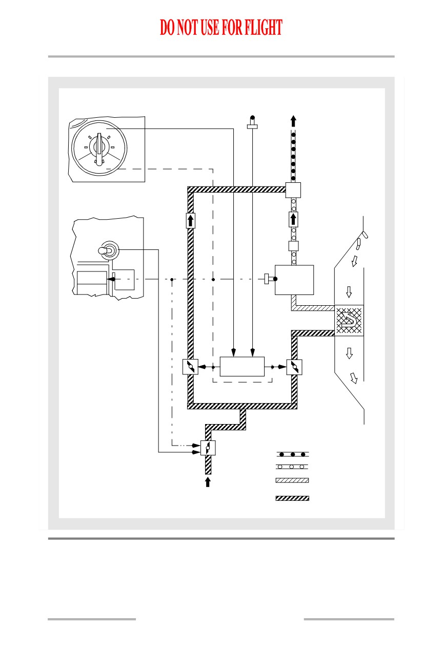
Air Conditioning Pack
The flow of bleed air from the main bleed air duct through each air conditioning
pack is controlled by the respective pack valve. Normally the left pack uses bleed
air from engine No. 1 and the right pack uses bleed air from engine No. 2. A single
pack is capable of maintaining pressurization and acceptable temperatures
throughout the airplane up to the maximum certified ceiling.
The APU is capable of supplying bleed air for two packs on the ground, or one
pack in flight. Most external air carts are capable of supplying adequate bleed air
for two pack operation. Do not operate more than one pack from one engine at any
time.
Airflow Control
With both air conditioning pack switches in AUTO and both packs operating, the
packs provide “normal air flow”. However, with one pack not operating, the other
pack automatically switches to “high air flow” in order to maintain the necessary
ventilation rate. This automatic switching is inhibited when the airplane is on the
ground, or inflight with the flaps extended, to insure adequate engine power for
single engine operation. Automatic switching to “high air flow” occurs if both
engine bleed air switches are OFF and the APU bleed air switch is ON, regardless
of flap position, air/ground status or number of packs operating.
With the air conditioning pack switch in HIGH, the pack provides “high air flow”.
Additionally, an “APU high air flow” rate is available when the airplane is on the
ground, the APU bleed air switch is ON and either or both pack switches are
positioned to HIGH. This mode is designed to provide the maximum airflow when
the APU is the only source of bleed air.
2.30.1
Air Systems -
Air Conditioning System
Description
Boeing 737 Operations Manual
Ram Air System
The ram air system provides cooling air for the heat exchangers. Operation of the
system is automatically controlled by the packs through operation of ram air inlet
doors.
On the ground, or during slow flight with the flaps not fully retracted, the ram air
inlet doors move to the full open position for maximum cooling. In normal cruise,
the doors modulate between open and closed. A RAM DOOR FULL OPEN light
illuminates whenever a ram door is fully open.
Deflector doors are installed forward of the ram air inlet doors to prevent slush
ingestion prior to liftoff and after touchdown. Deflector doors extend when
activated electrically by the air-ground safety sensor.
Cooling Cycle
The flow through the cooling cycle starts with bleed air passing through a heat
exchanger for cooling. The air then flows to an air cycle machine for refrigeration
and to a water separator which removes moisture. The processed cold air is then
combined with hot air. The conditioned air flows into the mix manifold and
distribution system.
Overheat protection is provided by temperature sensors located in the cooling
cycle. An overheat condition causes the pack valve to close and the PACK TRIP
OFF light to illuminate.
Air Mix Valves
The two air mix valves for each pack control hot and cold air according to the
setting of the CONT CABIN or PASS CABIN temperature selector. Air that flows
through the cold air mix valve is processed through a cooling cycle and then
combined with hot air flowing from the hot air mix valve.
In the automatic temperature mode, the air mix valves are operated by the
automatic temperature controller. The automatic temperature controller uses
inputs from the respective temperature selector and cabin temperature sensor. The
automatic temperature controller is bypassed when the temperature selector is
positioned to MANUAL.
Anytime the pack valve closes, the air mix valves are driven to the full cold
position automatically. This aids startup of the cooling cycle and prevents
nuisance hot air trips when the pack is turned on.
2.30.2
Air Systems -
Air Conditioning System
Description
Boeing 737 Operations Manual
Air Conditioning Pack Schematic
PASS
TO MIX
CABIN
MANIFOLD
AUTO
COOL
WARM
COOL WARM
MANUAL
MIXING
CHAMBER
R PACK
OFF
WATER
AUTO
SEPARATOR
RAM
HIGH
AIR
WING
AIR
PACK
TRIP OFF
ANTI
CYCLE
ICE
MACHINE
WING-BODY
OVERHEAT
AUTO TEMP
CONTROLLER
HOT AIR
COLD AIR
MIX VALVE
MIX VALVE
PACK
VALVE
CONDITIONED AIR
COLD AIR
HEAT EXCHANGER
COOLED AIR
RIGHT
BLEED AIR
BLEED AIR
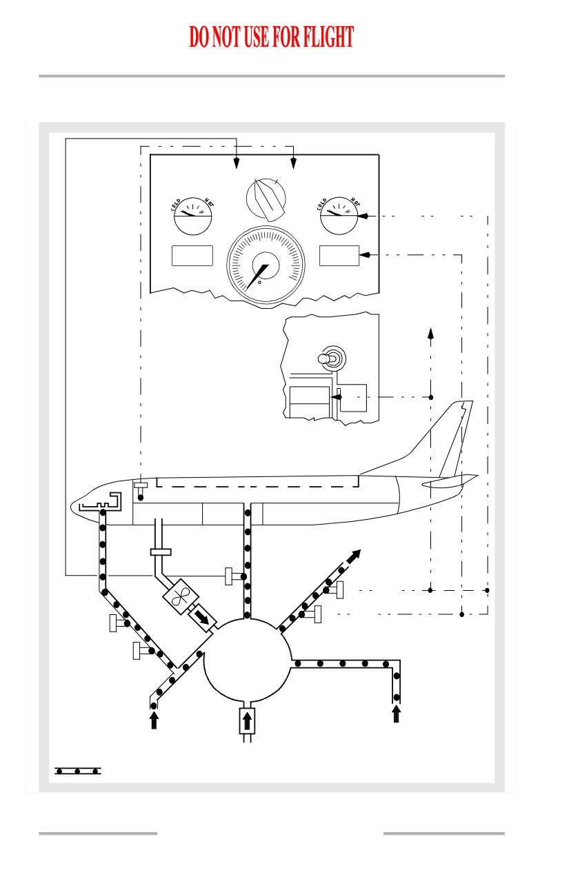
Air Conditioning Distribution
Conditioned air is collected in the mix manifold. The temperature of the air is
directly related to the setting of the CONT CABIN and PASS CABIN temperature
selectors.
2.30.3
Air Systems -
Air Conditioning System
Description
Boeing 737 Operations Manual
Overheat detection is provided by temperature sensors located downstream of the
packs. An overheat condition causes the appropriate mix valves to drive full cold
and the DUCT OVERHEAT light to illuminate. A temperature higher than the
duct overheat causes the appropriate pack valve to close and the PACK TRIP OFF
light to illuminate.
Flight Deck
Since the flight deck requires only a fraction of the air supply provided by the left
pack, most of the left pack air output is mixed with the right pack supply and
routed to the passenger cabin.
Conditioned air for the flight deck branches into several risers which end at the
floor, ceiling, and foot level outlets. Air diffusers on the floor under each seat
deliver continuous air flow as long as the manifold is pressurized.
Overhead diffusers are located on the flight deck ceiling, above and aft of the No.
3 windows. Each of these outlets can be opened or closed as desired by turning a
slotted adjusting screw.
There is also a dual purpose valve behind the rudder pedals of each pilot. These
valves provide air for warming the pilots’ feet and for defogging the inside of the
No. 1 windshields. Each valve is controlled by knobs located on the Captain’s and
First Officer’s panel, respectively.
Passenger Cabin
The passenger cabin air supply distribution system consists of the mix manifold,
sidewall risers, and an overhead distribution duct.
Sidewall risers go up the right and left wall of the passenger cabin to supply air to
the overhead distribution duct. The overhead distribution duct routes conditioned
air to the passenger cabin. It extends from the forward to the aft end of the ceiling
along the airplane centerline and also supplies the sidewall diffusers.
Recirculation Fan
The recirculation fan system reduces the air conditioning system pack load and the
engine bleed air demand. Air from the passenger cabin and electrical equipment
bay is drawn to the forward cargo bay where it is filtered and recirculated to the
mix manifold. The fan is driven by an AC motor. The fan operates with the recirc
fan switch in AUTO except with both packs on and one or both in HIGH.
Equipment Cooling
The equipment cooling system cools electronic equipment in the flight deck and
the E & E bay.
2.30.4
Air Systems -
Air Conditioning System
Description
Boeing 737 Operations Manual
The equipment cooling system consists of a supply duct and an exhaust duct. Each
duct has a normal fan and an alternate fan. The supply duct supplies cool air to the
flight deck displays and electronic equipment in the E & E bay. The exhaust duct
collects and discards warm air from the flight deck displays, the overhead and aft
electronic panels, circuit breaker panels in the flight deck, and electronic
equipment in the E & E bay.
Loss of airflow due to failure of an equipment cooling fan results in illumination
of the related equipment cooling OFF light. Selecting the alternate fan should
restore airflow and extinguish the OFF light within approximately 5 seconds.
If an overtemperature occurs on the ground, alerting is provided through the crew
call horn in the nose wheel well.
Forward Cargo Compartment
The recirculation fan system circulates air from the passenger cabin around the
lining of the forward cargo compartment. When the overboard exhaust valve is
closed, exhaust air from the equipment cooling system is also diffused to the lining
of the forward cargo compartment for additional inflight heating.
Conditioned Air Source Connection
A ground air conditioning source may be connected to the mix manifold to
distribute preconditioned air throughout the airplane.
2.30.5
Air Systems -
Air Conditioning System
Description
Boeing 737 Operations Manual
Air Conditioning Distribution Schematic
[Option - Air Temperature Indicator in degrees C]
CONT CABIN
AIR TEMP PASS CABIN
SUPPLY
PASS
DUCT
CABIN
AIR MIX
AIR MIX
VALVE
VALVE
DRIVES MIX VALVES
FULL COLD
40
60
TEMP
DUCT
80
DUCT
OVERHEAT
OVERHEAT
20
100
0
C
TO
RIGHT
PACK
VALVE
R PACK
OFF
AUTO
HIGH
PACK
WING
TRIP OFF
ANTI
ICE
WING-BODY
OVERHEAT
TO RIGHT SIDEWALL
RISER
FILTER
LEFT SIDEWALL
RISER
RIGHT PACK
RECIRC
TRIP OFF
FAN
RIGHT DUCT
LEFT PACK
OVERHEAT
TRIP OFF
LEFT DUCT
OVERHEAT
MIX
MANIFOLD
FROM RIGHT PACK
FROM LEFT PACK
GROUND
PRECONDITIONED
CONDITION: IN FLIGHT
CONDITIONED AIR
AIR SOURCE
PACKS ON
2.30.6
Boeing 737 Operations Manual
Air Systems
Chapter 2
Air Conditioning System Description
Section 31
[737-800/900]
2.31 Air Systems-Air Conditioning System Description
Introduction
Conditioned air for the cabin comes from either the airplane air conditioning
system or a preconditioned ground source. Air from the preconditioned ground
source enters the air conditioning system through the mix manifold.
The air conditioning system provides temperature controlled air by processing
bleed air from the engines, APU, or a ground air source in air conditioning packs.
Conditioned air from the left pack, upstream of the mix manifold, flows directly
to the flight deck. Excess air from the left pack, air from the right pack, and air
from the recirculation system is combined in the mix manifold. The mixed air is
then distributed through the left and right sidewall risers to the passenger cabin.
Air Conditioning Pack
The flow of bleed air from the main bleed air duct through each air conditioning
pack is controlled by the respective pack valve. Normally, the left pack uses bleed
air from engine No. 1 and the right pack uses bleed air from engine No. 2. A single
pack is capable of maintaining pressurization and acceptable temperatures
throughout the airplane up to the maximum certified ceiling.
The APU is capable of supplying bleed air for two packs on the ground, or one
pack in flight. Most external air carts are capable of supplying adequate bleed air
for two pack operation. Do not operate more than one pack from one engine at any
time.
Airflow Control
With both air conditioning pack switches in AUTO and both packs operating, the
packs provide “normal air flow”. However, with one pack not operating, the other
pack automatically switches to “high air flow” in order to maintain the necessary
ventilation rate. This automatic switching is inhibited when the airplane is on the
ground, or inflight with the flaps extended, to insure adequate engine power for
single engine operation. Automatic switching to “high air flow” occurs if both
engine bleed air switches are OFF and the APU bleed air switch is ON, regardless
of flap position, air/ground status or number of packs operating.
With the air conditioning pack switch in HIGH, the pack provides “high air flow”.
Additionally, an “APU high air flow” rate is available when the airplane is on the
ground, the APU bleed air switch is ON and either or both pack switches are
positioned to HIGH. This mode is designed to provide the maximum airflow when
the APU is the only source of bleed air.
2.31.1
Air Systems -
Air Conditioning System
Description
Boeing 737 Operations Manual
Ram Air System
The ram air system provides cooling air for the heat exchangers. Operation of the
system is automatically controlled by the packs through operation of ram air inlet
doors.
On the ground, or during slow flight with the flaps not fully retracted, the ram air
inlet doors move to the full open position for maximum cooling. In normal cruise,
the doors modulate between open and closed. A RAM DOOR FULL OPEN light
illuminates whenever a ram door is fully open.
Deflector doors are installed forward of the ram air inlet doors to prevent slush
ingestion prior to liftoff and after touchdown. Deflector doors extend when
activated electrically by the air-ground safety sensor.
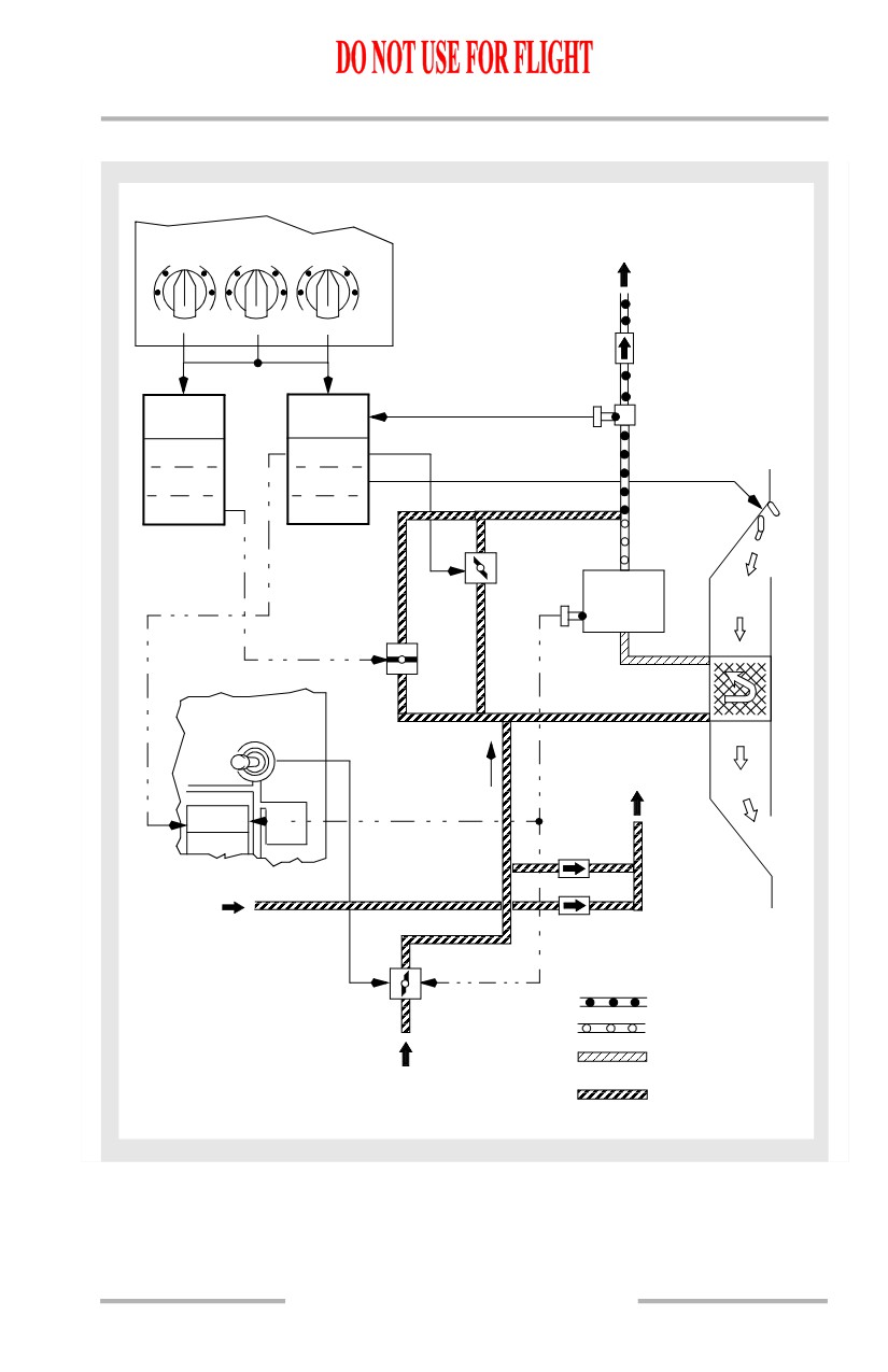
Cooling Cycle
Flow through the cooling cycle starts with bleed air passing through a heat
exchanger for cooling. The air then flows to an air cycle machine for refrigeration.
The processed cold air is then combined with hot air which has bypassed the air
cycle machine, then through a high pressure water separator which removes
moisture. This conditioned air then flows into the mix manifold and distribution
system.
Overheat protection is provided by temperature sensors located in the cooling
cycle. An overheat condition causes the pack valve to close and the PACK light to
illuminate.
Pack Temperature Control
Electronic controllers command the pack temperature control valve toward open
or closed to satisfy pack discharge requirements.
If a primary pack control fails, the affected pack is controlled by the standby pack
control in the opposite controller. A primary or standby pack control failure causes
the PACK, MASTER CAUTION and AIR COND System Annunciator lights to
illuminate during recall.
If both the primary and the standby pack controls fail for the same pack, the
PACK, MASTER CAUTION, and AIR COND System Annunciator lights
illuminate. The pack will continue to operate without control unless excessive
temperatures cause the pack to trip off.
2.31.2
Air Systems -
Air Conditioning System
Description
Boeing 737 Operations Manual
Air Conditioning Pack Schematic
TO MIX
CONT CAB FWD CAB AFT CAB
MANIFOLD
AUTO
AUTO
AUTO
C
W C
W C
W
OFF
OFF
OFF
L
R
ELECTRONIC
ELECTRONIC
WATER
SEPARATOR
CONTROLLER
CONTROLLER
L PRIMARY
R PRIMARY
PACK CONTROL
PACK CONTROL
L RAM
R RAM
AIR CONTROL
AIR CONTROL
R STBY
L STBY
PACK CONTROL
PACK CONTROL
PACK
RAM
TEMP
AIR
CONT
AIR
VALVE
CYCLE
MACHINE
STBY
PACK
TEMP
CONT
VALVE
R PACK
OFF
AUTO
TO
TRIM
HIGH
AIR
SYSTEM
WING
PACK
ANTI
ICE
WING-BODY
OVERHEAT
LEFT
BLEED
AIR
PACK
CONDITIONED AIR
VALVE
COLD AIR
HEAT EXCHANGER
RIGHT
COOLED AIR
BLEED AIR
BLEED AIR
2.31.3
Air Systems -
Air Conditioning System
Description
Boeing 737 Operations Manual
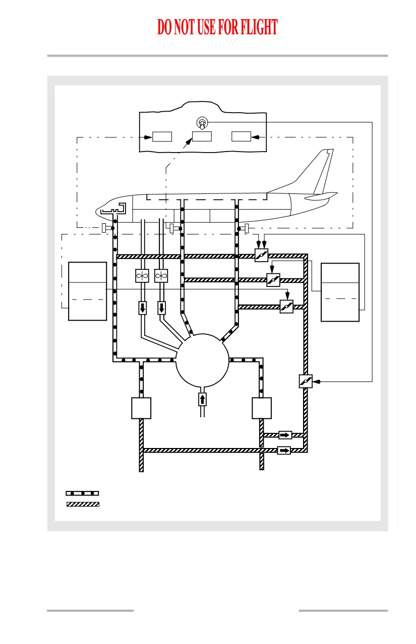
Zone Temperature Control
There are three zones: flight deck, forward cabin and aft cabin. Desired zone
temperature is set by adjusting the individual Temperature Selectors. The selector
range is approximately 65°F (18°C) to 85°F (30°C).
The packs produce an air temperature that satisfies the zone which requires the
most cooling. Zone temperature is controlled by introducing the proper amount of
trim air to the zone supply ducts. The quantity of trim air is regulated by individual
trim air modulating valves.
During single pack operation with the TRIM AIR selected ON, zone temperature
is controlled the same as during two pack operation. During single pack operation
with the TRIM AIR selected OFF, the pack attempts to produce an air temperature
to satisfy the average temperature demands of all three zones.
If air in a zone supply duct overheats, the associated amber ZONE TEMP light
illuminates, and the associated trim air modulating valve closes. The trim air
modulating valve may be reopened after the duct has cooled by pushing the TRIP
RESET Switch.
Zone Temperature Control Modes
The left electronic controller controls the aft cabin zone and provides backup
control for the flight deck. The right controller controls the forward cabin zone and
provides primary control for the flight deck.
Failure of the primary flight deck temperature control will cause an automatic
switch to the back up control and will illuminate the CONT CAB amber ZONE
TEMP light upon Master Caution Recall. Failure of both the primary and standby
controls will illuminate the lights automatically.
Failure of the forward or aft cabin temperature control will cause the associated
trim air modulating valve to close. The Temperature Selectors operate normally,
but the Temperature Selector settings of the two passenger cabin zones will be
averaged. The amber ZONE TEMP light will illuminate upon Master Caution
Recall to indicate failure of the associated zone control.
Unbalanced Pack Temperature Control Mode
Any failure affecting the supply of trim air will cause the temperature control
system to control both packs independently. If flight deck trim air is lost, the left
pack will provide conditioned air to the flight deck at the selected temperature and
the right pack will satisfy the demand of the passenger zone which requires the
most cooling. If a passenger cabin zone trim air, or all trim air is lost, the forward
and aft zone temperature demands will be averaged for control of the right pack.
If any individual zone is switched OFF, the Temperature Selector setting will be
ignored by the temperature control system.
2.31.4
Air Systems -
Air Conditioning System
Description
Boeing 737 Operations Manual
Standby Pack Average Temperature
If all zone controls and primary pack controls fail, the standby pack controls
command the packs to produce air temperatures which will satisfy the average
temperature demand of the two cabin zones. The trim air modulating valves will
close. The flight deck zone Temperature Selector will have no affect on the
standby pack controls.
Fixed Cabin Temperature
If all Temperature Selectors are positioned OFF, the pack controls will cause the
left pack to maintain a fixed temperature of 75°F (24°C) and the right pack to
maintain 65°F (18°C) as measured at the pack temperature sensor.
Air Conditioning Distribution
Conditioned air is collected in the mix manifold. The temperature of the air is
directly related to the setting of the Temperature Selectors.
Overheat detection is provided by temperature sensors located downstream of the
packs and the mix manifold. An overheat condition causes the appropriate trim air
modulating valve to close and the ZONE TEMP light to illuminate.
Flight Deck
Since the flight deck requires only a fraction of the air supply provided by the left
pack, most of the left pack output is routed to the mix manifold.
Conditioned air for the flight deck branches into several risers which end at the
floor, ceiling and foot level outlets. Air diffusers on the floor under each seat
deliver continuous air flow as long as the manifold is pressurized.
Overhead diffusers are located on the flight deck ceiling, above and aft of the No.
3 windows. Each of these outlets can be opened or closed as desired by turning a
slotted adjusting screw.
There is also a dual purpose valve behind the rudder pedal of each pilot. These
valves provide air for warming the pilots' feet and for defogging the inside of the
No. 1 windshields. Each valve is controlled by knobs located on the Captain's and
First Officer's panels.
Passenger Cabin
The passenger cabin air supply distribution system consists of the mix manifold,
sidewall risers, and an overhead distribution duct.
Sidewall risers go up the right and left walls of the passenger cabin to supply air
to the overhead distribution duct. The overhead distribution duct routes
conditioned air to the passenger cabin. It extends from the forward to the aft end
of the ceiling along the airplane centerline and also supplies the sidewall diffusers.
2.31.5
Air Systems -
Air Conditioning System
Description
Boeing 737 Operations Manual
Recirculation Fan
The recirculation fan system reduces the air conditioning system pack load and the
engine bleed air demand. Air from the passenger cabin and electrical equipment
bay is drawn to the forward cargo bay where it is filtered and recirculated to the
mix manifold. The fans are driven by AC motors. Each recirculation fan operates
only if the respective RECIRC FAN Switch is selected to AUTO. In flight, the left
recirculation fan operates if both packs are operating unless either PACK switch
is in HIGH. The right recirculation fan operates in flight if both packs are
operating unless both PACK switches are in HIGH. On the ground, the left
recirculation fan operates unless both PACK switches are in HIGH and the right
recirculation fan operates even if both PACK switches are in HIGH.
Equipment Cooling
The equipment cooling system cools electronic equipment in the flight deck and
the E & E bay.
The equipment cooling system consists of a supply duct and an exhaust duct. Each
duct has a normal fan and an alternate fan. The supply duct supplies cool air to the
flight deck displays and electronic equipment in the E & E bay. The exhaust duct
collects and discards warm air from the flight deck displays, the overhead and aft
electronic panels, circuit breaker panels in the flight deck, and electronic
equipment in the E & E bay.
Loss of airflow due to failure of an equipment cooling fan results in illumination
of the related equipment cooling OFF light. Selecting the alternate fan should
restore airflow and extinguish the OFF light within approximately 5 seconds.
If an overtemperature occurs on the ground, alerting is provided through the crew
call horn in the nose wheel well.
Forward Cargo Compartment
The recirculation fan system circulates air from the passenger cabin around the
lining of the forward cargo compartment. When the overboard exhaust valve is
closed, exhaust air from the equipment cooling system is also diffused to the lining
of the forward cargo compartment for additional inflight heating.
Conditioned Air Source Connection
A ground air conditioning source may be connected to the mix manifold to
distribute preconditioned air throughout the airplane.
2.31.6
Air Systems -
Air Conditioning System
Description
Boeing 737 Operations Manual
Air Conditioning Distribution Schematic
TRIM AIR
OFF
ON
ZONE
ZONE
ZONE
TEMP
TEMP
TEMP
CONT CAB
FWD CAB
AFT CAB
L
RECIRC
R
ELECTRONIC
FANS
ELECTRONIC
CONTROLLER
CONTROLLER
AFT CAB
FWD CAB
ZONE TEMP
ZONE TEMP
CONTROL
CONTROL
BACK-UP
PRIMARY
FLIGHT DECK
FLIGHT DECK
ZONE TEMP
ZONE TEMP
CONTROL
TRIM AIR
CONTROL
MODULATING
VALVES
MIX
MANIFOLD
TRIM AIR
PRESSURE
LEFT
RIGHT
REGULATOR
PACK
PACK
AND
SHUTOFF
GROUND
PRECONDITIONED
VALVE
AIR
CONDITIONED AIR
CONDITION: IN FLIGHT
BLEED AIR
PACKS ON
2.31.7
Air Systems -
Air Conditioning System
Description
Boeing 737 Operations Manual
Intentionally
Blank
2.31.8
Boeing 737 Operations Manual
Air Systems
Chapter 2
Pressurization System Description
Section 40
Introduction
Cabin pressurization is controlled during all phases of airplane operation by the
cabin pressure control system. The cabin pressure control system includes two
identical automatic controllers available by selecting AUTO or ALTN and a
manual (MAN) pilot-controlled mode.
The system uses bleed air supplied to and distributed by the air conditioning
system. Pressurization and ventilation is controlled by modulating the outflow
valve and the overboard exhaust valve.
Pressure Relief Valves
Two pressure relief valves provide safety pressure relief by limiting the
differential pressure to a maximum of 9.1 psi. A negative relief valve prevents
external atmospheric pressure from exceeding internal cabin pressure.
Cabin Pressure Controller
Cabin altitude is normally rate-controlled by the cabin pressure controller up to a
cabin altitude of 8,000 feet at the airplane maximum certified ceiling of 41,000
feet. The cabin pressure controller controls cabin altitude in the following modes:
• AUTO - Automatic pressurization control; the normal mode of operation.
Uses DC motor.
• ALTN - Automatic pressurization control; the alternate mode of
operation. Uses DC motor.
• MAN - Manual control of the system using DC motor.
The air data inertial reference units (ADIRUs) provides ambient static pressure,
baro corrected altitude, non corrected altitude and calibrated airspeed to both
automatic controllers. The ADIRUs receive barometric corrections from the
Captain’s and First Officer’s BARO reference selectors.
The automatic controllers also receive throttle position from both stall
management computers and signals from the air/ground sensors.
2.40.1