Boeing 737 - 600/700/800/900. Operations Manual (1997 year) - page 30
Automatic Flight -
Controls and Indicators
Boeing 737 Operations Manual
Rotate Captain’s course selector - provides selected course information to:
• A FCC
• No. 1 VHF NAV receiver
• Captain’s course pointer and course deviation bar.
Note: In VOR LOC or APP mode, the A A/P and Captain’s F/D use selected
course and navigation data from the No. 1 VHF NAV receiver.
Rotate First Officer’s course selector - provides selected course information to:
• B FCC
• No. 2 VHF NAV receiver
• First Officer’s course pointer and course deviation bar.
Note: In VOR LOC or APP mode, B A/P and First Officer’s F/D use selected
course and navigation data from No. 2 VHF NAV receiver.
7
Bank Angle Selector
Rotate -
• sets maximum bank angle for AFDS operation in HDG SEL or VOR
modes
• commanded bank angle can be selected at 10, 15, 20, 25, or 30 degrees.
8
Heading Select (HDG SEL) Switch
Push -
• engages HDG SEL command mode
• commands roll to follow selected heading
• annunciates HDG SEL as FMA roll mode and illuminates HDG SEL
switch light.
Heading Select Command Mode
The HDG SEL mode commands roll to turn to and maintain heading shown in
MCP HEADING display:
• initial selection commands turn in shortest direction toward selected
heading bug
• after mode engagement, roll commands are given to turn in same
direction as rotation of heading selector
• bank angle limit is established by bank angle selector
• HDG SEL mode automatically disengages upon capture of selected radio
course in VOR LOC and APP modes (VOR/LOC armed).
4.10.14
Automatic Flight -
Controls and Indicators
Boeing 737 Operations Manual
9
Approach (APP) Switch
Push -
• illuminates APP switch light
• arms the AFDS for localizer and glideslope capture
• roll mode annunciates VOR/LOC armed
• pitch mode annunciates G/S armed
• enables engagement of both autopilots.
APP Mode
The approach mode arms AFDS to capture and track localizer and glideslope and
can be engaged for dual or single autopilot operation.
One VHF NAV receiver must be tuned to an ILS frequency before approach mode
can be engaged. With one VHF NAV receiver tuned, onside AFDS is enabled for
guidance and operation.
For dual autopilot operation, both VHF NAV receivers must be tuned to the ILS
frequency and both autopilots must be selected in CMD prior to 800 feet RA.
APP mode operation:
[Option - G/S capture inhibited before LOC capture]
• localizer must be captured prior to glideslope
• localizer can be intercepted in HDG SEL, LNAV, or CWS R
[Option - EFIS/MAP]
•
1 CH annunciates in A/P Status Display after localizer capture
• for single autopilot approach, 1 CH remains annunciated for entire
approach
• for dual autopilot approach, 1 CH annunciation extinguishes when
second autopilot engages and FLARE armed is annunciated
[Option - PFD/ND]
• SINGLE CH annunciates in A/P Status Display after localizer capture
• for single autopilot approach, SINGLE CH remains annunciated for
entire approach
• for dual autopilot approach, SINGLE CH annunciation extinguishes
when second autopilot engages and FLARE armed is annunciated
• glideslope capture occurs at 2/5 dot below glideslope
• APP switch light extinguishes after localizer and glideslope capture.
After localizer and glideslope capture, APP mode can be disengaged by:
• pushing a TO/GA switch
• disengaging autopilot(s) and turning off both F/D switches
• retuning the VHF NAV receiver.
4.10.15
Automatic Flight -
Controls and Indicators
Boeing 737 Operations Manual
While engaged in the APP mode:
• the A autopilot and Captain’s F/D use information from Captain’s Course
Selector and No. 1 VHF NAV receiver
• the B autopilot and First Officer’s F/D use information from First
Officer’s Course Selector and No. 2 VHF NAV receiver
• different courses and/or frequencies for the two VHF NAV receivers can
cause disagreement between Captain’s and First Officer’s F/D displays
and affect A/P operation.
[Option - CWS deactivated on approach]
Note: After localizer and glideslope capture, CWS cannot be engaged by
manually overriding pitch and roll. Manual override of autopilots causes
autopilot disengagement.
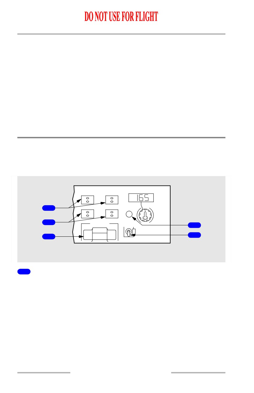
Autopilot / Flight Director
Pushing a CMD or CWS switch engages related A/P in CMD or CWS and
illuminates switch lights. A/P can operate in CMD, CWS, or a combination of
CMD and CWS.
A/P ENGAGE
COURSE
CMD A
CMD B
CWS A
CWS B
1
MA
2
DISENGAGE
F/D
ON
4
5
3
OFF
GLARESHIELD
1
Command Engage (CMD ENGAGE) Switch (A or B):
Push -
• engages A/P
• enables all command modes
• displays CMD in A/P status display
• pushing an engage switch for second A/P, while not in approach mode,
engages second A/P and disengages first A/P
• enables CWS operation
• CWS engages if:
• pitch or roll mode not selected
• pitch or roll mode deselected
• pitch or roll mode manually overridden with control column force.
4.10.16
Automatic Flight -
Controls and Indicators
Boeing 737 Operations Manual
[Option - CWS deactivated on approach]
Note: After localizer and glideslope capture during a dual autopilot approach,
CWS cannot be engaged by manually overriding pitch and roll. Manual
override of autopilots causes autopilot disengagement.
• CWS engaged displays:
• CWS P and/or CWS R in A/P status display
• blank in pitch and/or roll mode FMA
• when approaching a selected altitude in CWS P, the pitch mode engages
in ALT ACQ and ALT HOLD when reaching selected altitude
• when approaching a selected radio course in CWS R with VOR/LOC or
approach mode armed, VOR/LOC engages when course is intercepted
• if pitch is manually overridden while in ALT HOLD and control force is
released within 250 feet of selected altitude, A/P pitch mode engages in
ALT ACQ and returns to selected altitude in ALT HOLD mode.
Note: During F/D only operation while pitch or roll commands are more than 1/2
scale from center, pushing a CMD A or B switch engages the A/P in CWS
for pitch and/or roll and the related F/D bar(s) retract.
2
Control Wheel Steering Engage (CWS ENGAGE) Switch (A or B):
Push -
• engages A/P
• engages pitch and roll modes in CWS. Other pitch and roll modes not
enabled
• displays CWS P and CWS R in A/P status display
• CMD not displayed in A/P status display
• F/Ds, if ON, display guidance commands and FD annunciates in A/P
status display. A/P does not follow commands while in CWS
• A/P pitch and roll controlled by pilot with control wheel pressure
• when control pressure released, A/P holds existing attitude. If aileron
pressure released with 6 degrees or less bank, the A/P rolls wings level
and holds existing heading. Heading hold feature inhibited:
• below 1500 feet RA with gear down
• after LOC capture in APP mode
• after VOR capture with TAS 250 knots or less.
3
Autopilot Disengage (DISENGAGE) Bar
Pull down -
• exposes yellow background
• disengages both A/Ps
• prevents A/P engagement.
4.10.17
Automatic Flight -
Controls and Indicators
Boeing 737 Operations Manual
Lift up -
• conceals yellow background
• enables A/P engagement.
4
Master (MA) Flight Director Indicators (white letters)
If a F/D switch is ON, the light indicates which FCC is controlling the F/D modes.
• illuminated - related FCC is controlling F/D modes.
• extinguished - F/D modes are controlled from opposite FCC
• both lights illuminated - each FCC is controlling modes for related F/D.
5
Flight Director (F/D) Switch
Left F/D switch activates command bars on the Captain’s attitude indicator. Right
F/D switch activates command bars on the First Officer’s attitude indicator.
Left F/D switch activates the command bar on the Captain’s attitude indicator.
Right F/D switch activates the command bar on the First Officer’s attitude
indicator.
ON -
• in flight with A/P ON and F/Ds OFF, turning a F/D switch ON engages
F/D in currently selected A/P modes
• displays FD in A/P status display if A/P is OFF or engaged in CWS
• enables command bar display on related pilot’s attitude indicator
• command bars are displayed if command pitch and/or roll modes are
engaged
• command bars are displayed if command pitch and roll modes are
engaged
• on ground, arms pitch and roll modes for engagement in TO/GA and
wings level when TOGA switch is pushed.
• on ground, arms pitch and roll modes for engagement in TO/GA and
HDG SEL when TOGA switch is pushed.
OFF - command bars retract from related pilot’s attitude indicator.
OFF - command bar retracts from related pilot’s attitude indicator.
4.10.18
Automatic Flight -
Controls and Indicators
Boeing 737 Operations Manual
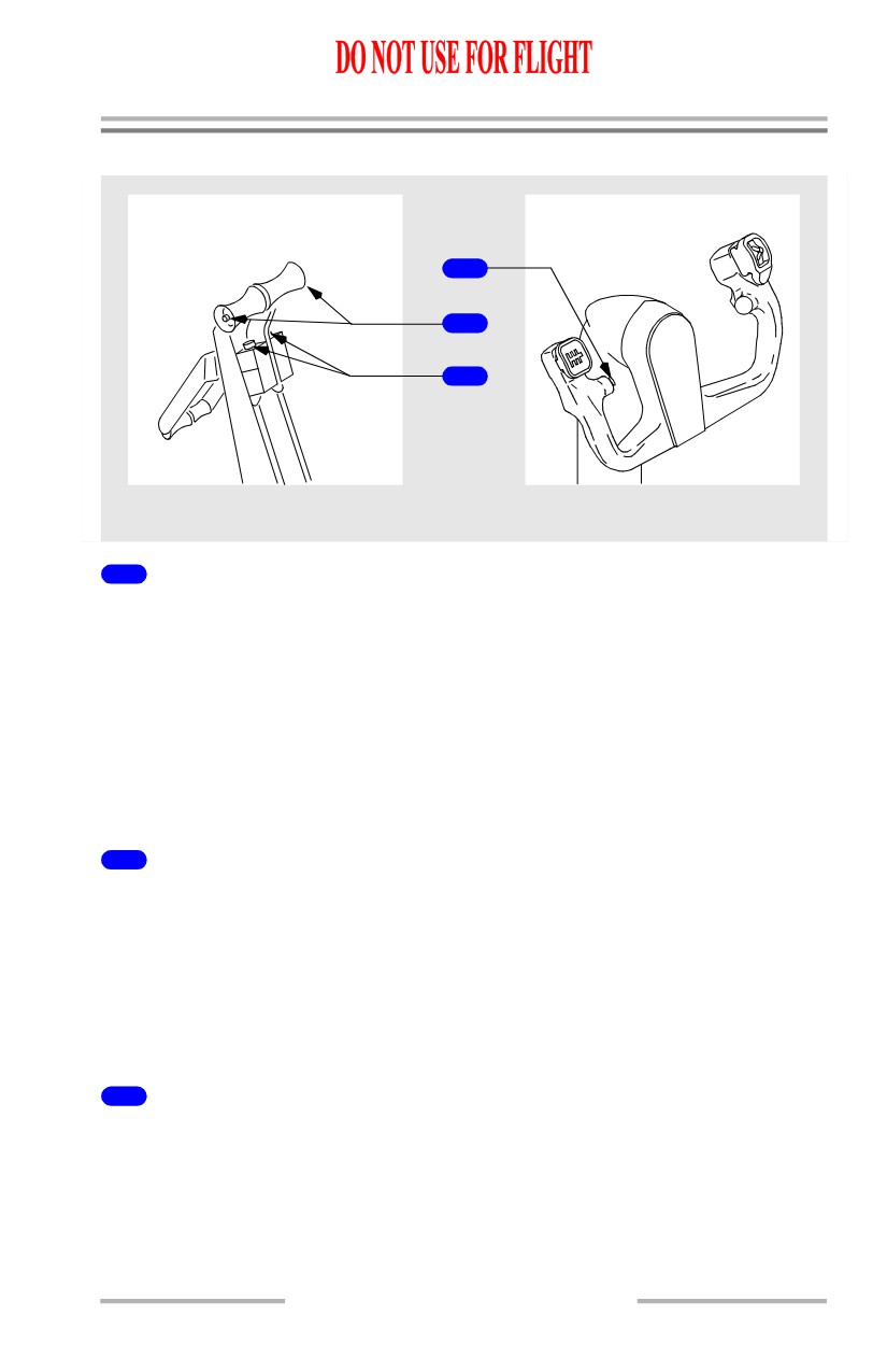
Autopilot / Autothrottle Controls
1
2
3
CONTROL STAND
CONTROL WHEELS
1
Autopilot Disengage Switch
Push -
• disengages both autopilots
• A/P disengage lights flash
• A/P disengage warning tone sounds for a minimum of two seconds
• second push extinguishes disengage lights and silences disengage
warning tone
• if autopilot automatically disengages, extinguishes A/P Disengage lights
and silences A/P warning tone.
2
Autothrottle Disengage Switches
Push -
• disengages autothrottle
• A/T disengage lights flash
• A/T ARM switch trips OFF
• second press extinguishes A/T disengage lights
• extinguishes A/T disengage lights after automatic A/T disengagement.
3
Takeoff/Go-Around (TO/GA) Switches
Push - engages AFDS and A/T in takeoff or go-around mode if previously armed.
4.10.19
Automatic Flight -
Controls and Indicators
Boeing 737 Operations Manual
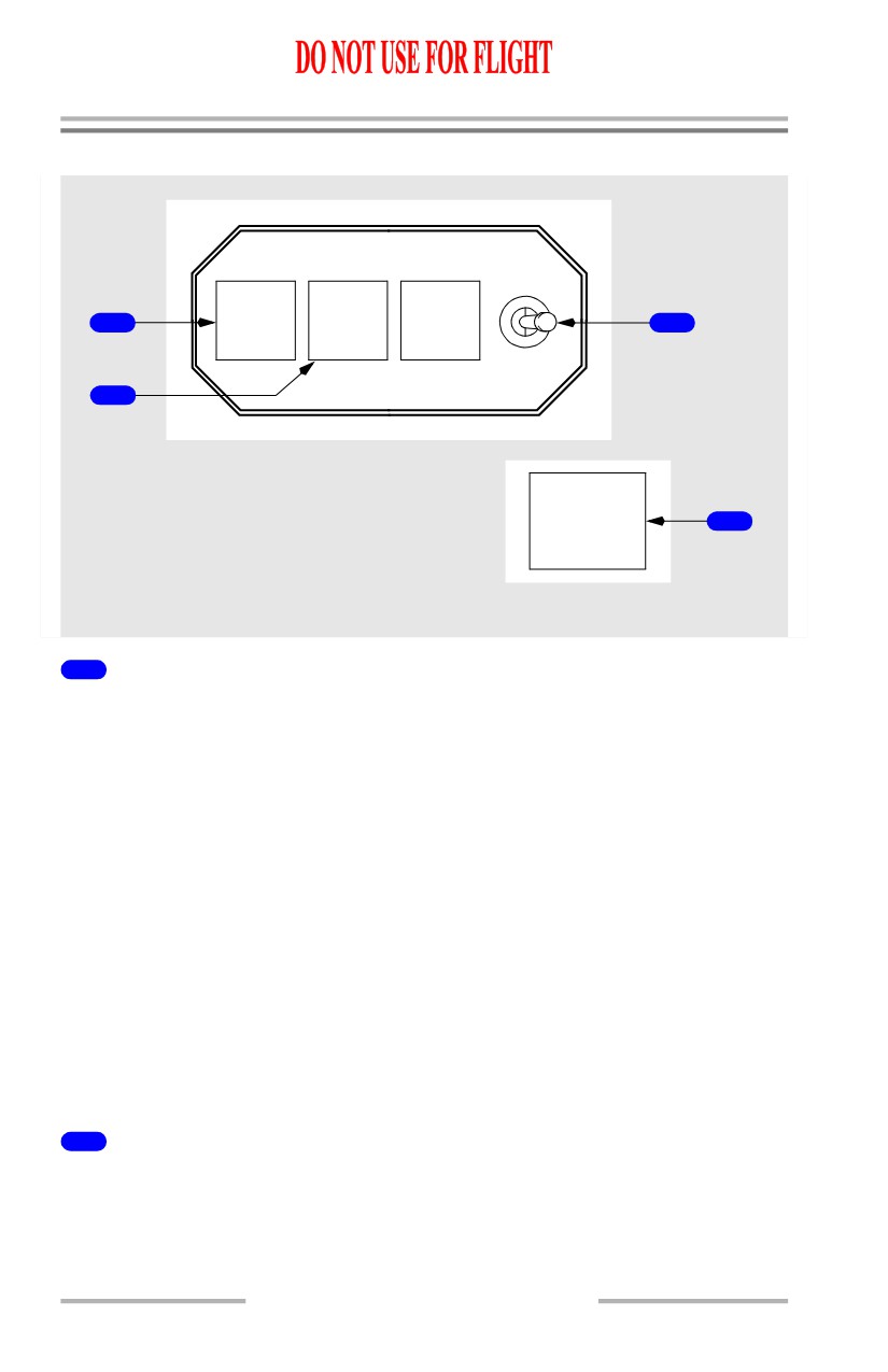
Autopilot / Autothrottle Indicators
1
A/P
A/T
FMC
1
3
P/RST
P/RST
P/RST
2
TEST
2
LEFT FORWARD PANEL
RIGHT FORWARD PANEL
STAB
OUT OF
4
TRIM
LEFT FORWARD PANEL
1
Autopilot (A/P) Disengage Light
Illuminated (red) -
• flashes and tone sounds when autopilot has disengaged
• reset by pushing either disengage light or either A/P disengage switch
• steady for any of following conditions:
• stabilizer out of trim below 800 feet RA on dual channel approach
• ALT ACQ mode inhibited during A/P go-around if stabilizer not
trimmed for single A/P operation
• disengage light test switch held in position 2
• automatic ground system tests fail.
Illuminated (amber) -
• steady - disengage light test switch held in position 1.
[Option - CWS warning activated]
• flashing - A/P automatically reverts to CWS pitch or roll while in CMD.
Resets by pushing either light or selecting another mode.
2
Autothrottle (A/T) Disengage Light
Illuminated (red) -
• flashing - autothrottle has disengaged
• steady - disengage light test switch held in position 2.
4.10.20
Automatic Flight -
Controls and Indicators
Boeing 737 Operations Manual
Illuminated (amber) -
• steady - disengage light test switch held in position 1
[Option - Airspeed deviation warning activated]
• flashing - indicates A/T airspeed error under following conditions:
• inflight
• flaps not up
• airspeed differs from commanded value by +10 or -5 knots and is not
approaching commanded value.
3
Disengage Light Test (TEST) Switch
TEST 1 - illuminates autopilot/autothrottle disengage and FMC alert lights steady
amber.
TEST 2 - illuminates autopilot/autothrottle disengage lights steady red and FMC
alert light steady amber.
Spring-loaded to center position.
4
Stabilizer Out Of Trim (STAB OUT OF TRIM) Light
Operates only with autopilot engaged. Remains extinguished with autopilot not
engaged.
Illuminated (amber) - autopilot not trimming stabilizer properly.
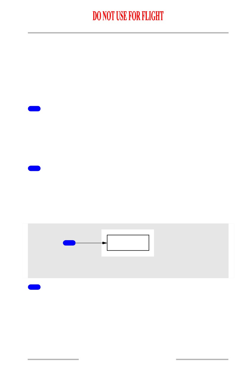
Autoland Warning
[Option]
1
AUTOLAND
LEFT FORWARD PANEL
RIGHT FORWARD PANEL
1
AUTOLAND Warning Light
Armed during dual ILS A/P approach below 500 feet
Flashes (red) if:
• A/P disengages
• stabilizer trim warning occurs
• ILS deviation occurs below 200 feet.
4.10.21
Automatic Flight -
Controls and Indicators
Boeing 737 Operations Manual
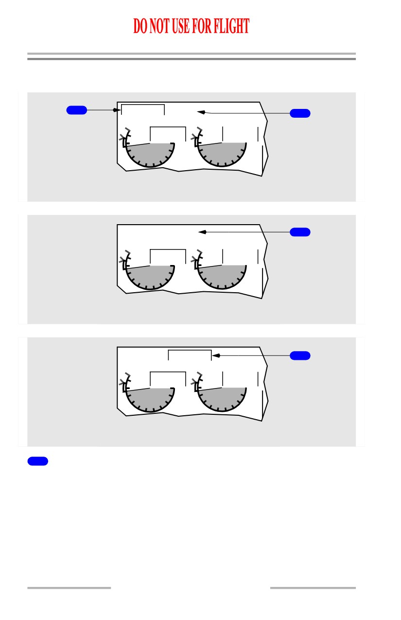
Thrust Mode Display
[Option - Side by side display]
2
A/T LIM
CRZ
TAT-
12
C
1
96.0
96.0
TAI
TAI
87.7
87.7
10
10
0
0
8
8
2
2
6
6
4
4
N
1
UPPER DISPLAY UNIT
[Option - Over/Under display]
TAT-
12
C
CRZ
1
96.0
96.0
TAI
TAI
10
87.7
10
87.7
0
0
8
8
2
2
6
6
4
4
N
1
UPPER DISPLAY UNIT
[Option - Over/Under display]
TAT-
12
C
A/T LIM
2
96.0
96.0
TAI
TAI
10
87.7
10
87.7
0
0
8
8
2
2
6
6
4
4
N
1
UPPER DISPLAY UNIT
1
Thrust Mode Display
N1 limit reference is the active N1 limit for autothrottle and manual thrust control.
N1 limit reference is also displayed by N1 reference bugs with N1 SET control in
AUTO position.
N1 limit reference is normally calculated by the FMC.
Thrust mode display annunciations are:
• TO - takeoff
• R-TO - reduced takeoff
4.10.22
Automatic Flight -
Controls and Indicators
Boeing 737 Operations Manual
• R-CLB - reduced climb
[Option]
• TO B - takeoff bump thrust
• CLB - climb
• CRZ - cruise
• G/A - go-around
• CON - continuous
•
--- - FMC not computing thrust limit.
Note: R-TO does not indicate the type of reduced takeoff. The N1 limit may be
reduced due to the entry of an assumed temperature, a takeoff thrust derate
or a combination of both assumed temperature and takeoff thrust derate.
2
Autothrottle Limit (A/T LIM) Indication
Illuminated (white) - the FMC is not providing the A/T system with N1 limit
values. The A/T is using a degraded N1 thrust limit from the related EEC.
4.10.23
Automatic Flight -
Controls and Indicators
Boeing 737 Operations Manual
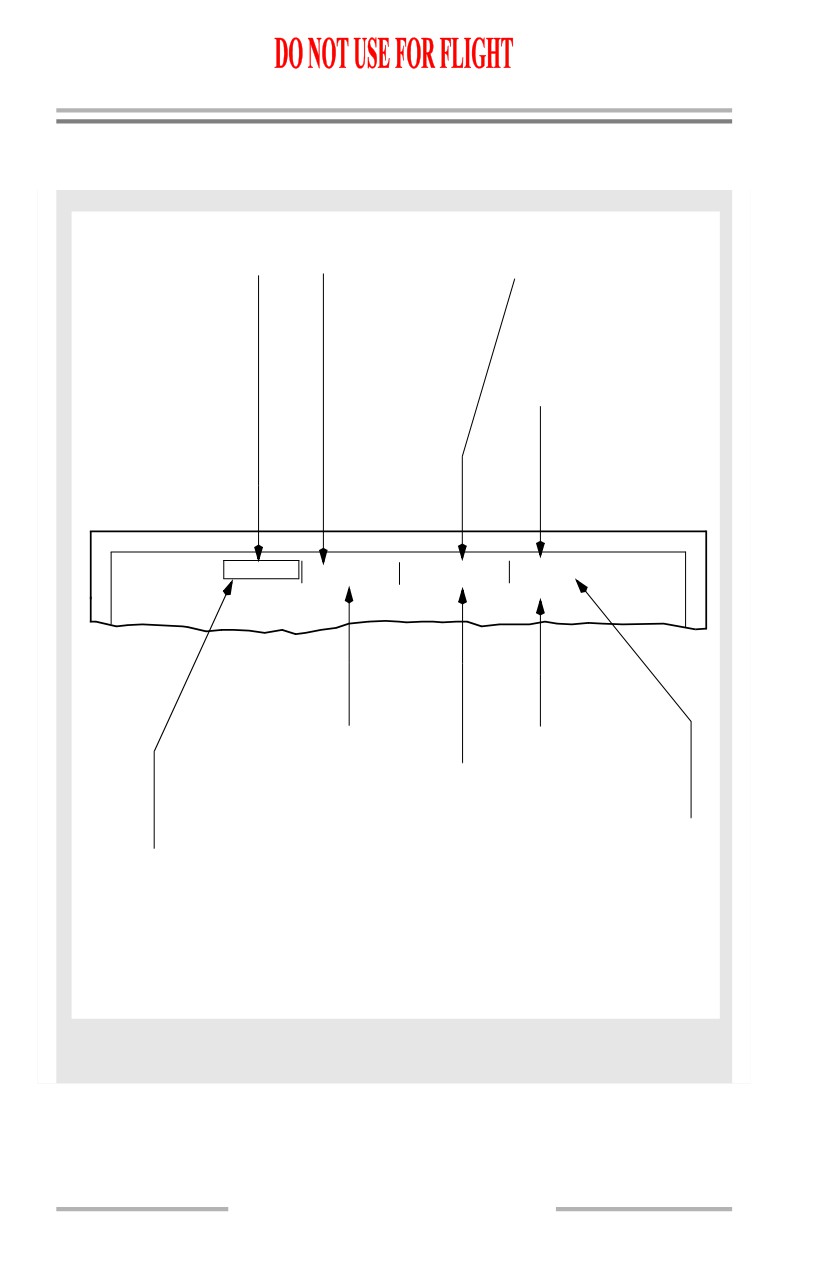
Flight Mode Annunciations (FMAs)
[Option - EFIS/MAP]
A/T ENGAGED MODE
PITCH ENGAGED MODE ROLL ENGAGED MODE
N1
(G)
TO/GA
(G)
HDG SEL (G)
GA
(G)
V/S
(G)
VOR/LOC (G)
RETARD
(G)
ALT ACQ
(G)
LNAV
(G)
FMC SPD (G)
ALT HOLD (G)
MCP SPD (G)
VNAV SPD (G)
THR HLD (G)
VNAV PTH (G)
ARM
(W)
MCP SPD
(G)
A/P STATUS
G/S
(G)
CMD
(G)
FLARE
(G)
FD
(G)
N
1
VNAV PTH
HDG SE L
CMD
G/S
VOR/LOC
CW
S
P
CW
S
R
PITCH ARMED MODE
CWS ROLL ENGAGED
CWS R (Y)
G/S
(W)
V/S
(W)
ROLL ARMED MODE SINGLE CHANNEL
G/S V/S (W)
VOR/LOC (W)
1 CH (Y)
FLARE
(W)
CWS PITCH ENGAGED
CWS P (Y)
MODE CHANGE HIGHLIGHT SYMBOL
A mode change highlight symbol
(rectangle) is drawn around each
(G) - Green
pitch, roll, CWS, and thrust engaged
mode annunciation for a period of 10
(W) - White
seconds after each engagement.
(Y) - Yellow
CAPTAIN’S AND FIRST OFFICER’S
DISPLAY UNITS
4.10.24
Automatic Flight -
Controls and Indicators
Boeing 737 Operations Manual
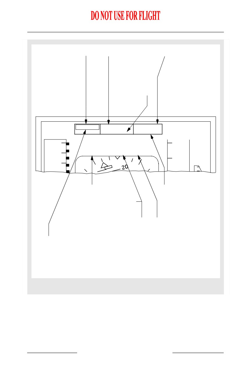
[Option - PFD/ND]
A/T ENGAGED MODE
ROLL ENGAGED MODE
PITCH ENGAGED MODE
N1
(G)
HDG SEL (G)
TO/GA
(G)
GA
(G)
VOR/LOC (G)
V/S
(G)
RETARD
(G)
LNAV
(G)
ALT ACQ
(G)
FMC SPD (G)
ALT HOLD (G)
MCP SPD (G)
VNAV SPD (G)
THR HLD (G)
VNAV PTH (G)
ARM
(W)
MCP SPD
(G)
ROLL ARMED MODE
G/S
(G)
VOR/LOC (W)
FLARE
(G)
N1
HDG SEL
VNAV PTH
VOR/LOC
G/S
.82
31000
360
31400
CWS R CMD CWS P
340
6
CWS ROLL ENGAGED
PITCH ARMED MODE
CWS R (Y)
G/S
(W)
V/S
(W)
A/P STATUS
G/S V/S (W)
CMD
(G)
FLARE
(W)
FD
(G)
SINGLE CHANNEL
CWS PITCH ENGAGED
SINGLE
CWS P (Y)
(Y)
CH
MODE CHANGE HIGHLIGHT SYMBOL
A mode change highlight symbol
(rectangle) is drawn around each
(G) - Green
pitch, roll, CWS, A/P status, and thrust
(W) - White
engaged mode annunciation for a period
of 10 seconds after each engagement.
(Y) - Yellow
OUTER DISPLAY UNITS
4.10.25
Automatic Flight -
Controls and Indicators
Boeing 737 Operations Manual
Intentionally
Blank
4.10.26
Boeing 737 Operations Manual
Automatic Flight
Chapter 4
System Description
Section 20
General
The automatic flight system (AFS) consists of the autopilot flight director system
(AFDS) and the autothrottle (A/T). The flight management computer (FMC)
provides N1 limits and target N1 for the A/T and command airspeeds for the A/T
and AFDS.
The AFDS and A/T are controlled using the AFDS mode control panel (MCP) and
the FMC. Normally, the AFDS and A/T are controlled automatically by the FMC
to fly an optimized lateral and vertical flight path through climb, cruise and
descent.
AFS mode status is displayed on the flight mode annunciation on each pilot’s
primary display.
Autopilot Flight Director System (AFDS)
The AFDS is a dual system consisting of two individual flight control computers
(FCCs) and a single mode control panel.
The two FCCs are identified as A and B. For A/P operation, they send control
commands to their respective pitch and roll hydraulic servos, which operate the
flight controls through two separate hydraulic systems.
For F/D operation, each FCC positions the F/D command bars on the respective
attitude indicator.
MCP Mode Selector Switches
The mode selector switches are pushed to select desired command modes for the
AFDS and A/T. The switch illuminates to indicate mode selection and that the
mode can be deselected by pushing the switch again. While a mode is active,
deselection can be automatically inhibited and is indicated by the switch being
extinguished.
When engagement of a mode would conflict with current AFS operation, pushing
the mode selector switch has no effect. All AFDS modes can be disengaged either
by selecting another command mode or by disengaging the A/P and turning the
F/Ds off.
4.20.1
Automatic Flight -
System Description
Boeing 737 Operations Manual
Autopilot Engagement Criteria
Each A/P can be engaged by pushing a separate CMD or CWS engage switch. A/P
engagement in CMD or CWS is inhibited unless both of the following
pilot-controlled conditions are met:
• no force is being applied to the control wheel
• the STAB TRIM AUTOPILOT cutout switch is at NORMAL.
Only one A/P can be engaged at a given time unless the approach (APP) mode is
engaged. Approach mode allows both A/Ps to be engaged at the same time. Dual
A/P operation provides control through landing flare and touchdown or an
automatic go-around.
In single A/P operation, full automatic flare and touchdown capability and A/P
go-around capability are not available.
Autopilot Disengagement
The A/P automatically disengages when any of the following occurs:
• pushing either A/P disengage switch
• pushing either Takeoff/Go-around (TO/GA) switch with a single A/P
engaged in CWS or CMD below 2000 feet RA
[Option - A/P auto-disengages for TO/GA above 2000 feet RA]
[Option - Honeywell -708 FCC]
• pushing either Takeoff/Go-around (TO/GA) switch with a single A/P
engaged in CWS or CMD above 2000 feet RA with flaps down or G/S
engaged.
• pushing either TO/GA switch after touchdown with both A/Ps engaged in
CMD
• pushing an illuminated A/P ENGAGE switch
• pushing the A/P DISENGAGE bar down
• activating either pilot’s control wheel trim switch
• moving the STAB TRIM AUTOPILOT cutout switch to CUTOUT
• either left or right IRS system failure or FAULT light illuminated
• loss of electrical power or a sensor input which prevents proper operation
of the engaged A/P and mode
• loss of respective hydraulic system pressure.
Note: Loss of the system A engine-driven hydraulic pump, and a heavy demand
on system A, may cause A/P A to disengage.
AFS Failures
Power interruption or loss may cause disengagement of the AFDS and/or A/T.
Re-engagement is possible after power is restored.
4.20.2
Automatic Flight -
System Description
Boeing 737 Operations Manual
Dual channel A/P operation is possible only when two generators are powering the
busses.
Two independent radio altimeters provide radio altitude to the respective FCCs.
With a radio altimeter inoperative, do not use the associated FCC for approach or
landing, and do not use the associated autopilot for approach.
Flight Director Display
Turning a F/D switch ON displays command bars on the respective pilot’s attitude
indicator if command pitch and roll modes are engaged. If command pitch and roll
modes are not engaged, the F/D command bars do not appear. The F/Ds can be
operated with or without the A/P and A/T. F/D command modes can be used with
an A/P engaged in CWS.
F/D commands operate in the same command modes as the A/P except:
• the takeoff mode is a F/D only mode
• dual F/D guidance is available for single engine operation
• the F/D has no landing flare capability. F/D command bars retract from
view at approximately 50 feet RA on an ILS approach.
Normally, FCC A drives the captain’s command bars and FCC B drives the first
officer’s command bars. With both F/D switches ON, the logic for both pilots’ F/D
modes is controlled by the master FCC, and both FMA displays show the same
mode status.
The master FCC is indicated by illumination of the respective master (MA) F/D
indicator light. The master FCC is determined as follows:
• with neither A/P engaged in CMD, the FCC for the first F/D turned on is
the master
• with one or both A/Ps engaged in CMD, the FCC for the first A/P in CMD
is the master FCC, regardless of which F/D is turned on first.
F/D modes are controlled directly from the respective FCC under certain
conditions. This independent F/D operation occurs when neither A/P is engaged
in CMD, both F/D switches are ON and one of the following mode conditions
exists:
• APP mode engaged with LOC and G/S captured
• GA mode engaged and below 400 feet RA
• TO mode engaged and below 400 feet RA.
Independent F/D operation is indicated by illumination of both MA lights. When
independent operation terminates, the MA light extinguishes on the slaved side.
If a generator is lost during a F/D TO or GA, or while in dual F/D APP mode
below 800 feet, the FCC on the unaffected side positions the F/D command bars
on both attitude indicators. If the F/D MA light on the affected side had been
illuminated, it extinguishes upon electrical bus transfer.
4.20.3
Automatic Flight -
System Description
Boeing 737 Operations Manual
AFDS Status Annunciation
The following AFDS status annunciations are displayed in the A/P status display
located above the attitude indicator on the outboard display unit:
• CMD (one or both autopilots are engaged)
• FD (the flight director is ON and the autopilot is either OFF or engaged in
CWS)
• CWS P (pitch mode engaged in CWS)
• CWS R (roll mode engaged in CWS)
[Option - EFIS/MAP]
•
1 CH (for single A/P ILS approach, annunciates after localizer capture
and remains on for entire approach. For dual A/P ILS approach,
annunciates after localizer capture and extinguishes after pitch monitor
confidence test is successfully completed).
[Option - PFD/ND]
• SINGLE CH (for single A/P ILS approach, annunciates after localizer
capture and remains on for entire approach. For dual A/P ILS approach,
annunciates after localizer capture and extinguishes after pitch monitor
confidence test is successfully completed).
AFDS Flight Mode Annunciations
The flight mode annunciations are displayed just above the attitude indicator on
the outboard display unit. The mode annunciations, from left to right, are:
[Option - EFIS/MAP]
• autothrottle
• pitch
• roll.
[Option - PFD/ND]
• autothrottle
• roll
• pitch.
Engaged or captured modes are shown at the top of the flight mode annunciation
boxes in large green letters. Armed modes are shown in smaller white letters at the
bottom of the flight mode annunciation boxes.
Autothrottle Modes
• N1 - the autothrottle maintains thrust at the selected N1 limit displayed
on the thrust mode display
• GA - the autothrottle maintains thrust at reduced go-around setting or full
go-around N1 limit
• RETARD - displayed while autothrottle moves thrust levers to the aft
stop. RETARD mode is followed by ARM mode
4.20.4
Automatic Flight -
System Description
Boeing 737 Operations Manual
• FMC SPD - the autothrottle maintains speed commanded by the FMC.
The autothrottle is limited to the N1 value shown on the thrust mode
display
• MCP SPD - the autothrottle maintains speed set in the MCP IAS/MACH
display. The autothrottle is limited to the N1 value shown on the thrust
mode display
• THR HLD - the thrust lever autothrottle servos are inhibited; the pilot can
set the thrust levers manually
• ARM - no autothrottle mode engaged. The thrust lever autothrottle servos
are inhibited; the pilot can set thrust levers manually.
Pitch Modes
• TO/GA - Takeoff
Engaged for takeoff by turning both F/D switches ON and pushing either
TO/GA switch. Both F/Ds must be ON to engage TO/GA prior to starting
takeoff.
The AFDS commands pitch attitude in the following order:
•
10 degrees nose down until 60 knots IAS
•
15 degrees nose up after 60 knots IAS
•
15 degrees nose up after lift-off until a sufficient climb rate is
acquired. Then, pitch is commanded to maintain MCP speed plus 20
knots.
TO/GA can also be engaged for takeoff with F/D switches OFF if a
TO/GA switch is pushed after 80 knots IAS below 2000 feet AGL and
prior to 150 seconds after lift-off.
• TO/GA - Go-around
Engaged for go-around by pushing the TO/GA switch under the
following conditions:
• inflight below 2000 feet radio altitude
[Option - A/P auto-disengages for TO/GA above 2000 feet RA]
[Option - Honeywell -708 FCC]
• inflight above 2000 feet radio altitude with flaps down or G/S
captured
• not in takeoff mode
• either F/D ON or OFF.
4.20.5
Automatic Flight -
System Description
Boeing 737 Operations Manual
The F/Ds command 15 degrees nose up pitch and roll to hold the
approach ground track at time of go-around engagement. After
reaching a programmed rate of climb, pitch commands the target
airspeed for each flap setting based on maximum takeoff weight
calculations.
•
VNAV -
VNAV is engaged by pushing the VNAV switch. With a VNAV mode
engaged, the FMC commands AFDS pitch and A/T modes to fly the
vertical profile.
• VNAV SPD - the AFDS maintains the FMC speed displayed on the
airspeed indicator and/or the CDU CLIMB or DESCENT pages
• VNAV PTH - the AFDS maintains FMC altitude or descent path with
pitch commands.
•
V/S (engaged) - commands pitch to hold selected vertical speed
•
V/S (armed) - V/S mode can be engaged by moving Vertical Speed
thumbwheel
•
ALT ACQ - transition maneuver entered automatically from a V/S, LVL
CHG, or VNAV climb or descent to selected MCP altitude. Engages but
does not annunciate during VNAV transition
•
ALT HOLD - commands pitch to hold MCP selected altitude or
uncorrected barometric altitude at which ALT HOLD switch was pushed
•
MCP SPD - pitch commands maintain IAS/MACH window airspeed or
Mach
•
G/S (armed) - the AFDS is armed for G/S capture
•
G/S (engaged) - the AFDS follows the ILS glideslope
•
FLARE (armed) - during a dual A/P ILS approach, FLARE is displayed
after LOC and G/S capture and below 1500 feet RA. The second A/P
couples with the flight controls and A/P go-around mode arms
•
FLARE (engaged) - during a dual A/P ILS approach, flare engages at 50
feet radio altitude. FLARE accomplishes the autoland flare maneuver.
Roll Modes
• LNAV - the AFDS intercepts and tracks the active FMC route. Either of
the following capture criteria must be met:
• on any heading and within 3 NM of the active route segment
• if outside of 3 NM of active route segment, airplane must be on an
intercept course of 90 degrees or less and intercept the route segment
before the active waypoint.
• HDG SEL - the airplane is turning to, or is on the heading selected in the
MCP Heading Display
• VOR/LOC (armed) - AFDS is armed to capture selected VOR or LOC
COURSE
• VOR/LOC (engaged) - AFDS tracks selected VOR course or tracks
selected localizer course along the inbound front course bearing.
4.20.6
Automatic Flight -
System Description
Boeing 737 Operations Manual
Autopilot Control Wheel Steering
CWS Engage Switch Selected
Pushing a CWS engage switch engages the A/P pitch and roll axes in the CWS
mode and displays CWS P and CWS R on the FMAs.
With CWS engaged, the A/P maneuvers the airplane in response to control
pressures applied by either pilot. The control pressure is similar to that required
for manual flight. When control pressure is released, the A/P holds existing
attitude.
If aileron pressure is released with 6 degrees or less bank, the A/P rolls the wings
level and holds existing heading. This heading hold feature with bank less than 6
degrees is inhibited when any of the following conditions exists:
• below 1,500 feet RA with the landing gear down
• after F/D VOR capture with TAS 250 knots or less
• after F/D LOC capture in the APP mode.
Pitch CWS with a CMD Engage Switch Selected
The pitch axis engages in CWS while the roll axis is in CMD when:
• a command pitch mode has not been selected or was deselected
• A/P pitch has been manually overridden with control column force. The
force required for override is greater than normal CWS control column
force. This manual pitch override is inhibited in the APP mode with both
A/Ps engaged.
CWS P is annunciated on the FMAs while this mode is engaged. Command pitch
modes can then be selected.
When approaching a selected altitude in CWS P with a CMD engage switch
selected, CWS P changes to ALT ACQ. When at the selected altitude, ALT HOLD
engages.
If pitch is manually overridden while in ALT HOLD at the selected altitude, ALT
HOLD changes to CWS P. If control force is released within 250 feet of the
selected altitude, CWS P changes to ALT ACQ, the airplane returns to the selected
altitude, and ALT HOLD engages. If the elevator force is held until more than 250
feet from the selected altitude, pitch remains in CWS P.
Roll CWS with a CMD Engage Switch Selected
The roll axis engages in CWS while the pitch axis is in CMD when:
• a command roll mode has not been selected or was deselected
• A/P roll has been manually overridden with control wheel force. The
force required for override is greater than the normal CWS control wheel
force.
CWS R is annunciated on the FMAs while this mode is engaged.
4.20.7