Boeing 737 - 600/700/800/900. Operations Manual (1997 year) - page 36
Engines, APU -
Over/Under - Displays
Boeing 737 Operations Manual
2
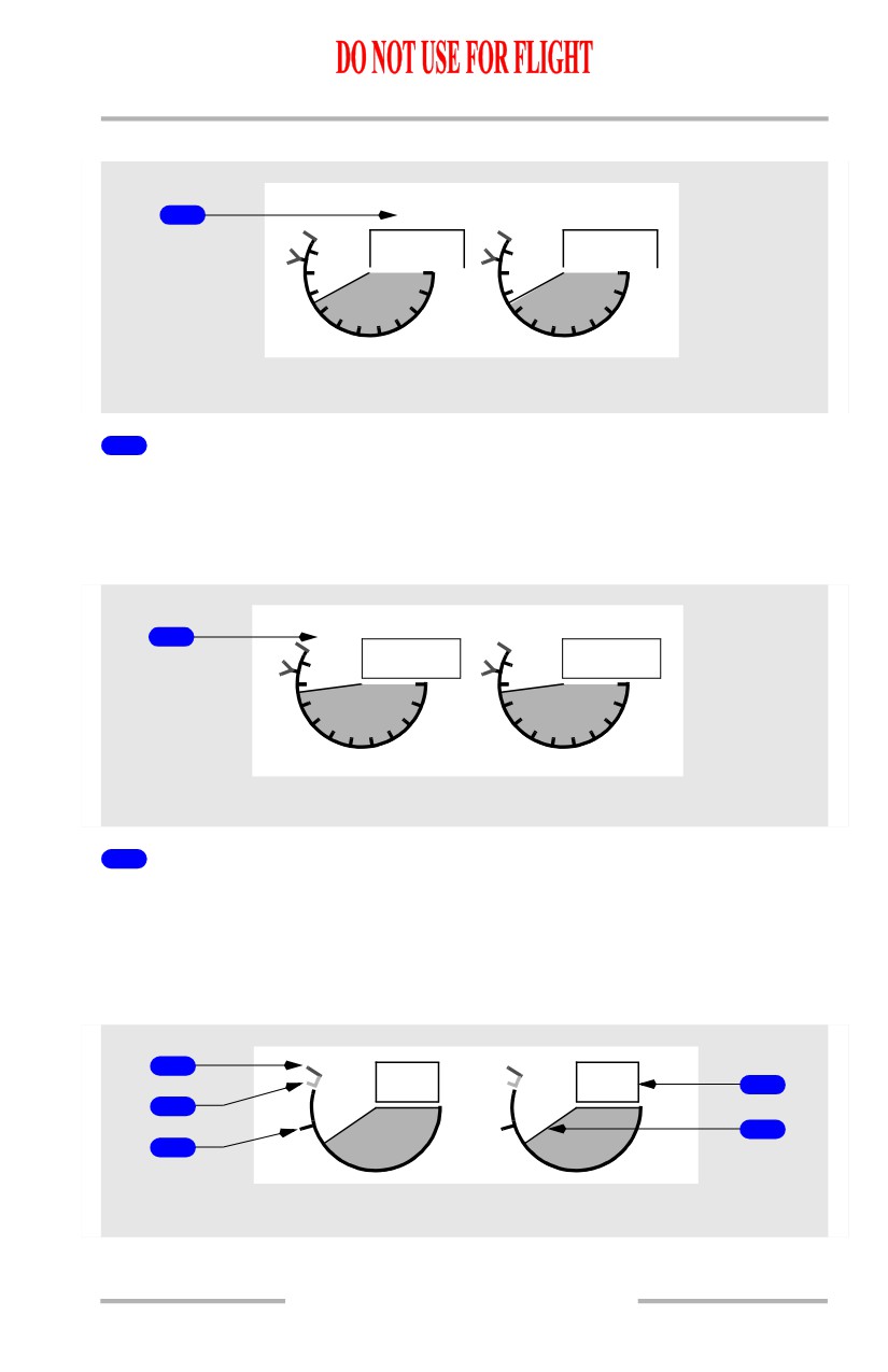
N1 SET Inner Knob (spring-loaded to center)
Rotate - positions reference N1 bug(s) and readouts when N1 SET outer knob is
set to BOTH, 1, or 2.
3
Reference N1 Bugs
Displayed (green) - with N1 SET outer knob in AUTO, 1, 2 or BOTH position.
4
N1 Redlines
Displayed (red) - N1% RPM operating limit
5
N1 Command Sectors
Displayed
(white)
- momentary difference between actual N1 and value
commanded by thrust lever position.
6
N1 RPM Readouts (digital)
Displayed (white) - normal operating range.
Displayed (red) -
• operating limit exceeded
• on ground after engine shutdown, red box indicates an inflight
exceedance has occurred.
7
Reference N1 Readouts
Displayed (green) - manually set N1% RPM:
• set with N1 SET inner knob when N1 SET is in BOTH, 1, or 2 position
• blank when N1 SET outer knob in AUTO position
•
- - - - when N1 SET outer knob in Auto and FMC source invalid.
8
N1 RPM Indications
Displays N1% RPM:
• displayed (white) - normal operating range
• displayed (red) - operating limit exceeded.
7.11.4
Engines, APU -
Over/Under - Displays
Boeing 737 Operations Manual
Thrust Reverser Indications
1
REV
REV
75.3
75.3
10
10
0
0
8
8
2
2
6
6
4
4
N1
UPPER DISPLAY UNIT
1
Thrust Reverser (REV) Indications
Displayed (amber) - thrust reverser is moved from stowed position.
Displayed (green) - thrust reverser is deployed.
Thermal Anti-Ice Indication
1
TAI
TAI
87.7
87.7
10
10
0
0
8
8
2
2
6
6
4
4
N1
UPPER DISPLAY UNIT
1
Thermal Anti-Ice (TAI) Indications
Displayed (green) - cowl anti-ice valve(s) open.
Displayed (amber) - cowl anti-ice valve is not in position indicated by related
engine anti-ice switch.
EGT Indications
1
663
663
4
2
5
3
EGT
UPPER DISPLAY UNIT
7.11.5
Engines, APU -
Over/Under - Displays
Boeing 737 Operations Manual
1
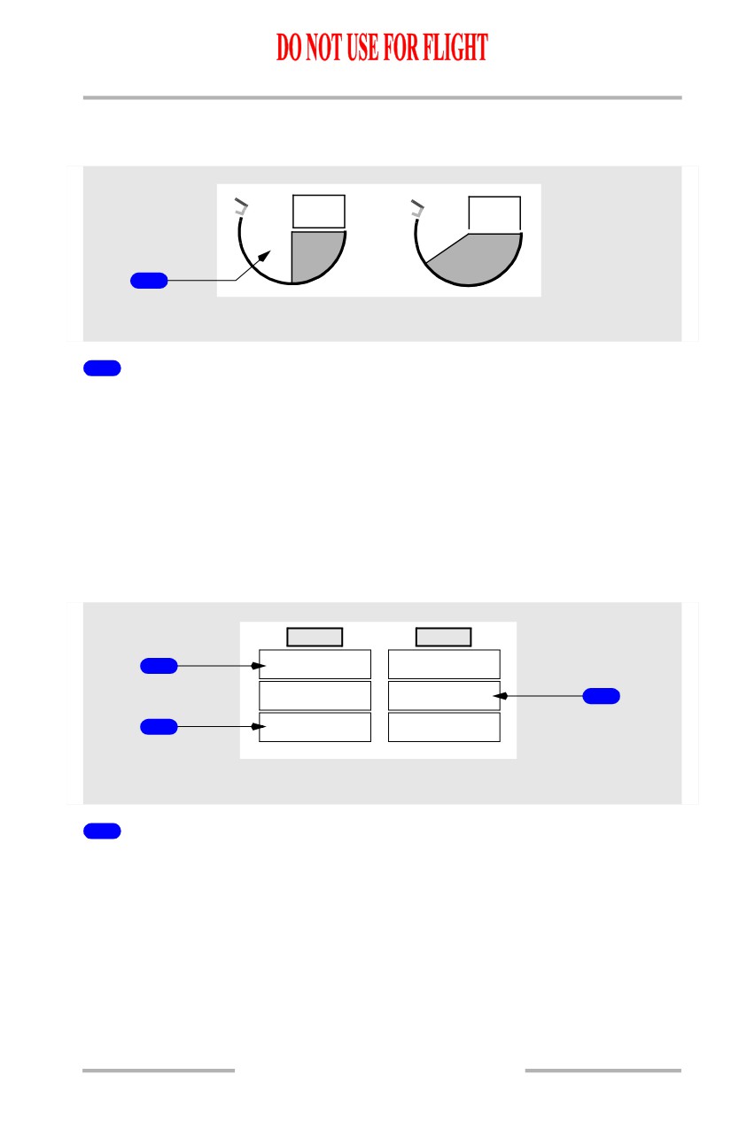
Exhaust Gas Temperature (EGT) Redlines
Displayed (red) - maximum takeoff EGT limit.
2
Exhaust Gas Temperature (EGT) Amber Bands
Displayed (amber) - lower end of band displays maximum continuous EGT limit.
3
Exhaust Gas Temperature (EGT) Start Limit Lines
Displayed (red) - N2 less than 50%.
4
Exhaust Gas Temperature (EGT) Readouts (digital)
Displayed (white) - normal operating range (degrees C)
[Option - Color change inhibit 5 minutes]
Displayed (amber) - maximum continuous limit exceeded; color change inhibited
for up to 5 minutes during takeoff or go-around
[Option - Color change inhibit 10 minutes]
Displayed (amber) - maximum continuous limit exceeded
• Color change inhibited for up to 5 minutes during takeoff or go-around
(normal operation)
• color change inhibited for up to 10 minutes during takeoff or go-around
(when an engine out condition occurs within the first 5 minutes of the
inhibit)
Displayed (red) - maximum takeoff limit or start limit exceeded
On ground, after engine shutdown, red box indicates an exceedance has occurred
EEC senses conditions that may lead to hot start during ground starts (blinking
white box).
5
Exhaust Gas Temperature (EGT) Indications
Displayed (white) - normal operating range.
[Option - Color change inhibit 5 minutes]
Displayed (amber) - maximum continuous limit exceeded; color change inhibited
for up to 5 minutes during takeoff or go-around
[Option - Color change inhibit 10 minutes]
Displayed (amber) - maximum continuous limit exceeded
• color change inhibited for up to 5 minutes during takeoff or go-around
(normal operation)
• color change inhibited for up to 10 minutes during takeoff or go-around
(when an engine out condition occurs within the first 5 minutes of the
inhibit)
7.11.6
Engines, APU -
Over/Under - Displays
Boeing 737 Operations Manual
Displayed (red) - maximum takeoff limit or start limit exceeded.
Engine Fail Alert
467
663
ENG
FAIL
1
EGT
UPPER DISPLAY UNIT
1
Engine Fail (ENG FAIL) Alert
Displayed (amber) -
• engine operating below sustainable idle (less than 50% N2); and
• engine start lever in IDLE position.
Alert remains until -
• engine recovers; or
• start lever moved to CUTOFF; or
• engine fire warning switch pulled.
Crew Alerts
ENG 1
ENG 2
START VALVE
START VALVE
1
OPEN
OPEN
OIL FILTER
OIL FILTER
3
BYPASS
BYPASS
LOW OIL
LOW OIL
2
PRESSURE
PRESSURE
UPPER DISPLAY UNIT
1
START VALVE OPEN Alert
Illuminated (amber) -
• steady - respective engine start valve open and air is supplied to starter
• blinking - uncommanded opening of start valve. Alert is displayed and
solid amber boxes are displayed in unannunciated positions for that
engine. All three boxes blink for ten seconds, then alert remains on steady
and solid amber boxes are removed (see Note).
7.11.7
Engines, APU -
Over/Under - Displays
Boeing 737 Operations Manual
2
LOW OIL PRESSURE Alert
Illuminated (amber) -
• steady - oil pressure at or below red line
• blinking - with a condition of low oil pressure. Alert is displayed and
solid amber boxes are displayed in unannunciated positions for that
engine. All three boxes blink for ten seconds, then alert remains on steady
and solid amber boxes are removed (see Note).
3
OIL FILTER BYPASS Alert
Illuminated (amber) -
• steady - indicates an impending bypass of scavenge oil filter
• blinking - with an impending bypass. Alert is displayed and solid amber
boxes are displayed in unannunciated positions for that engine. All three
boxes blink for ten seconds, then alert remains on steady and solid amber
boxes are removed (see Note).
Note: Blinking is inhibited:
• during takeoff from 80 knots to 400 feet RA, or 30 seconds after reaching
80 knots, whichever occurs first
• during landing below 200 feet RA until 30 seconds after touchdown
• during periods when blinking is inhibited, alerts illuminate steady.
7.11.8
Engines, APU -
Over/Under - Displays
Boeing 737 Operations Manual
Secondary Engine Indications
[Option - Over/Under display, kgs]
81.1
81.1
3.90
3.90
36
41
1
120
120
LO
3
15
1.6
4.5
LOWER DISPLAY UNIT
1
Secondary Engine Indications
Secondary engine indications are displayed:
• when CDS initially receives power
• when selected by the Multi-Function Display (MFD)
• in flight when an engine start lever moved to CUTOFF
• in flight when an engine fails
• when a secondary engine parameter exceeds normal operating range.
7.11.9
Engines, APU -
Over/Under - Displays
Boeing 737 Operations Manual
N2 Indications
1
81.1
81.1
3
2
N
2
LOWER DISPLAY UNIT
1
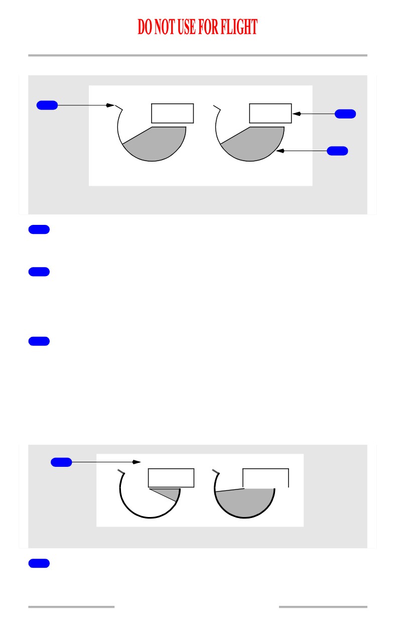
N2 Redlines
Displayed (red) - N2% RPM operating limit.
2
N2 RPM Indications
Displays N2% RPM
• displayed (white) - normal operating range
• displayed (red) - operating limit exceeded.
3
N2 Readouts (digital)
Displayed (white) - normal operating range.
Displayed (red) -
• operating limit exceeded
• on ground, after engine shutdown, red box indicates an inflight
exceedance has occurred.
Crossbleed Start Indication
1
X-BLD
12.7
87.6
N2
LOWER DISPLAY UNIT
1
Crossbleed Start (X-BLD) Indication
Displayed (magenta) - crossbleed air recommended for inflight start.
7.11.10
Engines, APU -
Over/Under - Displays
Boeing 737 Operations Manual
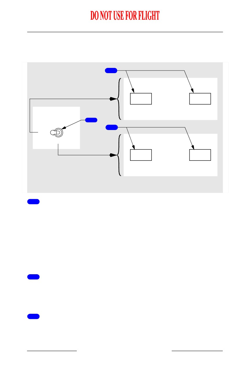
Displayed when airspeed is less than required for a windmilling start.
Fuel Flow/Fuel Used Indications
[Option - Over/Under display, kgs]
2
3.90
FF
3.90
FUEL FLOW
1
RESET
3
RATE
USED
5.36
FF
5.36
CENTER
FORWARD PANEL
LOWER DISPLAY UNIT
1
FUEL FLOW Switch (spring-loaded to RATE)
RATE - displays fuel flow to engine.
USED -
• displays fuel used since last reset
• after 10 seconds, display automatically reverts to fuel flow.
RESET -
• resets fuel used to zero
• displays fuel used for 1 second, decreases to zero, then displays fuel flow.
2
Fuel Flow (FF) Readout (digital)
[Option - kgs]
Displayed (white) - fuel flow to engine with FUEL FLOW switch in RATE
position (kilograms per hour x 1000).
3
Fuel Used Readout (digital)
Illuminated (white) - displayed when FUEL FLOW switch moved to USED or
RESET.
7.11.11
Engines, APU -
Over/Under - Displays
Boeing 737 Operations Manual
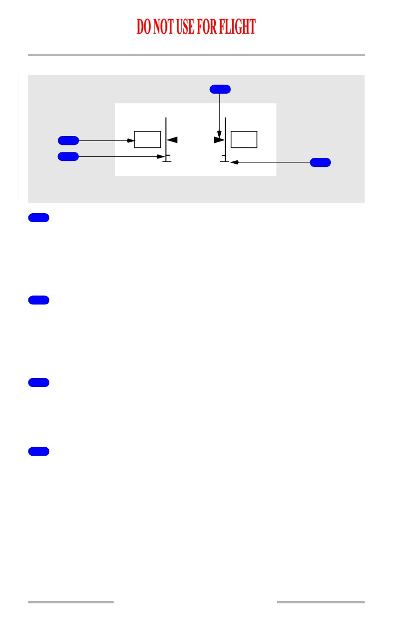
Oil Pressure Indications
2
OIL
1
45
45
PRESS
3
4
LOWER DISPLAY UNIT
1
Oil Pressure (OIL PRESS) Readout
Displays engine oil pressure (psi)
• displayed (white) - normal operating range
• displayed (amber) - caution range
• displayed (red) - operating limit reached.
2
Oil Pressure (OIL PRESS) Pointer
Displays engine oil pressure:
• displayed (white) - normal operating range
• displayed (amber) - caution range reached
• displayed (red) - operating limit reached.
3
Low Oil Pressure (OIL PRESS) Amber Band
Displayed (amber) - low oil pressure caution range beginning at red line.:
• variable depending on N2% RPM above 65% N2
• amber band not displayed below 65% N2.
4
Low Oil Pressure (OIL PRESS) Redline
Displayed (red) - oil pressure operating limit.
7.11.12
Engines, APU -
Over/Under - Displays
Boeing 737 Operations Manual
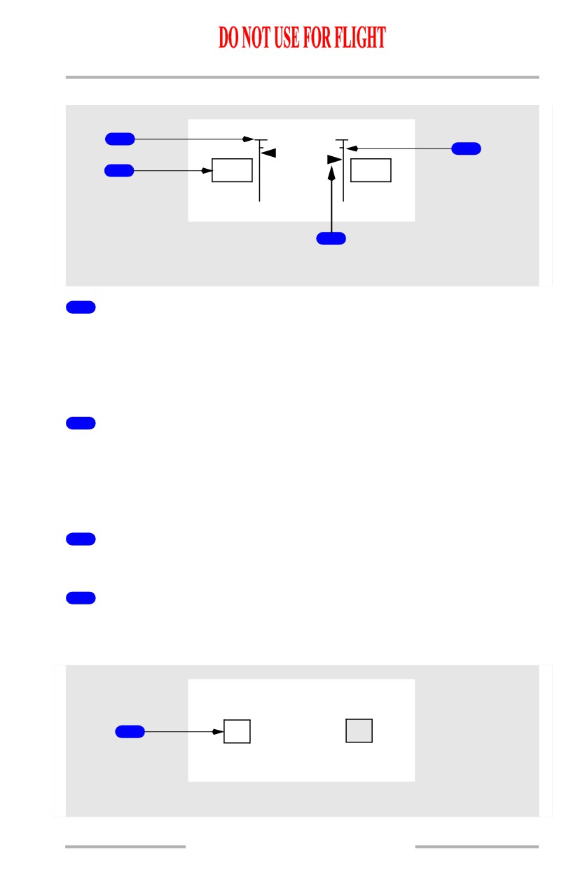
Oil Temperature Indications
4
3
OIL
1
125
120
TEMP
2
LOWER DISPLAY UNIT
1
Oil Temperature (OIL TEMP) Readout
Displays oil temperature (degrees C):
• displayed (white) - normal operating range
• displayed (amber) - caution range reached
• displayed (red) - operating limit reached.
2
Oil Temperature (OIL TEMP) Pointer
Displays oil temperature (degrees C):
• displayed (white) - normal operating range
• displayed (amber) - caution range reached
• displayed (red) - operating limit reached.
3
High Oil Temperature (OIL TEMP) Amber Band
Displayed (amber) - oil temperature caution range.
4
High Oil Temperature (OIL TEMP) Redline
Displayed (red) - oil temperature operating limit.
Oil Quantity Indications
1
15
OIL QTY
3
LO
LOWER DISPLAY UNIT
7.11.13
Engines, APU -
Over/Under - Displays
Boeing 737 Operations Manual
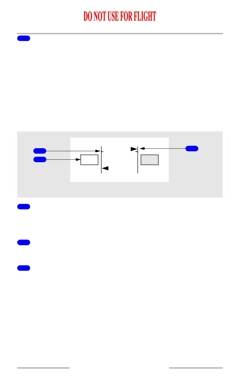
1
Oil Quantity (OIL QTY) Readout
[Option - liters]
Displays usable oil quantity in liters.
Video is reversed and LO (white) displayed for low oil quantity.
Note: Indicated oil quantity may decrease significantly during engine start,
takeoff and climb out. If this occurs, engine operation is not impacted and
the correct oil quantity should be indicated during level flight.
Note: An oil quantity indication as low as zero is normal if windmilling N2 RPM
is below approximately 8%.
Engine Vibration Indications
3
2
1
1.2
VIB
4.5
LOWER DISPLAY UNIT
1
Vibration (VIB) Readout
Displayed (white) - engine vibration level.
Video is reversed for high vibration.
2
High Limit
Displays tick mark and thick line.
3
Vibration (VIB) Pointer
Displayed (white) - engine vibration level.
7.11.14
Engines, APU -
Over/Under - Displays
Boeing 737 Operations Manual
Compact Engine Displays
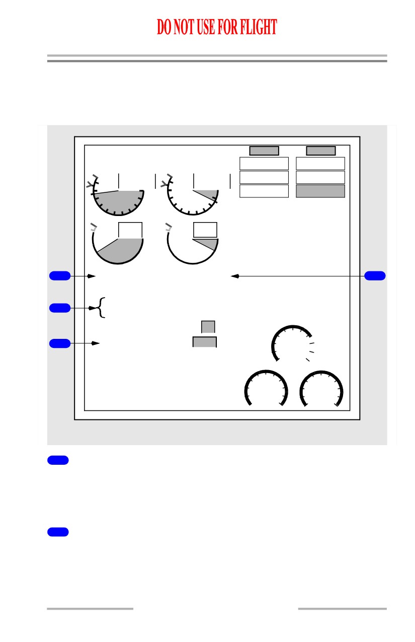
The following changes occur to the secondary engine display in the compact
engine displays.
[Option - kgs]
TAT
-12c R-TO
+42c
ENG 1
ENG 2
START VALVE
START VALVE
OPEN
OPEN
96.0
96.0
TAI
TAI
OIL FILTER
OIL FILTER
87.7
12.7
BYPASS
BYPASS
10
10
LOW OIL
LOW OIL
0
0
PRESSURE
PRESSURE
8
8
2
2
6
6
4
4
N
1
663
113
EGT
1
81.6
N
2
10.6
XB
4
3.80
FF
0.00
36
OIL PRESS
20
2
120
OIL TEMP
105
14
OIL QTY
3
LO
CTR
3
1.2
VIB
4.5
7600
FUEL
KG
1
2
3800
3800
UPPER OR LOWER DISPLAY UNIT
1
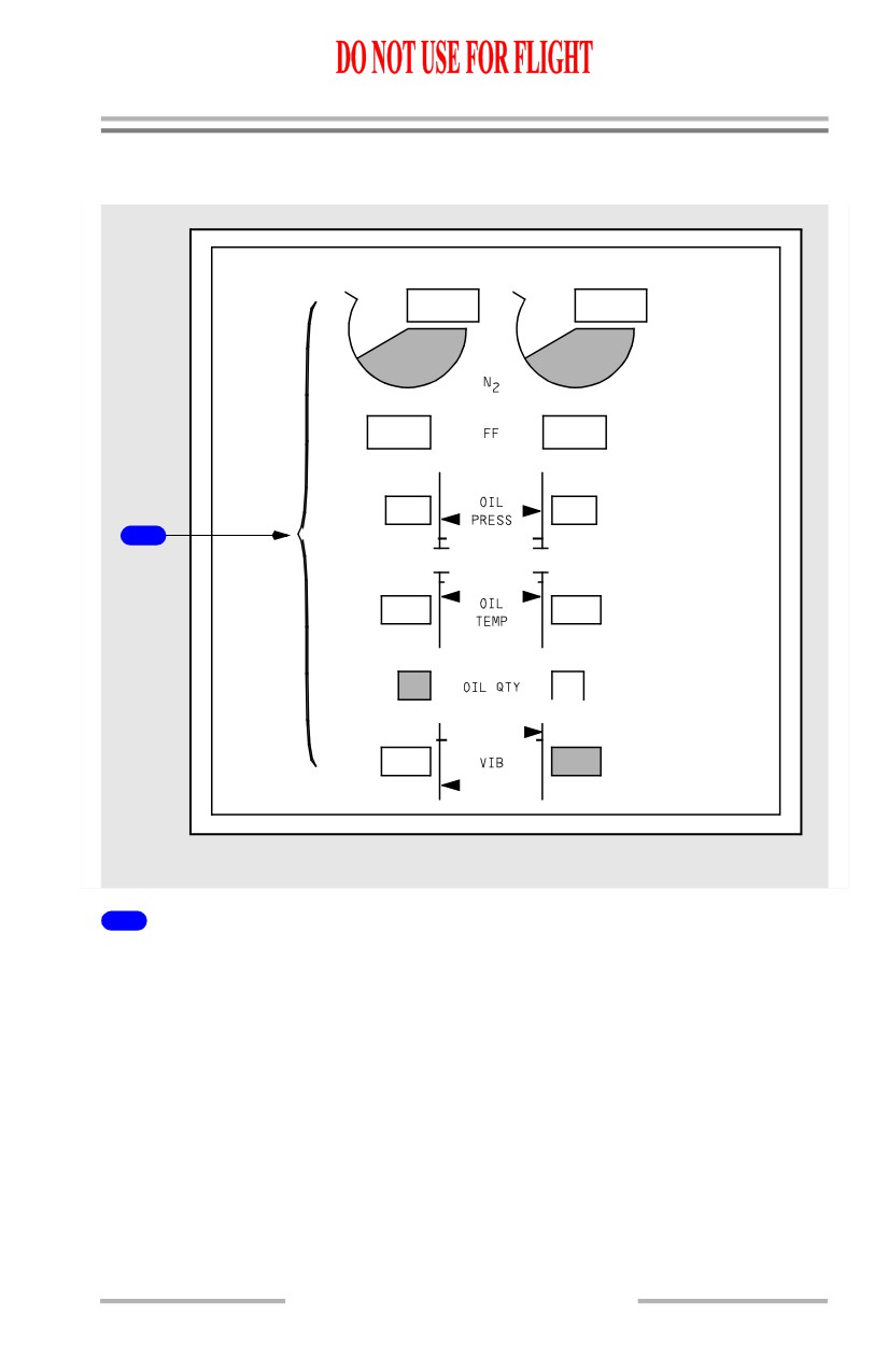
N2 RPM Indications
N2 changes from round dial display to a digital display.
The digital display is framed by a red box after engine shutdown on the ground if
an inflight exceedance occurred.
2
OIL PRESS, OIL TEMP Indications
Displayed as digital readouts only
The digital readouts display amber or red if limits are exceeded.
7.11.15
Engines, APU -
Over/Under - Displays
Boeing 737 Operations Manual
3
Vibration (VIB) Indications
Displayed as digital readout only.
4
Crossbleed Start (XB) Indications
Displayed on the side of N2
7.11.16
Boeing 737 Operations Manual
Engines, APU
Chapter 7
General Controls and Indicators
Section 15
Engine Start Switches
[Option - Without automatic ignition]
ENGINE START
GRDOFF CONT
GRDOFF CONT
BOTH
FLT
FLT
IGN
IGN
L
R
1
2
1
2
FORWARD OVERHEAD PANEL
[Option - With automatic ignition]
ENGINE START
GRDAUTOCONT
GRDAUTOCONT
BOTH
FLT
FLT
IGN
IGN
1
L
R
2
1
2
FORWARD OVERHEAD PANEL
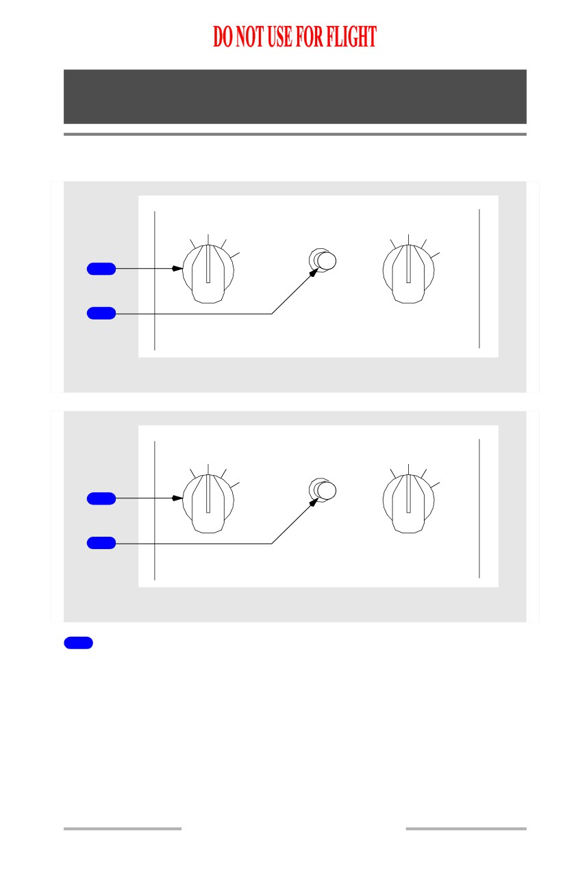
1
ENGINE START Switches
GRD -
• opens start valve
• closes engine bleed valve
• for ground starts, arms selected igniter(s) to provide ignition when engine
start lever is moved to IDLE
• for inflight starts, arms both igniters to provide ignition when engine start
lever is moved to IDLE
[Option - Without automatic ignition]
• releases to OFF at start valve cutout.
7.15.1
Engines, APU -
General Controls and Indicators
Boeing 737 Operations Manual
[Option - With automatic ignition]
• releases to AUTO at start valve cutout.
[Option - Without automatic ignition]
OFF -
• ignition normally off
• both igniters are activated when engine start lever is in IDLE and:
• an uncommanded rapid decrease in N2 occurs or,
• N2 is between 57% and 50% or,
• in flight - N2 is between idle and 5%.
[Option - With automatic ignition]
AUTO -
• ignition normally off
• both igniters are activated when engine start lever is in IDLE and:
• an uncommanded rapid decrease in N2 occurs or,
• N2 is between 57% and 50% or,
• in flight - N2 is between idle and 5%.
• provides automatic ignition to selected igniters when:
• engine is running and,
• flaps are not up below 18000 feet altitude or,
• engine anti-ice is selected to ON.
CONT -
• provides ignition to selected igniters when engine is operating and engine
start lever is in IDLE
• in flight - provides ignition to both igniters when N2 is below idle and
engine start lever is in IDLE.
FLT - provides ignition to both igniters when engine start lever is in IDLE.
2
Ignition Select Switch
IGN L - selects the left igniter for use on both engines.
BOTH - selects both igniters for use on both engines.
IGN R - selects the right igniter for use on both engines.
7.15.2
Engines, APU -
General Controls and Indicators
Boeing 737 Operations Manual
Engine Display Control Panel
[Option - Side by side display]
N1 SET
SPD REF
AUTO
AUTO
1
BOTH
1
V1
2
SET
VR
WT
3
VREF
FUEL FLOW
MFD
RESET
2
INOP
INOP
RATE
USED
CENTER FORWARD PANEL
[Option - Over/Under display]
N1 SET
SPD REF
AUTO
AUTO
3
1
1
BOTH
V1
2
SET
VR
WT
VREF
4
FUEL FLOW
MFD
RESET
2
ENG SYS
RATE
5
USED
CENTER FORWARD PANEL
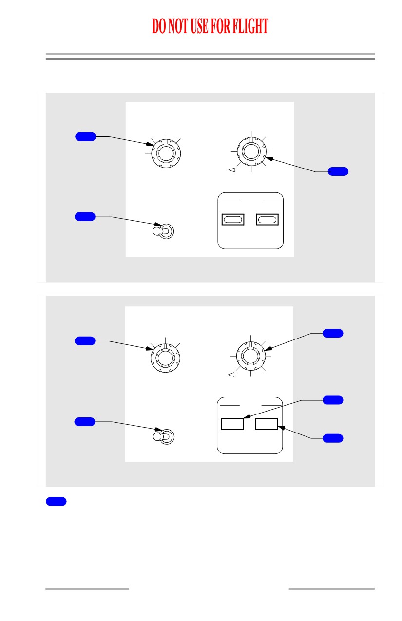
1
N1 SET Knob
[Option - Side by side display]
Refer to section 10, Side by Side - Displays
[Option - Over/Under display]
Refer to section 11, Over/Under - Displays
7.15.3
Engines, APU -
General Controls and Indicators
Boeing 737 Operations Manual
2
FUEL FLOW Switch
[Option - Side by side display]
Refer to section 10, Side by Side - Displays
[Option - Over/Under display]
Refer to section 11, Over/Under - Displays
3
Speed Reference Selector
Refer to Chapter 10, Flight Instruments, Displays.
4
MFD Engine (ENG) Switch
[Option - Over/Under display]
Push - ENG
• displays secondary engine indications on lower DU; or if the lower DU is
unavailable, on upper or inboard DU based on the position of the display
select panel selector
• second push blanks lower DU.
5
MFD System (SYS) Switch
[Option - Over/Under display, flight control surface position indicator, brake
temperature monitor indicator]
Refer to Chapter 13, Hydraulics; Chapter 9, Flight Controls; Chapter 14, Landing
Gear.
Engine Panel
ENGINE
1
2
1
REVERSER
REVERSER
EEC
EEC
ON
ON
ENGINE
ENGINE
2
CONTROL
CONTROL
ALTN
ALTN
3
AFT OVERHEAD PANEL
7.15.4
Engines, APU -
General Controls and Indicators
Boeing 737 Operations Manual
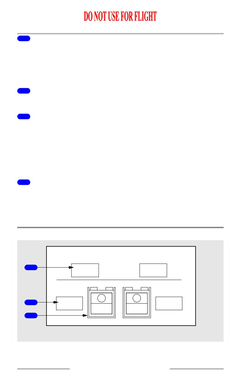
1
REVERSER Lights
Illuminated (amber) - one or more of following has occurred:
• isolation valve or thrust reverser control valve is not in commanded
position
• one or more thrust reverser sleeves are not in commanded state
• auto-restow circuit has been activated
• a failure has been detected in synchronization shaft lock circuitry.
2
ENGINE CONTROL Lights
Illuminated (amber) - engine control system is not dispatchable due to faults in
system.
Light operates when:
• engine is operating and,
• airplane on ground and:
• below 80 kt prior to takeoff or,
• approximately 30 seconds after touchdown.
3
Electronic Engine Control (EEC) Switches
ON - in view (white)
• indicates normal control mode is selected
• engine ratings calculated by EEC from sensed atmospheric conditions and
bleed air demand
• when ON is not in view, the EEC has been manually selected to the
alternate mode.
ALTN - in view (amber)
• indicated EEC has automatically switched to alternate control mode or it
has been selected manually
• EEC provides rated thrust or higher.
Note: Both ON and ALTN may be in view if EEC has automatically switched to
soft alternate mode.
Note: EGT limits must be observed in both normal and alternate control modes.
7.15.5
Engines, APU -
General Controls and Indicators
Boeing 737 Operations Manual
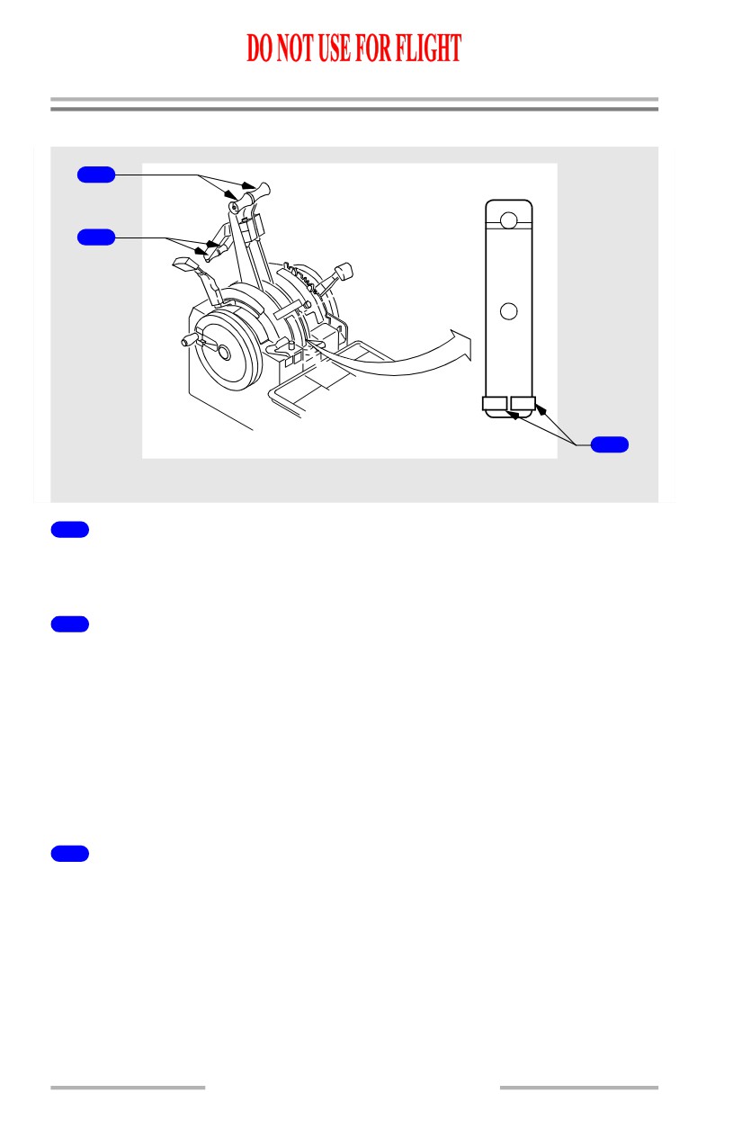
Engine Controls
1
2
IDLE
CUTOFF
1
2
3
CONTROL STAND
1
Forward Thrust Levers -
• controls engine thrust
• cannot be advanced if the reverse thrust lever is in the deployed position.
2
Reverse Thrust Levers -
• controls engine reverse thrust
• cannot select reverse thrust unless related forward thrust lever is at IDLE.
Note: Reverse thrust lever is blocked at reverse idle position until related thrust
reverser is more than 60% deployed.
Note: Movement of reverse thrust lever into reverse thrust engages locking pawl
preventing forward thrust lever from moving. Terminating reverse thrust
removes locking pawl and restores forward thrust lever movement ability.
3
Engine Start Levers
IDLE -
• energizes ignition system through EEC
• electrically opens spar fuel shutoff valve in the wing leading edge
outboard of the pylon
• electrically opens engine-mounted fuel shutoff valve via the EEC.
CUTOFF -
• closes both spar and engine fuel shutoff valves
• de-energizes ignition system.
7.15.6
Engines, APU -
General Controls and Indicators
Boeing 737 Operations Manual
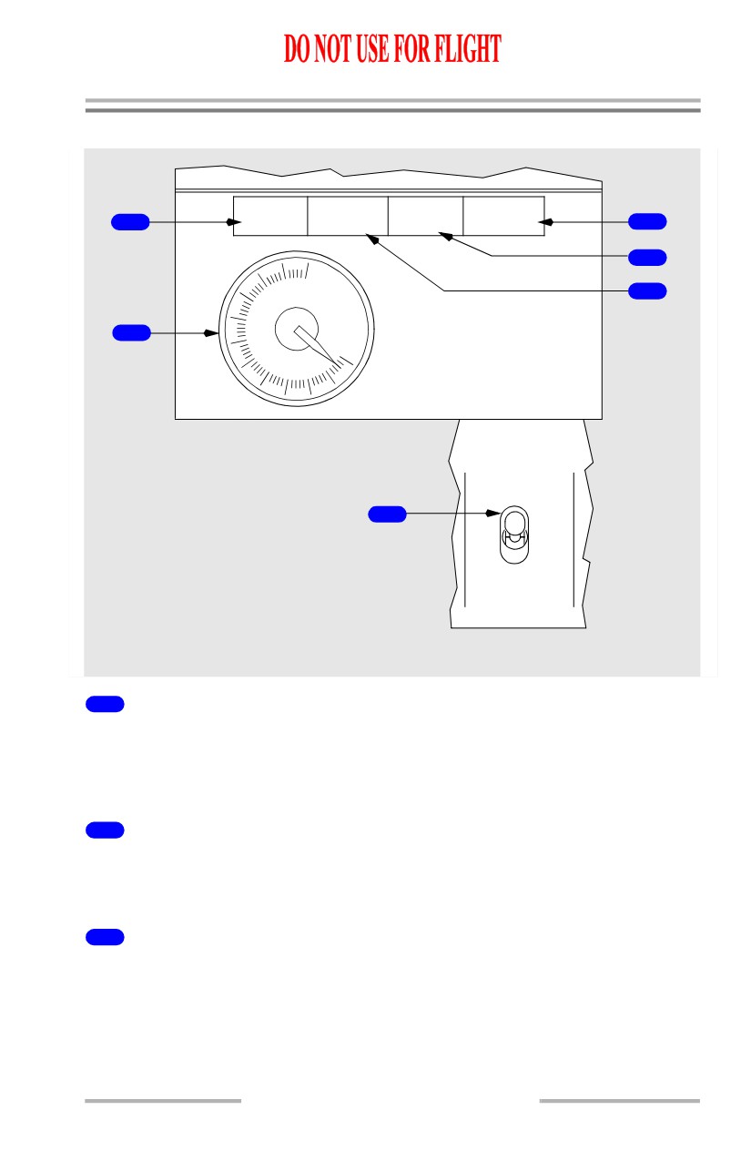
APU
APU
LOW OIL
OVER
MAINT
FAULT
1
PRESSURE
SPEED
3
4
10
EGT
5
8
2
6
0
4
2
APU
OFF
6
ON
START
FORWARD OVERHEAD PANEL
1
APU Maintenance (MAINT) Light
Illuminated (blue) - APU maintenance problem exists:
• APU may be operated
• light is disarmed when APU switch is in OFF.
2
APU Exhaust Gas Temperature (EGT) Indicator
Displays APU EGT
EGT indicator remains powered for 5 minutes after shutdown.
3
APU OVERSPEED Light
Illuminated (amber) -
• APU RPM limit has been exceeded resulting in an automatic shutdown
• overspeed shutdown protection feature has failed a self-test during a
normal APU shutdown
7.15.7