Boeing 737 - 600/700/800/900. Flight Crew Training Manual (1999 year) - page 7
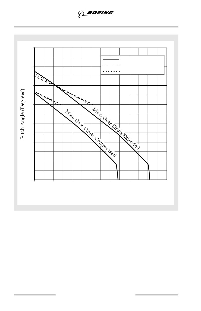
Landing
737-800
14
Aft Body
12
Extended Tail Skid
Aft Drain Mast
10
8
6
4
2
0
0
10
20
30
40
50
60
70
(0)
(25)
(51)
(76)
(102)
(127)
(152)
(178)
Clearance - inches (cm)
6.18
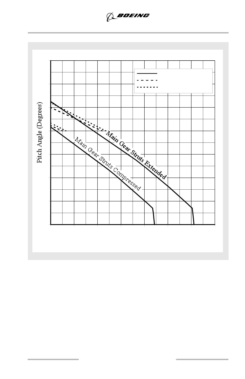
Landing
737-900
14
Aft Body
Extended Tail Skid
12
Aft Drain Mast
10
8
6
4
2
0
0
10
20
30
40
50
60
70
(0)
(25)
(51)
(76)
(102)
(127)
(152)
(178)
Clearance - inches (cm)
6.19
Landing
Pitch and Roll Limit Conditions
The Ground Contact Angles - Normal Landing figure illustrates body roll
angle/pitch angles at which the airplane structure contacts the runway. Prolonged
flare increases the body pitch attitude 2° to 3°. When prolonged flare is coupled
with a misjudged height above the runway aft body contact is possible.
Fly the airplane onto the runway at the desired touchdown point and at the desired
airspeed. Do not hold it off and risk the possibility of a tailstrike.
Note: A smooth touchdown is not the criterion for a safe landing.
6.20
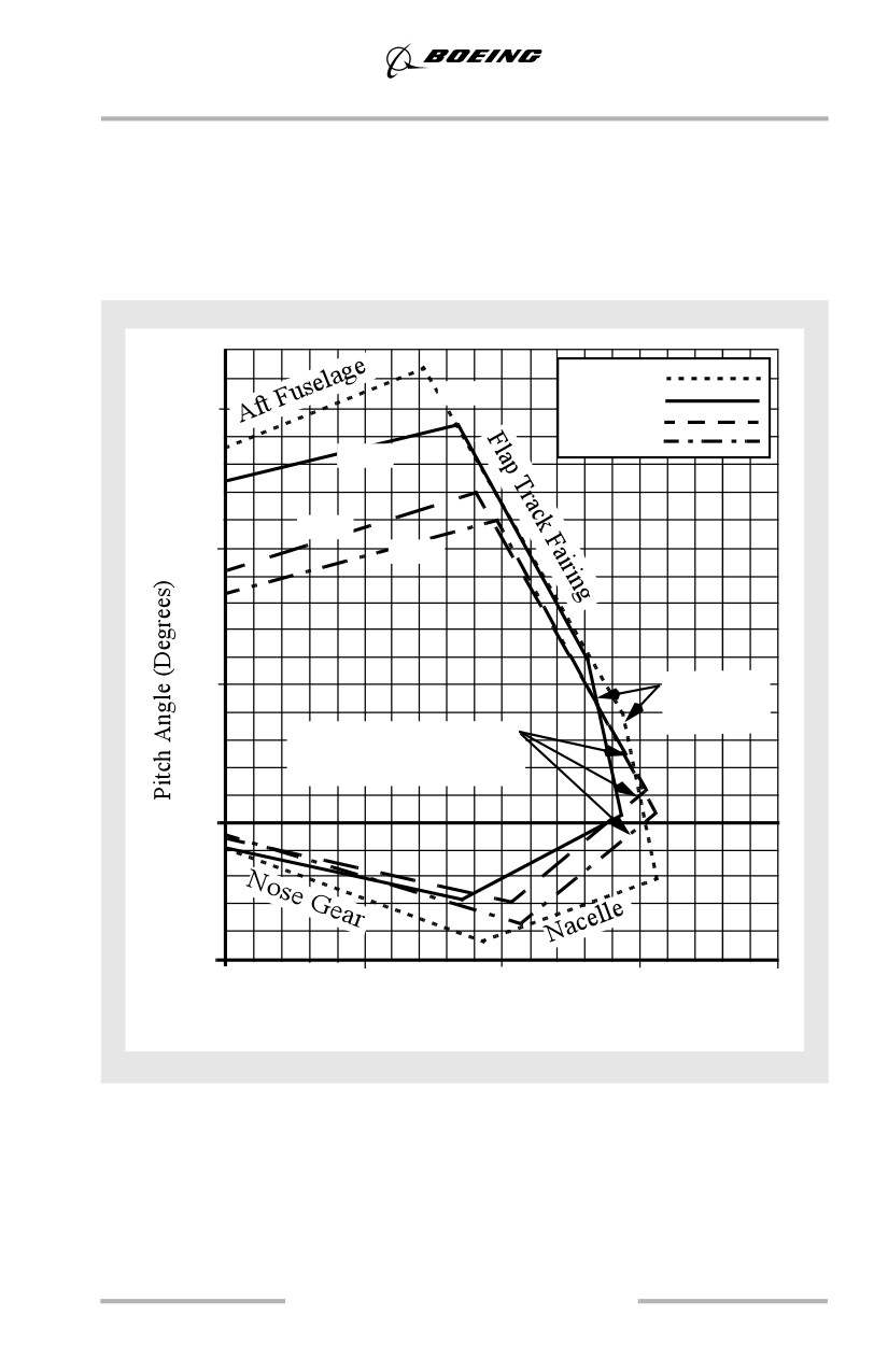
Landing
Ground Contact Angles - Normal Landing
Conditions
• Pitch about main gear centerline
• Stabilizer full nose up
• Slats fully extended
• Elevator full down
• Aileron full down
• Struts compressed
• Roll about outer tire centerline
• Flaps 40
737-600
-600
737-700
15
737-800
737-900
-700
-800
10
-900
5
737-600/700
L E Slat
Extended
Note: 737-800/900 LE slat
and outboard flap track
touch simultaneously.
0
-5
0
5
10
15
20
Roll Angle (Degrees)
6.21
Landing
Landing Roll
Avoid touching down with thrust above idle since this may establish an airplane
nose up pitch tendency and increases landing roll.
After main gear touchdown, initiate the landing roll procedure. If the speedbrakes
do not extend automatically move the speedbrake lever to the UP position without
delay. Fly the nosewheel onto the runway smoothly by relaxing aft control column
pressure. Control column movement forward of neutral should not be required. Do
not attempt to hold the nosewheel off the runway. Holding the nose up after
touchdown for aerodynamic braking is not an effective braking technique.
To avoid possible airplane structural damage, do not make large nose down
control column movements before the nose wheels are lowered to the runway.
To avoid the risk of tailstrike, do not allow the pitch attitude to increase after
touchdown. However, applying excessive nose down elevator during landing can
result in substantial forward fuselage damage. Do not use full down elevator. Use
an appropriate autobrake setting or manually apply wheel brakes smoothly with
steadily increasing pedal pressure as required for runway condition and runway
length available. Maintain deceleration rate with constant or increasing brake
pressure as required until stopped or desired taxi speed is reached.
Speedbrakes
The speedbrake system is controlled with the SPEEDBRAKE lever (which is
moved UP and DOWN). The speedbrake system consists of individual spoiler
panels which the pilot can extend and retract by moving the SPEEDBRAKE lever.
The speedbrakes can be fully raised after touchdown while the nose wheels are
lowered to the runway, with no adverse pitch effects. The speedbrakes spoil the
lift from the wings, which places the airplane weight on the main landing gear,
providing excellent brake effectiveness.
Unless speedbrakes are raised after touchdown, braking effectiveness may be
reduced initially as much as 60%, since very little weight is on the wheels and
brake application may cause rapid anti-skid modulation.
Normally, speedbrakes are armed to extend automatically. Both pilots should
monitor speedbrake extension after touchdown. In the event auto extension fails,
the speedbrake should be manually extended immediately.
Pilot awareness of the position of the speedbrake lever during the landing phase is
important in the prevention of over-run. The position of the speedbrakes should be
announced during the landing phase by the PM. This improves the crew’s
situational awareness of the position of the spoilers during landing and builds
good habit patterns which can prevent failure to observe a malfunctioned or
disarmed spoiler system.
6.22
Landing
Directional Control and Braking during Landing Roll
If the nose wheels are not promptly lowered to the runway, braking and steering
capabilities are significantly degraded and no drag benefit is gained. Rudder
control is effective to approximately 60 knots. Rudder pedal steering is sufficient
for maintaining directional control during the rollout. Do not use the nose wheel
steering wheel until reaching taxi speed. In a crosswind, displace the control wheel
into the wind to maintain wings level which aids directional control. Perform the
landing roll procedure immediately after touchdown. Any delay markedly
increases the stopping distance.
Stopping distance varies with wind conditions and any deviation from
recommended approach speeds.
Factors Affecting Landing Distance
Advisory information for normal and non-normal configuration landing distances
is contained in the PI section of the QRH. Actual stopping distances for a
maximum effort stop are approximately 60% of the dry runway field length
requirement. Factors that affect stopping distance include: height and speed over
the threshold, glide slope angle, landing flare, lowering the nose to the runway, use
of reverse thrust, speedbrakes, wheel brakes and surface conditions of the runway.
Note: Reverse thrust and speedbrake drag are most effective during the high
speed portion of the landing. Deploy the speedbrake lever and activate
reverse thrust with as little time delay as possible.
Note: Speedbrakes fully deployed, in conjunction with maximum reverse thrust
and maximum manual anti-skid braking provides the minimum stopping
distance.
Floating above the runway before touchdown must be avoided because it uses a
large portion of the available runway. The airplane should be landed as near the
normal touchdown point as possible. Deceleration rate on the runway is
approximately three times greater than in the air.
Height of the airplane over the runway threshold also has a significant effect on
total landing distance. For example, on a 3° glide path, passing over the runway
threshold at 100 feet altitude rather than 50 feet could increase the total landing
distance by approximately 950 feet. This is due to the length of runway used up
before the airplane actually touches down.
Glide path angle also affects total landing distance. As the approach path becomes
flatter, even while maintaining proper height over the end of the runway, total
landing distance is increased.
6.23
Landing
Slippery Runway Landing Performance
When landing on slippery runways contaminated with ice, snow, slush or standing
water, the reported braking action must be considered. Advisory information for
reported braking actions of good, medium and poor is contained in the PI section
of the QRH. The performance level associated with good is representative of a wet
runway. The performance level associated with poor is representative of a wet ice
covered runway. Also provided in the QRH are stopping distances for the various
autobrake settings and for non-normal configurations. Pilots should use extreme
caution to ensure adequate runway length is available when poor braking action is
reported.
Pilots should keep in mind slippery/contaminated runway advisory information is
based on an assumption of uniform conditions over the entire runway. This means
a uniform depth for slush/standing water for a contaminated runway or a fixed
braking coefficient for a slippery runway. The data cannot cover all possible
slippery/contaminated runway combinations and does not consider factors such as
rubber deposits or heavily painted surfaces near the end of most runways. With
these caveats in mind, it is up to the airline to determine operating policies based
on the training and operating experience of their flight crews.
One of the commonly used runway descriptors is coefficient of friction. Ground
friction measuring vehicles typically measure this coefficient of friction. Much
work has been done in the aviation industry to correlate the friction reading from
these ground friction measuring vehicles to airplane performance. Use of ground
friction vehicles raises the following concerns:
• the measured coefficient of friction depends on the type of ground friction
measuring vehicle used. There is not a method, accepted worldwide, for
correlating the friction measurements from the different friction
measuring vehicles to each other, or to the airplane's braking capability.
• most testing to date, which compares ground friction vehicle performance
to airplane performance, has been done at relatively low speeds (100
knots or less). The critical part of the airplane's deceleration
characteristics is typically at higher speeds (120 to 150 knots).
6.24
Landing
• ground friction vehicles often provide unreliable readings when
measurements are taken with standing water, slush or snow on the
runway. Ground friction vehicles might not hydroplane (aquaplane) when
taking a measurement while the airplane may hydroplane (aquaplane). In
this case, the ground friction vehicles would provide an optimistic reading
of the runway's friction capability. The other possibility is the ground
friction vehicles might hydroplane (aquaplane) when the airplane would
not, this would provide an overly pessimistic reading of the runway's
friction capability. Accordingly, friction readings from the ground friction
vehicles may not be representative of the airplane's capability in
hydroplaning conditions.
• ground friction vehicles measure the friction of the runway at a specific
time and location. The actual runway coefficient of friction may change
with changing atmospheric conditions such as temperature variations,
precipitation etc. Also, the runway condition changes as more operations
are performed.
The friction readings from ground friction measuring vehicles do supply an
additional piece of information for the pilot to evaluate when considering runway
conditions for landing. Crews should evaluate these readings in conjunction with
the PIREPS (pilot reports) and the physical description of the runway (snow,
slush, ice etc.) when planning the landing. Special care should be taken in
evaluating all the information available when braking action is reported as POOR
or if slush/standing water is present on the runway.
6.25
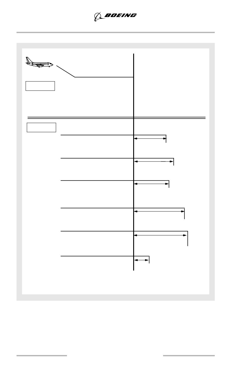
Landing
Factors Affecting Landing Distance (Typical)
•
Maximum effort stop
50'
Flaps 40
•
Stop
Proper
• Normal flare and touchdown
• Verify speedbrake extension
• Apply braking and reverse thrust
simultaneously
• Maintain steady full brake pedal
pressure
Increase in typical landing distance
Improper
Overextended flare
due to improper landing techniques
(3 sec. float after flare)
•
515'-775'
High over threshold
(100' alt.)
•
950'
Speedbrakes not extended
•
420'-825' *
Speedbrakes not extended & thrust
reversers not deployed
•
640'-1165' *
1/2 brake pressure
•
600'-1530' *
High approach speed
(+10 knots)
•
170'-310' *
*Landing distance varies with runway condition, wet or dry.
Data excludes contaminated runway considerations.
6.26
Landing
Wheel Brakes
Braking force is proportional to the force of the tires on the runway and the
coefficient of friction between the tires and the runway. The contact area normally
changes little during the braking cycle. The perpendicular force comes from
airplane weight and any downward aerodynamic force such as speedbrakes.
The coefficient of friction depends on the tire condition and runway surface, (e.g.
concrete, asphalt, dry, wet or icy).
Automatic Brakes
Boeing recommends that whenever runway limited, using higher than normal
approach speeds, landing on slippery runways or landing in a crosswind, the
autobrake system be used.
For normal operation of the autobrake system select a deceleration setting.
Settings include:
• MAX: Used when minimum stopping distance is required. Deceleration
rate is less than that produced by full manual braking
• MED (2 or 3, as installed): Should be used for wet or slippery runways or
when landing rollout distance is limited
• MIN (1, as installed): These settings provide a moderate deceleration
effect suitable for all routine operations.
Flight crew/airline experience with airplane characteristics relative to the various
runway conditions routinely encountered provide initial guidance as to the
desirable level of deceleration selected.
Immediate initiation of reverse thrust at main gear touchdown and full reverse
thrust allow the autobrake system to reduce brake pressure to the minimum level.
Since the autobrake system senses deceleration and modulates brake pressure
accordingly, the proper application of reverse thrust results in reduced braking for
a large portion of the landing roll.
The importance of establishing the desired reverse thrust level as soon as possible
after touchdown cannot be overemphasized. This minimizes brake temperatures
and tire and brake wear and reduces stopping distance on very slippery runways.
The use of minimum reverse thrust almost doubles the brake energy requirements
and can result in brake temperatures much higher than normal.
After touchdown, crewmembers should be alert for autobrake disengagement
annunciations. The PM should notify the PF anytime the autobrakes disengage.
If stopping distance is not assured with autobrakes engaged, the PF should
immediately apply manual braking sufficient to assure deceleration to a safe taxi
speed within the remaining runway.
6.27
Landing
A table in the PI section of the QRH shows the relative stopping capabilities of the
available autobrake selections.
Transition to Manual Braking
The speed at which the transition from autobrakes to manual braking is made
depends upon airplane deceleration rate, runway conditions and stopping
requirements. When transitioning to manual braking, keep the speedbrakes
deployed and use reverse thrust as required until taxi speed. This is especially
important when nearing the end of the runway where rubber deposits affect
stopping ability.
When transitioning from the autobrake system to manual braking, the PF should
notify the PM. Techniques for release of autobrakes can affect passenger comfort
and stopping distance. These techniques are:
• stow the speed brake handle. When stopping distance within the
remaining runway is assured, this method provides a smooth transition to
manual braking, is effective before or after thrust reversers are stowed,
and is less dependent on manual braking technique
• smoothly apply brake pedal force as in a normal stop, until the autobrake
system disarms. Following disarming of the autobrakes, smoothly release
brake pedal pressure. Disarming the autobrakes before coming out of
reverse thrust provides a smooth transition to manual braking
• manually position the autobrake selector off (normally done by the PM at
the direction of the PF).
Manual Braking
The following technique for manual braking provides optimum braking for all
runway conditions:
The pilot’s seat and rudder pedals should be adjusted so that it is possible to apply
maximum braking with full rudder deflection.
Immediately after main gear touchdown, smoothly apply a constant brake pedal
pressure for the desired braking. For short or slippery runways, use full brake
pedal pressure.
• do not attempt to modulate, pump or improve the braking by any other
special techniques
• do not release the brake pedal pressure until the airplane speed has been
reduced to a safe taxi speed
• the antiskid system stops the airplane for all runway conditions in a
shorter distance than is possible with either antiskid off or brake pedal
modulation.
6.28
Landing
The antiskid system adapts pilot applied brake pressure to runway conditions by
sensing an impending skid condition and adjusting the brake pressure to each
individual wheel for maximum braking effort. When brakes are applied on a
slippery runway, several skid cycles occur before the antiskid system establishes
the right amount of brake pressure for the most effective braking.
If the pilot modulates the brake pedals, the antiskid system is forced to readjust the
brake pressure to establish optimum braking. During this readjustment time,
braking efficiency is lost.
Low available braking coefficient of friction on extremely slippery runways at
high speeds may be interpreted as a total antiskid failure. Pumping the brakes or
turning off the antiskid degrades braking effectiveness. Maintain steadily
increasing brake pressure, allowing the antiskid system to function at its optimum.
Although immediate braking is desired, manual braking techniques normally
involve a four to five second delay between main gear touchdown and brake pedal
application even when actual conditions reflect the need for a more rapid initiation
of braking. This delayed braking can result in the loss of 800 to 1,000 feet of
runway. Directional control requirements for crosswind conditions and low
visibility may further increase the delays. Distractions arising from a
malfunctioning reverser system can also result in delayed manual braking
application.
Braking with Antiskid Inoperative
When the antiskid system is inoperative, the following techniques apply:
• ensure that the nose wheels are on the ground and the speedbrakes are
extended before applying the brakes
• initiate wheel braking using very light pedal pressure and increase
pressure as ground speed decreases
• apply steady pressure and DO NOT PUMP the pedals.
Flight testing has demonstrated that braking effectiveness on a wet grooved
runway is similar to that of a dry runway. Caution however must be exercised
when braking on any wet, ungrooved portions of the runway with antiskid
inoperative to avoid blown tires.
Brake Cooling
A series of taxi-back or stop and go landings without additional in-flight brake
cooling can cause excessive brake temperatures. The energy absorbed by the
brakes from each landing is cumulative.
Extending the gear a few minutes early in the approach normally provides
sufficient cooling for a landing. Total in-flight cooling time can be determined
from the Performance Inflight section of the QRH.
6.29
Landing
The optional brake temperature monitoring system may be used for additional
flight crew guidance in assessing brake energy absorption. This system indicates
a stabilized value approximately fifteen minutes after brake energy absorption.
Therefore, an immediate or reliable indication of tire or hydraulic fluid fire, wheel
bearing problems, or wheel fracture is not available. The brake temperature
monitor readings may vary between brakes during normal braking operations.
Note: Brake energy data provided in the QRH should be used to identify potential
overheat situations.
To minimize brake temperature build-up:
• for airplanes without operative brake temperature monitoring systems:
If the last ground time plus present flight time is less than 90 minutes,
extend the landing gear 5 minutes early or 7 minutes prior to landing
• for airplanes with operating brake temperature monitoring systems:
Extend the landing gear approximately one minute early for each unit of
brake temperature above normal.
Close adherence to recommended landing roll procedures ensures minimum brake
temperature build up.
Reverse Thrust Operation
Awareness of the position of the forward and reverse thrust levers must be
maintained during the landing phase. Improper seat position as well as long
sleeved apparel may cause inadvertent advancement of the forward thrust levers,
preventing movement of the reverse thrust levers.
The position of the hand should be comfortable, permit easy access to the
autothrottle disconnect switch, and allow control of all thrust levers, forward and
reverse, through full range of motion.
Note: Reverse thrust always reduces the “brake only” stopping distance, brake
and tire wear. Reverse thrust is most effective at high speeds.
After touchdown, with the thrust levers at idle, rapidly raise the reverse thrust
levers up and aft to the interlock position, then to the number 2 reverse thrust
detent. Conditions permitting, limit reverse thrust to the number 2 detent. The PM
should monitor engine operating limits and call out any engine operational limits
being approached or exceeded, any thrust reverser failure, or any other
abnormalities.
6.30
Landing
Maintain reverse thrust as required, up to maximum, until the airspeed approaches
60 knots. At this point start reducing the reverse thrust so that the reverse thrust
levers are moving down at a rate commensurate with the deceleration rate of the
airplane. The thrust levers should be positioned to reverse idle by taxi speed, then
to full down after the engines have decelerated to idle. The PM should call out 60
knots to assist the PF in scheduling the reverse thrust. The PM should also call out
any inadvertent selection of forward thrust as reverse thrust is cancelled. If an
engine surges during reverse thrust operation, quickly select reverse idle on all
engines.
6.31
Landing
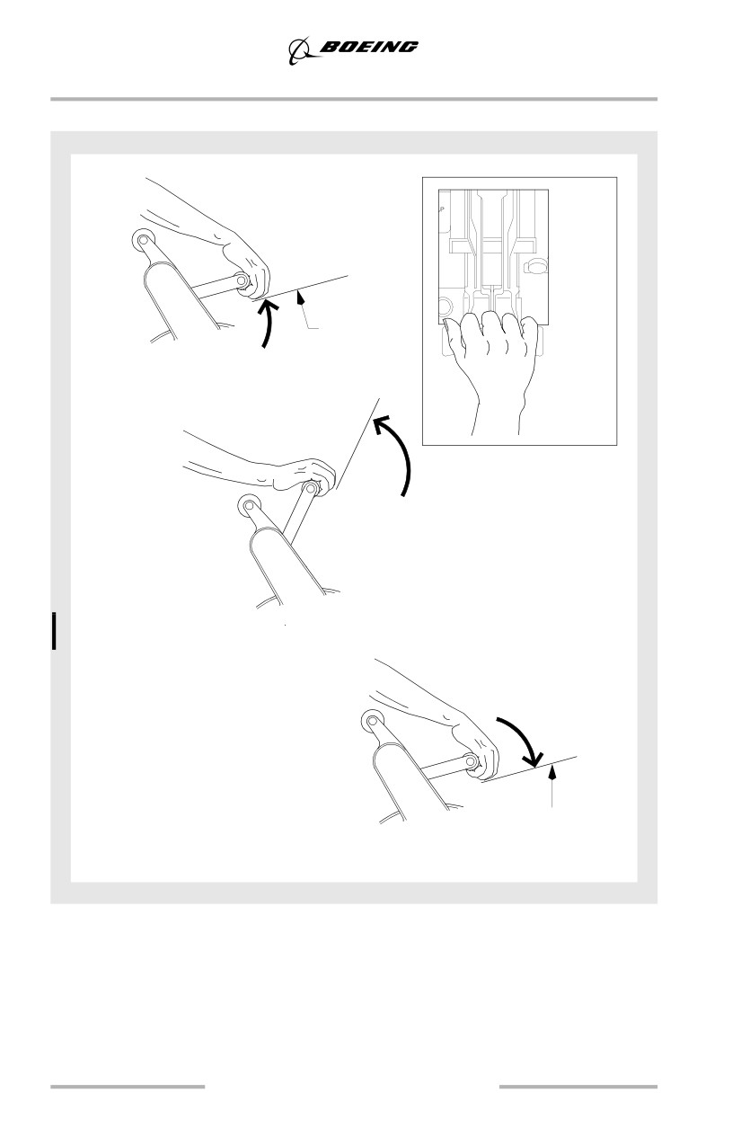
Reverse Thrust Operations
Reverser
Interlock
At Touchdown:
Up and aft rapidly to interlock.
Maintain light pressure on interlock.
Gripping
Pattern
After reverser interlock release:
Apply reverse thrust as needed until 60 knots.
Idle reverse detent
At 60 knots:
Decrease to idle reverse by taxi speed.
6.32
Landing
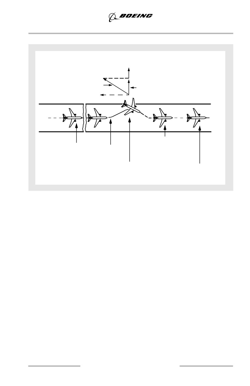
Reverse Thrust and Crosswind (All Engines)
Crosswind
Component
Reverse Thrust
Reverse Thrust Vector
Side Force
Runway Component
Component
• Straighten
• Touchdown
• Roll Path
Crosswind
• Speedbrake up,
• Reapply Braking
brakes on
• Initiate Reverse
• Brakes Off
• Apply
• Reverse Idle
symmetrical
reverse thrust
This figure shows a directional control problem during a landing rollout on a
slippery runway with a crosswind. As the airplane starts to weathervane into the
wind, the reverse thrust side force component adds to the crosswind component
and drifts the airplane to the downwind side of the runway. Main gear tire
cornering forces available to counteract this drift are at a minimum when the
antiskid system is operating at maximum braking effectiveness for the existing
conditions.
To correct back to the centerline, reduce reverse thrust to reverse idle and release
the brakes. This minimizes the reverse thrust side force component without the
requirement to go through a full reverser actuation cycle, and improve tire
cornering forces for realignment with the runway centerline. Use rudder pedal
steering and differential braking as required, to prevent over correcting past the
runway centerline. When re-established near the runway centerline, apply
maximum braking and symmetrical reverse thrust to stop the airplane.
Reverse Thrust - EEC in the Alternate Mode
Use normal reverse thrust techniques.
6.33
Landing
Reverse Thrust - Engine Inoperative
Asymmetrical reverse thrust may be used with one engine inoperative. Use normal
reverse thrust procedures and techniques with the operating engine. If directional
control becomes a problem during deceleration, return the thrust lever to the
reverse idle detent.
Crosswind Landings
The crosswind guidelines shown below were derived through flight test data,
engineering analysis and flight simulator evaluations. These crosswind guidelines
are based on steady wind (no gust) conditions and include all engines operating
and engine inoperative. Gust effects were evaluated and tend to increase pilot
workload without significantly affecting the recommended guidelines.
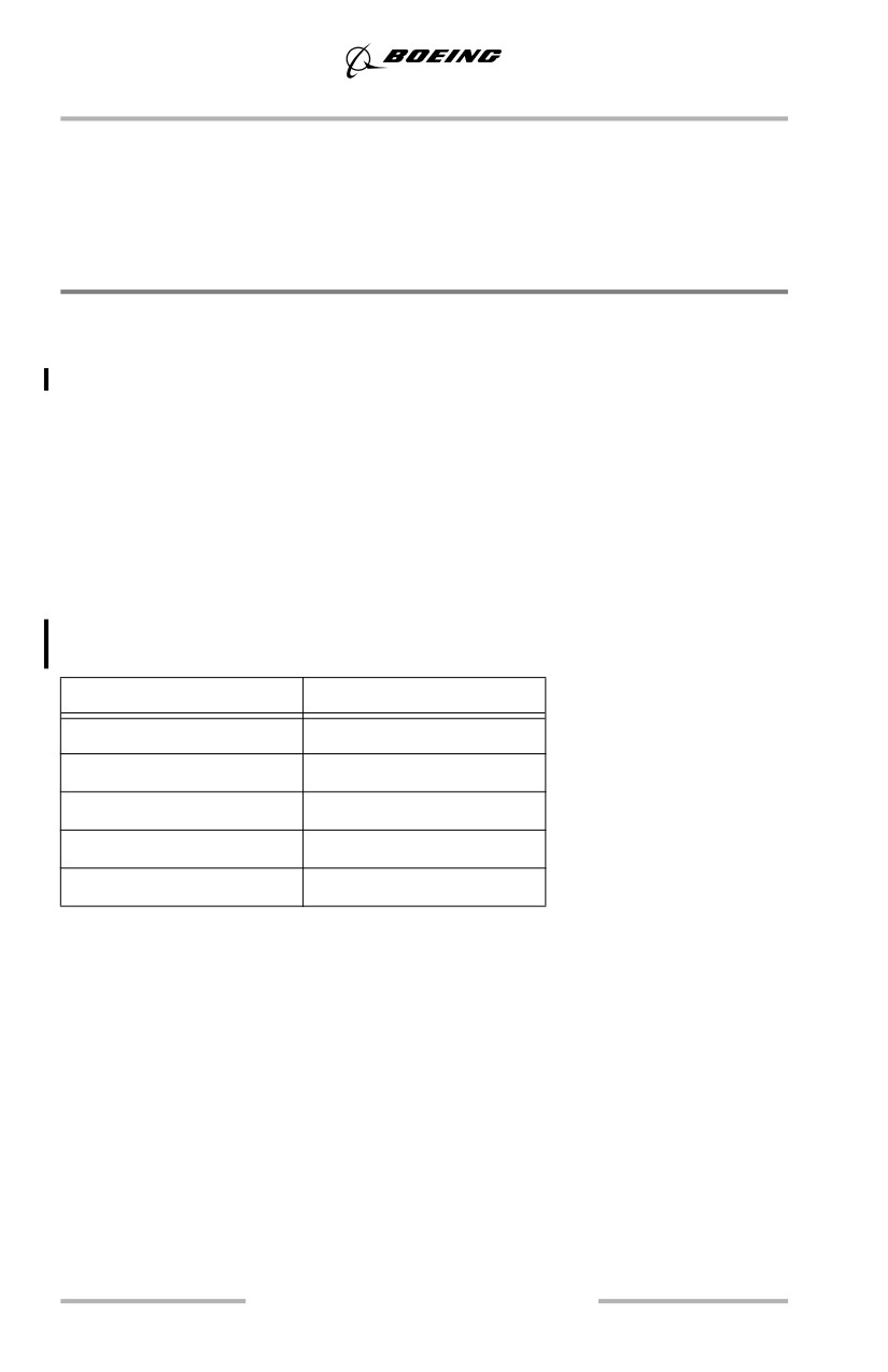
Landing Crosswind Guidelines
Crosswind guidelines are not considered limitations. Crosswind guidelines are
provided to assist operators in establishing their own crosswind policies.
On slippery runways, crosswind guidelines are a function of runway surface
condition. These guidelines assume adverse airplane loading and proper pilot
technique.
Runway Condition
Crosswind - Knots *
Dry
40 ***
Wet
40 ***
Standing Water/Slush
20
Snow - No Melting **
35 ***
Ice - No Melting **
17
Note: Reduce crosswind guidelines by 5 knots on wet or contaminated runways
whenever asymmetric reverse thrust is used.
*Winds measured at 33 feet (10 m) tower height and apply for runways 148 feet
(45m) or greater in width.
** Landing on untreated ice or snow should only be attempted when no melting
is present.
*** Sideslip only (zero crab) landings are not recommended with crosswinds in
excess of 17 knots at flaps 15, 20 knots at flaps 30, or 23 knots at flaps 40. This
recommendation ensures adequate ground clearance and is based on maintaining
adequate control margin.
Note: Reduce sideslip only (zero crab) landing crosswinds by 2 knots for
airplanes with winglets.
6.34
Landing
Crosswind Landing Techniques
Three methods of performing crosswind landings are presented. They are the
touchdown in a crab, the de-crab technique (with removal of crab in flare), and the
sideslip technique. Whenever a crab is maintained during a crosswind approach,
offset the flight deck on the upwind side of centerline so that the main gear touches
down in the center of the runway.
De-Crab During Flare
The objective of this technique is to maintain wings level throughout the
approach, flare, and touchdown. On final approach, a crab angle is established
with wings level to maintain the desired track. Just prior to touchdown while
flaring the airplane, downwind rudder is applied to eliminate the crab and align
the airplane with the runway centerline.
As rudder is applied, the upwind wing sweeps forward developing roll. Hold
wings level with simultaneous application of aileron control into the wind. The
touchdown is made with cross controls and both gear touching down
simultaneously. Throughout the touchdown phase upwind aileron application is
utilized to keep the wings level.
Touchdown In Crab
The airplane can land using crab only (zero side slip) up to the landing crosswind
guideline speeds. (See the landing crosswind guidelines table, this chapter).
On dry runways, upon touchdown the airplane tracks toward the upwind edge of
the runway while de-crabbing to align with the runway. Immediate upwind aileron
is needed to ensure the wings remain level while rudder is needed to track the
runway centerline. The greater the amount of crab at touchdown, the larger the
lateral deviation from the point of touchdown. For this reason, touchdown in a
crab only condition is not recommended when landing on a dry runway in strong
crosswinds.
On very slippery runways, landing the airplane using crab only reduces drift
toward the downwind side at touchdown, permits rapid operation of spoilers and
autobrakes because all main gears touchdown simultaneously, and may reduce
pilot workload since the airplane does not have to be de-crabbed before
touchdown. However, proper rudder and upwind aileron must be applied after
touchdown to ensure directional control is maintained.
Sideslip (Wing Low)
The sideslip crosswind technique aligns the airplane with the extended runway
centerline so that main gear touchdown occurs on the runway centerline.
6.35
Landing
The initial phase of the approach to landing is flown using the crab method to
correct for drift. Prior to the flare the airplane centerline is aligned on or parallel
to the runway centerline. Downwind rudder is used to align the longitudinal axis
to the desired track as aileron is used to lower the wing into the wind to prevent
drift. A steady sideslip is established with opposite rudder and low wing into the
wind to hold the desired course.
Touchdown is accomplished with the upwind wheels touching just before the
downwind wheels. Overcontrolling the roll axis must be avoided because
overbanking could cause the engine nacelle or outboard wing flap to contact the
runway. (See Ground Clearance Angles - Normal Landing charts, this chapter.)
Properly coordinated, this maneuver results in nearly fixed rudder and aileron
control positions during the final phase of the approach, touchdown, and
beginning of the landing roll. However, since turbulence is often associated with
crosswinds, it is often difficult to maintain the cross control coordination through
the final phase of the approach to touchdown.
If the crew elects to fly the sideslip to touchdown, it may be necessary to add a
crab during strong crosswinds. (See the landing crosswind guidelines table, this
chapter). Main gear touchdown is made with the upwind wing low and crab angle
applied. As the upwind gear touches first, a slight increase in downwind rudder is
applied to align the airplane with the runway centerline. At touchdown, increased
application of upwind aileron should be applied to maintain wings level.
Overweight Landing
Overweight landings may be safely accomplished by using normal landing
procedures and techniques. There are no adverse handling characteristics
associated with overweight landings. Landing distance is normally less than
takeoff distance for flaps 30 or 40 landings at all gross weights. However, wet or
slippery runway field length requirements should be verified from the landing
distance charts in the PI chapter of the QRH. Brake energy limits will not be
exceeded for flaps 30 or 40 landings at all gross weights.
Note: Use of flaps 30 rather than flaps 40 is recommended to provide increased
margin to flap placard speed.
If stopping distance is a concern, reduce the landing weight as much as possible.
At the captain’s discretion, reduce weight by holding at low altitude with a high
drag configuration (gear down) to achieve maximum fuel burn-off.
Analysis has determined that, when landing at high gross weights at speeds
associated with non-normal procedures requiring flaps set at 15 or less, maximum
effort stops may exceed the brake energy limits. The gross weights where this
condition can occur are well above maximum landing weights. For these
non-normal landings, maximize use of the available runway for stopping.
6.36
Landing
Observe flap placard speeds during flap extension and on final approach. In the
holding and approach patterns, maneuvers should be flown at the normal
maneuver speeds. During flap extension, airspeed can be reduced by as much as
20 knots below normal maneuver speeds before extending to the next flap
position. These lower speeds result in larger margins to the flap placards, while
still providing normal bank angle maneuvering capability, but do not allow for a
15° overshoot margin in all cases.
Use the longest available runway, and consider wind and slope effects. Where
possible avoid landing in tailwinds, on runways with negative slope, or on
runways with less than normal braking conditions. Do not carry excess airspeed
on final. This is especially important when landing during an engine inoperative
or other non-normal condition. At weights above the maximum landing weight,
the final approach maximum wind correction may be limited by the flap placards
and load relief system.
Fly a normal profile. Ensure that a higher than normal rate of descent does not
develop. Do not hold the airplane off waiting for a smooth landing. Fly the
airplane onto the runway at the normal touchdown point. If a long landing is likely
to occur, go-around. After touchdown, immediately apply maximum reverse
thrust using all of the available runway for stopping to minimize brake
temperatures. Do not attempt to make an early runway turnoff.
Autobrake stopping distance guidance is contained in the Performance Inflight
section of the QRH. If adequate stopping distance is available based upon
approach speed, runway conditions, and runway length, the recommended
autobrake setting should be used.
Overweight Autolands Policy
Boeing does not recommend overweight autolands. Autopilots on Boeing
airplanes are not certified for automatic landings above maximum landing weight.
At higher than normal speeds and weights, the performance of these systems may
not be satisfactory and has not been thoroughly tested. An automatic approach
may be attempted, however the pilot should disengage the autopilot prior to flare
height and accomplish a manual landing.
6.37
Landing
In an emergency, should the pilot determine that an overweight autoland is the
safest course of action, the approach and landing should be closely monitored by
the pilot and the following factors considered:
• touchdown may be beyond the normal touchdown zone; allow for
additional landing distance.
• touchdown at higher than normal sink rates may result in exceeding
structural limits.
• plan for a go-around or manual landing if autoland performance is
unsatisfactory; automatic go-arounds can be initiated until just prior to
touchdown, and can be continued even if the airplane touches down after
initiation of the go-around.
6.38
Maneuvers
Chapter 7
Table of Contents
Section TOC
7.TOC Maneuvers-Table of Contents
Preface
7.1
Acceleration to and Deceleration from VMO
7.1
Engine Out Familiarization
7.2
Rudder and Lateral Control
7.2
Thrust and Airspeed
7.3
High Altitude Maneuvering, “G” Buffet
7.4
Rapid Descent
7.5
Autopilot Entry and Level Off
7.6
Manual Entry and Level Off
7.7
Landing Gear Extended Descent
7.7
After Level Off
7.7
Stall Recovery
7.8
Approach to Stall Recovery
7.8
Stick Shaker and Stall Speeds
7.11
Recovery from a Fully Developed Stall
7.20
Steep Turns
7.21
Entry
7.21
During Turn
7.21
Attitude Indicator
7.21
Vertical Speed Indicator
7.21
Altimeter
7.21
Airspeed
7.22
Rollout
7.22
7.TOC.1
Maneuvers -
Table of Contents
Terrain Avoidance
7.22
Traffic Alert and Collision Avoidance System (TCAS)
7.22
Use of TA/RA, TA Only, and Transponder Only Modes
7.22
Traffic Advisory (TA)
7.23
Resolution Advisory (RA)
7.23
Upset Recovery
7.24
General
7.24
Upset Recovery Techniques
7.28
Windshear
7.28
General
7.28
Airplane Performance in Windshear
7.28
Avoidance, Precautions and Recovery
7.29
7.TOC.2
Maneuvers
Chapter 7
Preface
This chapter outlines the recommended operating practices and techniques used
during maneuvers in both the training and operational environment. The flight
profile illustrations represent the Boeing recommended basic configuration during
the accomplishment of the flight maneuvers, and provides a basis for
standardization and crew coordination.
Maneuvering for events such as Approach to Stall Recovery, Terrain Avoidance,
Traffic Avoidance, Upset Recovery, or Windshear may result in deviation from the
ATC clearance. The crew should expeditiously return to the applicable ATC
clearance immediately following such maneuvering unless otherwise directed.
Acceleration to and Deceleration from VMO
Acceleration to and deceleration from VMO demonstrates performance
capabilities and response to speed, thrust, and configuration changes throughout
the medium altitude speed range of the airplane. This maneuver is performed in
the full flight simulator and is for demonstration purposes only. It is normally
performed at 10,000 to 15,000 feet, simulating slowdown to 250 knots due to
speed restrictions.
VMO is a structural limitation and is the maximum operating indicated airspeed.
It is a constant airspeed from sea level to the altitude where VMO and MMO
coincide. MMO is the structural limitation above this altitude. Sufficient thrust is
available to exceed VMO in level flight at lower altitudes. Failure to reduce to
cruise thrust in level flight can result in excessive airspeed.
Begin the maneuver at existing cruise speed with the autothrottle connected and
the autopilot disconnected. Set command speed to VMO. As speed increases
observe:
• nose down trim required to keep airplane in trim and maintain level flight
• handling qualities during acceleration
• autothrottle protection at VMO.
At a stabilized speed just below VMO execute turns at high speed while
maintaining altitude. Next, accelerate above VMO by disconnecting the
autothrottle and increasing thrust.
When the overspeed warning occurs reduce thrust levers to idle, set command
speed to 250 knots, and decelerate to command speed. Since the airplane is
aerodynamically clean, any residual thrust results in a longer deceleration time. As
airspeed decreases observe that nose up trim is required to keep airplane in trim
and maintain level flight. During deceleration note the distance traveled from the
time the overspeed warning stops until reaching 250 knots.
7.1
Maneuvers
Once stabilized at 250 knots, set command speed to flaps up maneuvering speed
and decelerate to command speed, again noting the distance traveled during
deceleration. Observe the handling qualities of the airplane during deceleration.
This maneuver may be repeated using speedbrakes to compare deceleration times
and distances.
Engine Out Familiarization
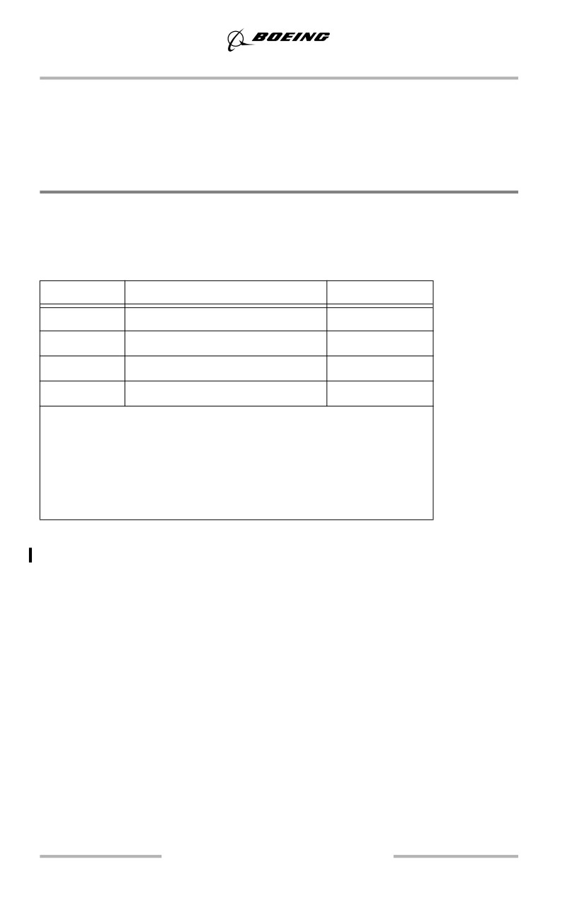
The exercises shown in the following table are performed to develop proficiency
in handling the airplane with one engine inoperative and gain familiarization with
rudder control requirements.
Condition One
Condition Two
Airspeed
Flaps up maneuvering speed
V2
Landing Gear
Up
Down
Flaps
Up
15
Thrust
As Required
MCT
When In Trim - Retard one thrust lever to idle
Controls - Apply to maintain heading, wings level
Rudder - Apply to center control wheel
Airspeed - Maintain with thrust (Condition One) Pitch (Condition Two)
Trim - As required to relieve control forces
One engine out controllability is excellent during takeoff roll and after lift-off.
Minimum control speed in the air is below VR and VREF.
Rudder and Lateral Control
This familiarization is performed to develop proficiency in handling the airplane
with an engine inoperative. It also helps to gain insight into rudder control
requirements.
Under instrument conditions the instrument scan is centered around the attitude
indicator. Roll is usually the first indication of an asymmetric condition. Roll
control (ailerons) should be used to hold the wings level or maintain the desired
bank angle. Stop the yaw by smoothly applying rudder at the same rate that thrust
changes. When the rudder input is correct, very little control wheel displacement
is necessary. Refine the rudder input as required and trim the rudder so the control
wheel remains approximately level.
7.2
Maneuvers
When the rudder is trimmed to level the control wheel, the airplane maintains
heading. A small amount of bank toward the operating engine may be noticeable
on the bank indicator. The slip/skid indicator is displaced slightly toward the
operating engine.
If the airplane is trimmed with too much control wheel displacement, full lateral
control is not available and spoilers on one wing may be raised, increasing drag.
Make turns at a constant airspeed and hold the rudder displacement constant. Do
not attempt to coordinate rudder and lateral control in turns. Rudder pedal inputs
produce roll due to yaw and induce the pilot to counter rudder oscillations with
opposite control wheel.
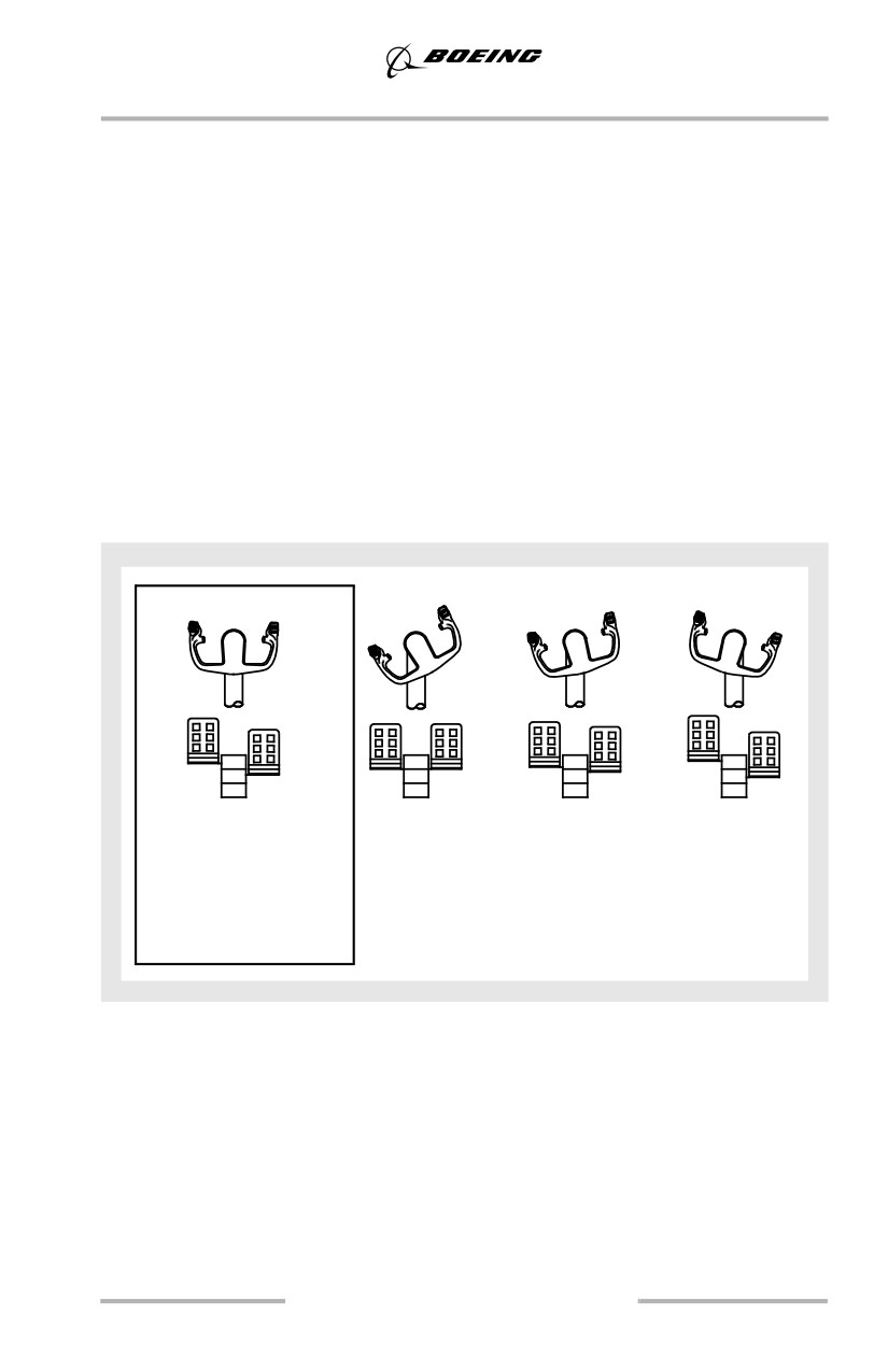
The following figure shows correct and incorrect use of the rudder.
If an engine failure occurs with the autopilot engaged, manually position the
rudder to approximately center the control wheel and add thrust. Trim the rudder
to relieve rudder pedal pressure.
Correct
Incorrect
Incorrect
Incorrect
(Recommended)
Wheel only
Not enough
Too much
Control wheel
No rudder
rudder
rudder
approximately level,
skid/slip slightly out,
rudder as required
Condition: Engine out right wing.
Thrust and Airspeed
If not thrust limited, apply additional thrust, if required, to control the airspeed.
The total two engine fuel flow existing at the time of engine failure may be used
initially to establish a thrust setting at low altitude. If performance limited (high
altitude), adjust airplane attitude to maintain airspeed while setting maximum
continuous thrust.
Note: Autothrottle should not be used with an engine inoperative.
7.3
Maneuvers
High Altitude Maneuvering, “G” Buffet
Airplane buffet reached as a result of airplane maneuvering is commonly referred
to as “g” buffet. During turbulent flight conditions, it is possible to experience
high altitude “g” buffet at speeds less than MMO. In training, buffet is induced to
demonstrate the airplane's response to control inputs during flight in buffet.
Establish an airspeed of 0.80M. Induce “g” buffet by smoothly increasing the bank
angle until the buffet is noticeable. Increase the rate of descent while increasing
the bank angle to maintain airspeed. Do not exceed 45° of bank. If buffet does not
occur by 45° of bank, increase control column back pressure until buffet occurs.
When buffet is felt, relax back pressure and smoothly roll out to straight and level.
Notice that the controls are fully effective at all times.
7.4
Maneuvers
Rapid Descent
This section addresses basic techniques and procedures for a rapid descent. Some
routes over mountainous terrain require careful operator planning to include
carrying additional oxygen, special procedures, higher initial level off altitudes,
and emergency routes in the event a depressurization is experienced. These
requirements are normally addressed in an approved company route manual or
other document that addresses route specific depressurization procedures.
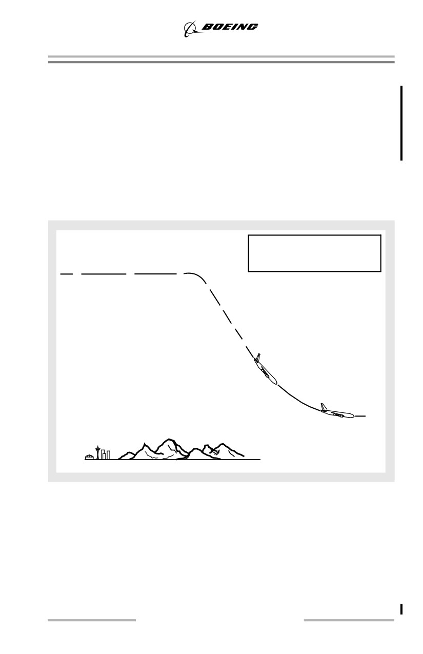
This maneuver is designed to bring the airplane down smoothly to a safe altitude,
in the minimum time, with the least possible passenger discomfort.
Note: Use of the autopilot is recommended.
Select lower
Close thrust
If structural integrity is in
Announce
altitude on MCP
lever and extend
doubt, limit airspeed and avoid
descent
Select LVL CHG
speedbrakes
high maneuvering loads.
•
•
•
Descend straight ahead or
•
initiate turn with HDG SEL
Level off at lowest safe
Adjust speed and
•
altitude or 10,000 feet,
level off altitude
whichever is higher
Target speed MMO/VMO
•
Notify ATC and request
•
Speedbrakes in
altimeter setting
down detent
Call out altitudes
LRC speed
or 300 knots
•
Determine new course of action
If the descent is performed because of a rapid loss of cabin pressure, crewmembers
should place oxygen masks on and establish communication at the first indication
of a loss of cabin pressurization. Verify cabin pressure is uncontrollable, and if so
begin descent. If structural damage exists or is suspected, limit airspeed to current
speed or less. Avoid high maneuvering loads.
Perform the procedure deliberately and methodically. Do not be distracted from
flying the airplane. If icing conditions are entered, use anti-ice and thrust as
required.
Note: Rapid descents are normally made with the landing gear up.
7.5
Maneuvers
The PM checks the lowest safe altitude, notifies ATC, and obtains an altimeter
setting (QNH). Both pilots should verify that all recall items have been
accomplished and call out any items not completed. The PM calls out 2,000 feet
and 1,000 feet above the level off altitude.
Level off at the lowest safe altitude or 10,000 feet, whichever is higher. Lowest
safe altitude is the Minimum Enroute Altitude (MEA), Minimum Off Route
Altitude (MORA), or any other altitude based on terrain clearance, navigation aid
reception, or other appropriate criteria.
If severe turbulent air is encountered or expected, reduce to the turbulent air
penetration speed.
Autopilot Entry and Level Off
Level Change (LVL CHG)
Because of airspeed and altitude protection and reduced crew workload, use of the
autopilot with LVL CHG mode is the recommended technique for rapid descents.
Use of the V/S mode is not recommended.
First set a lower altitude in the altitude window. Select LVL CHG, close the thrust
levers and smoothly extend the speedbrakes. Fly straight ahead or initiate a turn
using HDG SEL. Autothrottles should be left engaged. The airplane pitches down
smoothly while the thrust levers retard to idle. Adjust the speed as needed and
ensure the altitude window is correctly set for the level off. During descent, the
IAS/MACH speed window changes from MACH to IAS at approximately 300
KIAS. Manually reset to VMO as needed.
When approaching the target altitude, ensure the altitude is set in the MCP altitude
select window. Altitude capture engages automatically. Adjusting the command
speed to approximately LRC or 300 knots before level-off aids in smoothly
transitioning to level flight. The pitch mode then controls altitude and the thrust
levers increase to hold speed. Smoothly return the speedbrake lever to the down
detent during the level off maneuver.
When descending with the autopilot engaged and the speedbrakes extended at
speeds near VMO/MMO, the airspeed may momentarily increase to above
VMO/MMO if the speedbrakes are retracted quickly. To avoid this condition,
smoothly and slowly retract the speedbrakes to allow the autopilot sufficient time
to adjust the pitch attitude to maintain the airspeed within limits.
When the speedbrakes are retracted during altitude capture near VMO/MMO, a
momentary overspeed condition may also occur. This is because the autopilot
captures the selected altitude smoothly by maintaining a fixed path while the
thrust is at or near idle. To avoid this condition, it may be necessary to reduce the
selected speed and/or descent rate before altitude capture or reduce the selected
speed and delay speedbrake retraction until after level off is complete.
7.6
Maneuvers
Control Wheel Steering (CWS)
CWS may be used to reduce pilot workload. Follow the manually flown procedure
but instead of disengaging the autopilot, engage CWS.
Manual Entry and Level Off
The entry may be accomplished on heading or a turn may be made to clear the
airway or controlled track. However, since extending the speedbrakes initially
reduces the maneuver margin, it is recommended that turns not be initiated until
the airplane is established in the descent.
To manually fly the maneuver, disconnect the autothrottles and retard thrust levers
to idle. Smoothly extend the speedbrakes, disconnect the autopilot and smoothly
lower the nose to initial descent attitude (approximately 10 degrees nose down).
About 10 knots before reaching target speed, slowly raise the pitch attitude to
maintain target speed. Keep the airplane in trim at all times. If MMO/VMO is
inadvertently exceeded, change pitch smoothly to decrease speed.
Approaching level off altitude, smoothly adjust pitch attitude to reduce rate of
descent. The speedbrake lever should be returned to the down detent when
approaching the desired level off altitude. After reaching level flight add thrust to
maintain long range cruise or 300 knots.
Landing Gear Extended Descent
The rapid descent is normally made with the landing gear up. However, when
structural integrity is in doubt and airspeed must be limited, extension of the
landing gear may provide a more satisfactory rate of descent.
If the landing gear is to be used during the descent, comply with the landing gear
placard speeds.
After Level Off
Recheck the pressurization system and evaluate the situation. Do not remove the
crew oxygen masks if cabin altitude remains above 10,000 feet. Determine the
new course of action based on weather, oxygen, fuel remaining, medical condition
of crew and passengers, and available airports. Obtain a new ATC clearance.
7.7
Maneuvers
Stall Recovery
The objective of the approach to stall recovery maneuver is to familiarize the pilot
with the stall warning and correct recovery techniques. Recovery from a fully
developed stall is discussed later in this section.
Approach to Stall Recovery
The following discussion and maneuvers are for an approach to a stall as opposed
to a fully developed stall. An approach to a stall is a controlled flight maneuver; a
stall is an out-of-control, but recoverable, condition.
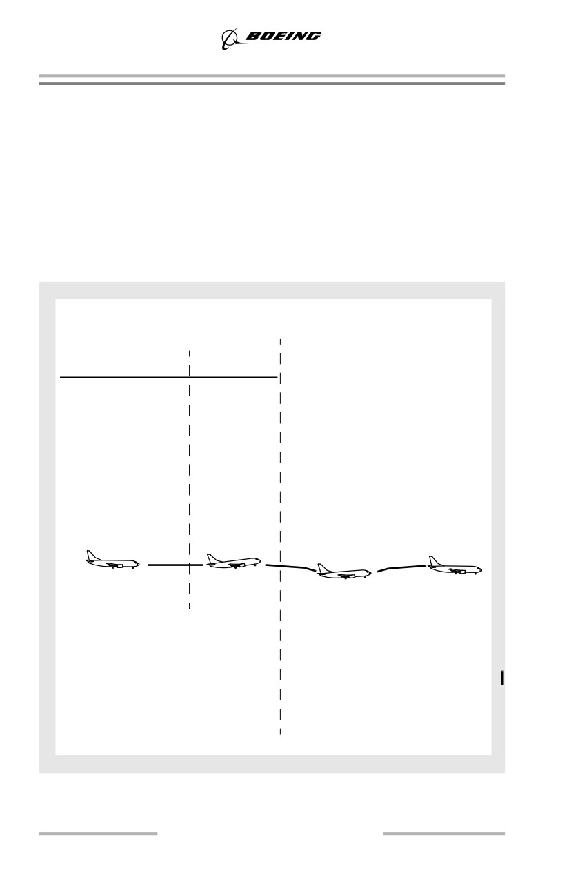
Approach to Stall Recovery
Initial Conditions
Approach
Recovery
If ground contact is not a factor
At buffet or stick shaker:
Flaps Gear Bank
Target% N1*
• Apply maximum thrust
Up
Up
0°
35 - 45%
• Smoothly decrease pitch
15
Dn
25°
60 - 70%
attitude to approximately 5°
above the horizon
30
Dn
0°
60 - 70%
• Level wings
• Accelerate to maneuvering
*Approximate
speed for flap position
power settings
• Stop descent and return to
to achieve a
target altitude
1 kt/sec
deceleration
• At altitudes above 20,000 feet,
pitch attitudes less than 5°
may be necessary to achieve
acceptable acceleration.
Maintain airplane in
Note pitch
Maneuver complete
trim until stick
attitude at
shaker or buffet
trim speed
If ground contact is a factor
At buffet or stick shaker:
• Apply maximum thrust
• Smoothly adjust attitude as
needed to avoid terrain
• Level wings
• Accelerate to maneuvering
speed for flap position
• Level off at target altitude.
7.8
Maneuvers
Command Speed
As the airplane is decelerated to the desired initial condition for the approach to
stall, set command speed to the maneuver speed for each selected flap setting. For
the approach to stall in the landing configuration, set command speed to VREF 30
+ 5 knots.
Initial Buffet-Stall Warning-Stall Buffet
The approach to stall recovery maneuver is entered with thrust that achieves an
airspeed decrease of approximately 1 knot per second.
During the initial stages of a stall, local airflow separation results in initial buffet
giving natural warning of an approach to stall. A stall warning is considered to be
any warning readily identifiable by the pilot, either artificial (stick shaker) or
initial buffet. Recovery from an approach to stall is initiated at the earliest
recognizable stall warning, initial buffet or stick shaker.
Lateral and Directional Control
Lateral control is maintained with ailerons. Rudder control should not be used
because it causes yaw and the resultant roll is undesirable.
Effect of Flaps
Flaps are used to increase low speed performance capability. The leading edge
devices ensure that the inboard wing stalls before the outboard wing. This causes
the nose of the airplane to pitch down at the onset of the stall.
Effect of Speedbrakes
For any airspeed, the angle of attack is higher with speedbrakes up. This increases
initial buffet speed and stick shaker speed but has a lesser effect on actual stall
speed.
Entry
To save time, thrust levers may be closed to allow a more rapid deceleration.
Target thrust for the configuration should be set approaching selected speed.
Some thrust is used during entry to provide positive engine acceleration for the
recovery. The airplane is maintained in trim while decelerating. Level flight or a
slight rate of climb is desired.
Landing Gear
If the entry has been made with the landing gear extended, do not retract it until
after the recovery.
7.9
Maneuvers
Flaps
Do not retract flaps during the recovery. Retracting the flaps from the landing
position, especially when near the ground, causes an altitude loss during the
recovery.
Recovery
Recover from approach to a stall with one of the following recommended recovery
techniques.
Ground Contact Not a Factor
At the first indication of stall (buffet or stick shaker) smoothly apply maximum
thrust, smoothly decrease the pitch attitude to approximately 5 degrees above the
horizon and level the wings. As the engines accelerate, counteract the nose up
pitch tendency with positive forward control column pressure and nose down trim.
(At altitudes above 20,000 feet, pitch attitudes of less than 5 degrees may be
necessary to achieve acceptable acceleration.)
Accelerate to maneuvering speed and stop the rate of descent. Correct back to the
target altitude.
Ground Contact a Factor
At the first indication of stall (buffet or stick-shaker) smoothly advance the thrust
levers to maximum thrust and adjust the pitch attitude as needed to avoid the
ground. Simultaneously level the wings. Control pitch as smoothly as possible. As
the engines accelerate, the airplane nose pitches up. To assist in pitch control, add
more nose down trim as the thrust increases. Avoid abrupt control inputs that may
induce a secondary stall. Use intermittent stick shaker as the upper limit for pitch
attitude for recovery when ground contact is a factor.
When ground contact is no longer a factor, continue to adjust pitch as required to
maintain level flight or a slight climb while accelerating to maneuvering speed for
the existing flap position.
Autopilot Engaged
If an approach to a stall is encountered with the autopilot engaged, apply limit
thrust and allow the airplane to return to the normal speed. At high altitude, it may
be necessary to initiate a descent to regain maneuvering speed. If autopilot
response is not acceptable, it should be disengaged.
7.10
Maneuvers
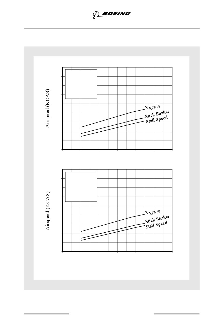
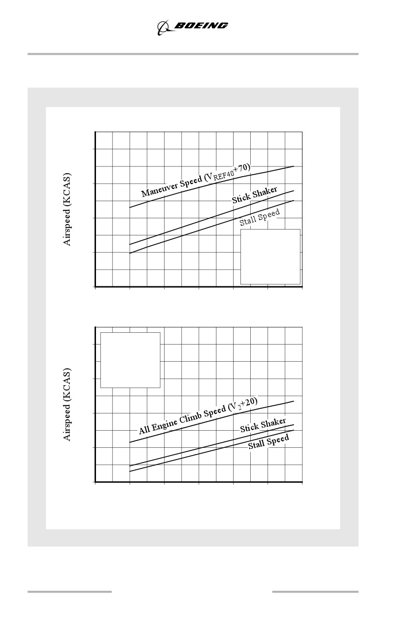
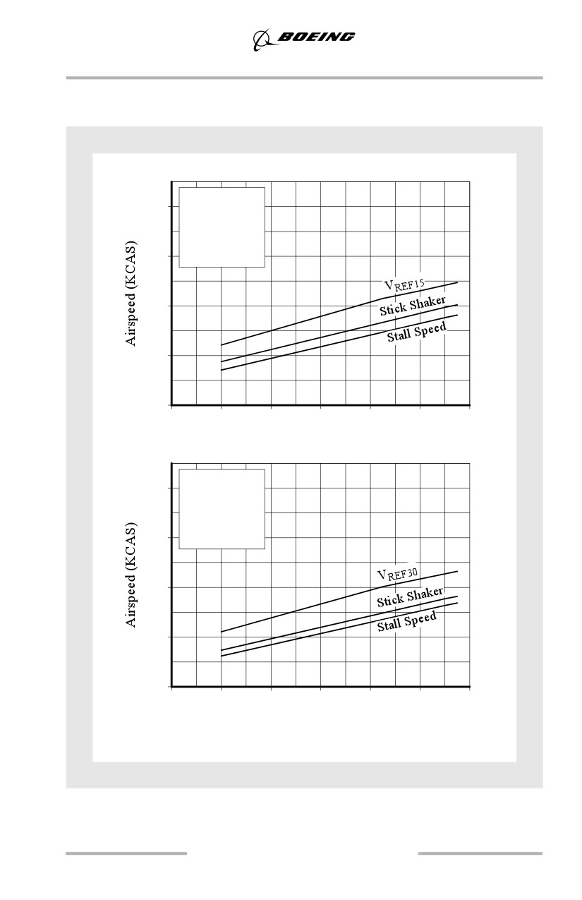
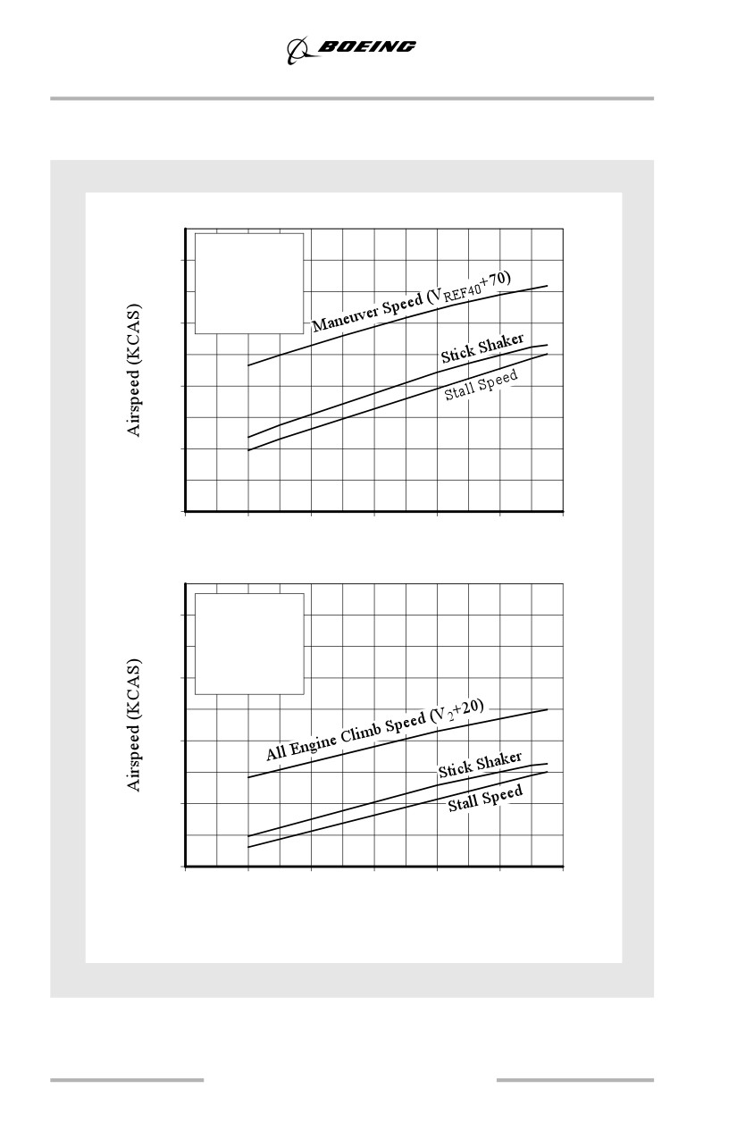
Stick Shaker and Stall Speeds
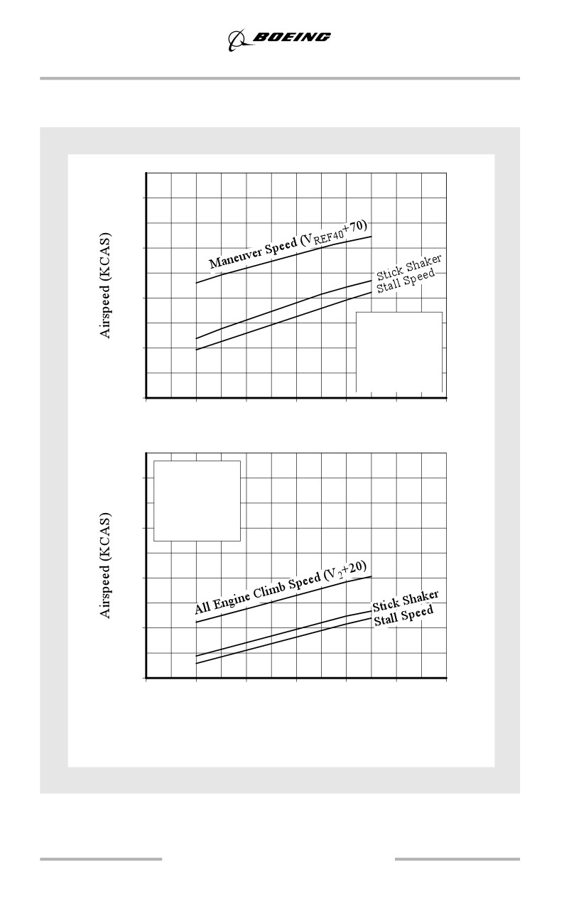
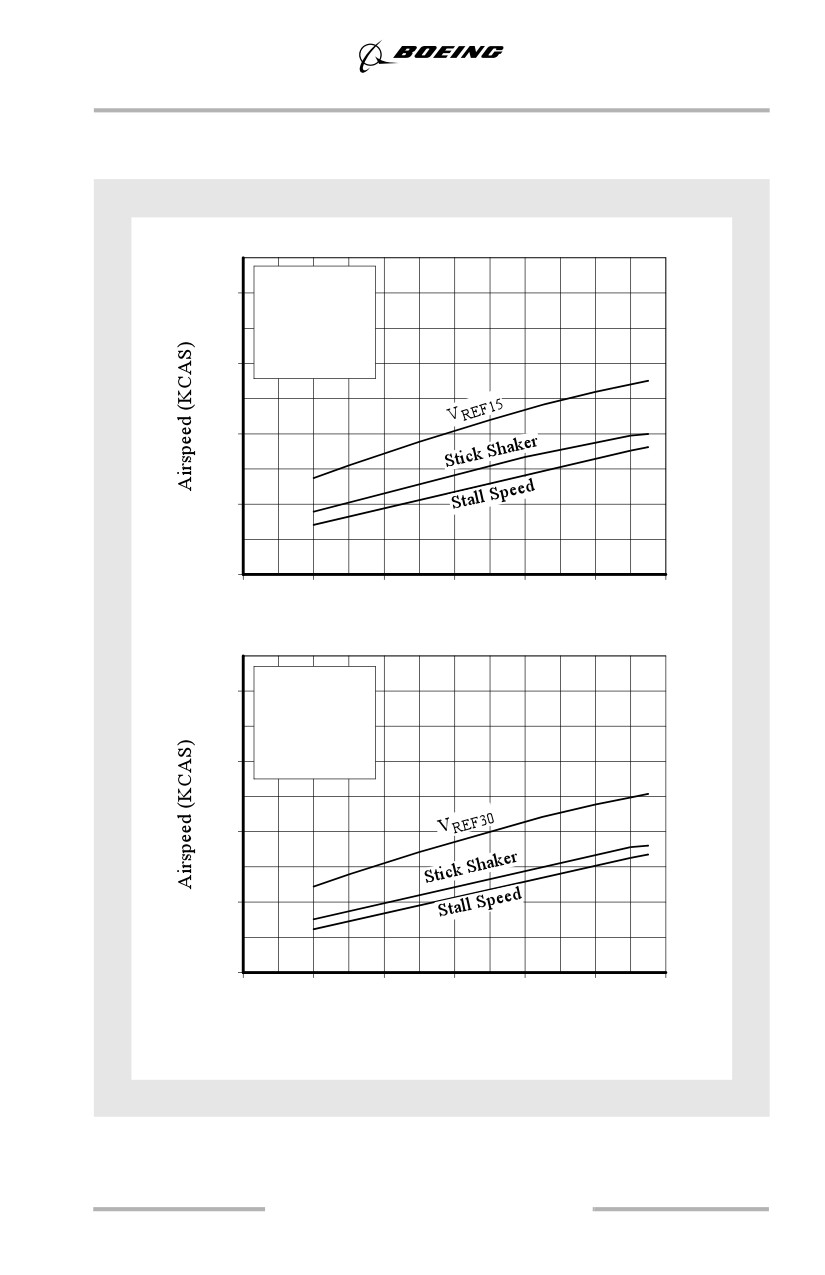
The following figures depict stick shaker and stall speeds at various gross weights
and flap settings. This data is presented for training purposes only.
7.11
Maneuvers
Stick Shaker and Stall Speeds
737-600
240
200
160
Flaps Up
Gear Up
120
10,000 Ft
Idle Thrust
Forward CG
80
60
80
100
120
140
160
180
(27.2)
(36.4)
(45.5)
(54.5)
(63.6)
(72.7)
(81.6)
Gross Weight - 1000 lbs (Kgs)
Flaps 5
240
Gear Up
10,000 Ft
Idle Thrust
200
Forward CG
160
120
80
60
80
100
120
140
160
180
(27.2)
(36.4)
(45.5)
(54.5)
(63.6)
(72.7)
(81.6)
Gross Weight - 1000 lbs (Kgs)
7.12
Maneuvers
Stick Shaker and Stall Speeds
737-600
Flaps 15
220
Gear Down
10,000 Ft
Idle Thrust
180
Forward CG
140
100
60
60
80
100
120
140
160
180
(27.2)
(36.4)
(45.5)
(54.5)
(63.6)
(72.7)
(81.6)
Gross Weight - 1000 lbs (Kgs)
Flaps 30
220
Gear Down
10,000 Ft
Idle Thrust
180
Forward CG
140
100
60
60
80
100
120
140
160
180
(27.2)
(36.4)
(45.5)
(54.5)
(63.6)
(72.7)
(81.6)
Gross Weight - 1000 lbs (Kgs)
7.13
Maneuvers
Stick Shaker and Stall Speeds
737-700
240
200
160
Flaps Up
Gear Up
120
10,000 Ft
Idle Thrust
Forward CG
80
60
80
100
120
140
160
180
(27.2)
(36.4)
(45.5)
(54.5)
(63.6)
(72.7)
(81.6)
Gross Weight - 1000 lbs (Kgs)
Flaps 5
240
Gear Up
10,000 Ft
Idle Thrust
200
Forward CG
160
120
80
60
80
100
120
140
160
180
(27.2)
(36.4)
(45.5)
(54.5)
(63.6)
(72.7)
(81.6)
Gross Weight - 1000 lbs (Kgs)
7.14
Maneuvers
Stick Shaker and Stall Speeds
737-700
Flaps 15
220
Gear Down
10,000 Ft
Idle Thrust
180
Forward CG
140
100
60
60
80
100
120
140
160
180
(27.2)
(36.4)
(45.5)
(54.5)
(63.6)
(72.7)
(81.6)
Gross Weight - 1000 lbs (Kgs)
Flaps 30
220
Gear Down
10,000 Ft
Idle Thrust
180
Forward CG
140
100
60
60
80
100
120
140
160
180
(27.2)
(36.4)
(45.5)
(54.5)
(63.6)
(72.7)
(81.6)
Gross Weight - 1000 lbs (Kgs)
7.15
Maneuvers
Stick Shaker and Stall Speeds
737-800
Flaps Up
240
Gear Up
10,000 Ft
Idle Thrust
200
Forward CG
160
120
80
60
80
100
120
140
160
180
(27.2)
(36.4)
(45.5)
(54.5)
(63.6)
(72.7)
(81.6)
Gross Weight - 1000 lbs (Kgs)
Flaps 5
240
Gear Up
10,000 Ft
Idle Thrust
200
Forward CG
160
120
80
60
80
100
120
140
160
180
(27.2)
(36.4)
(45.5)
(54.5)
(63.6)
(72.7)
(81.6)
Gross Weight - 1000 lbs (Kgs)
7.16
Maneuvers
Stick Shaker and Stall Speeds
737-800
Flaps 15
220
Gear Down
10,000 Ft
Idle Thrust
180
Forward CG
140
100
60
60
80
100
120
140
160
180
(27.2)
(36.4)
(45.5)
(54.5)
(63.6)
(72.7)
(81.6)
Gross Weight - 1000 lbs (Kgs)
Flaps 30
220
Gear Down
10,000 Ft
Idle Thrust
180
Forward CG
140
100
60
60
80
100
120
140
160
180
(27.2)
(36.4)
(45.5)
(54.5)
(63.6)
(72.7)
(81.6)
Gross Weight - 1000 lbs (Kgs)
7.17