Boeing 737 - 600/700/800/900. Flight Crew Training Manual (1999 year) - page 5
Approach and Missed Approach
Other Non-ILS Approaches
The MAP for all other non-ILS approaches is depicted on the approach chart. If
the procedure has a final approach fix, the MAP may be short of the runway
threshold, at the runway threshold, or located over a radio facility on the field. For
on airport facilities (VOR or NDB) which do not have a final approach fix, the
facility itself is the MAP and in most cases is beyond the runway threshold. Do
not assume the airplane will always be in a position to make a normal landing
when reaching the MDA(H) before reaching the MAP. When the MAP is at or
beyond the runway threshold, the airplane must reach MDA(H) before arrival at
the MAP if a normal final approach is to be made.
Precision Approach Radar (PAR)
The MAP for a PAR is the geographic point where the glide path intersects the
DA(H). Arrival at the MAP is determined by the pilot using the altimeter or as
observed by the radar controller, whichever occurs first.
Airport Surveillance Radar (ASR)
The radar controller is required to discontinue approach guidance when the
airplane is at the MAP or one mile from the runway, whichever is greater. Perform
the missed approach when instructed by the controller.
5.8
Approach and Missed Approach
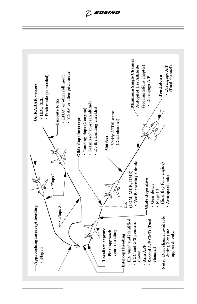
ILS Approach
ILS Approach - Fail Passive
5.9
Approach and Missed Approach
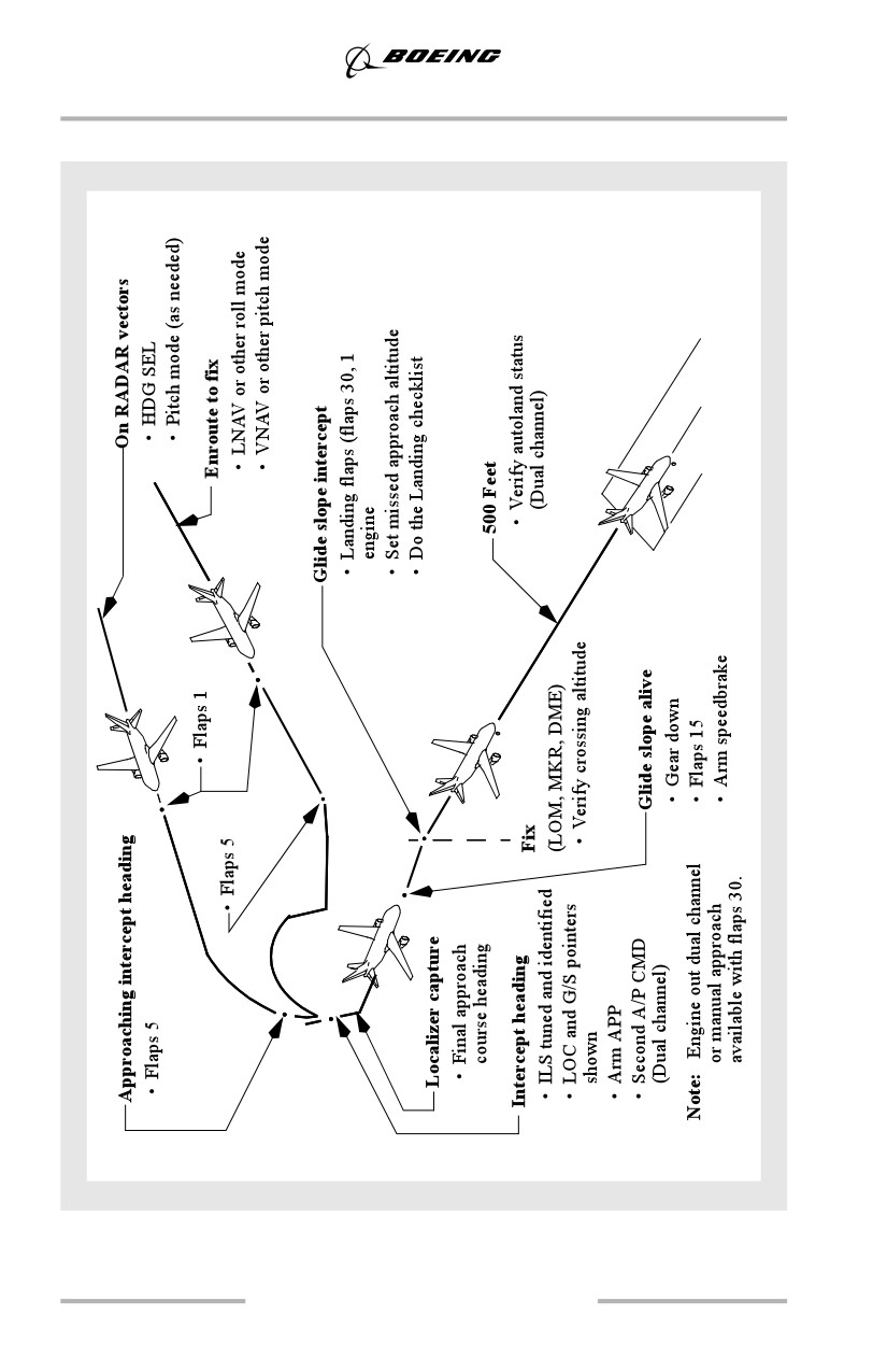
ILS Approach - Fail Operational
5.10
Approach and Missed Approach
ILS Approach - General
The ILS approach illustrated assumes all preparations for the approach such as
review of approach procedure and setting of minima and radios are complete. It
focuses on crew actions and avionic systems information. It also includes unique
considerations during low weather minima operations. The pattern may be
modified to suit local traffic and air traffic requirements.
Decision Altitude/Height - DA(H)
A Decision Altitude/Height is a specified altitude or height in a precision approach
where a missed approach must be initiated if the required visual reference to
continue the approach has not been established. The “Altitude” value is typically
measured by a barometric altimeter and is the determining factor for minima for
Category I approaches, (e.g., ILS, GLS, or RNAV with VNAV). The “Height”
value specified in parenthesis, typically a RA height above the touchdown zone
(HAT), is advisory. The RA may not reflect actual height above terrain.
For most Category II and Category III fail passive approaches, the Decision
Height is the controlling minima and the altitude value specified is advisory. A
Decision Height is usually based on a specified radio altitude above the terrain on
the final approach or touchdown zone.
Alert Height - AH
Alert heights are normally used for fail operational Category III operations. Alert
height is a height above the runway, above which a Category III approach must be
discontinued and a missed approach initiated if a specified failure occurs. For a
discussion on specified failures, see the AFDS Faults section, this chapter. Radio
altimeters are set in accordance with the airline's policy or at alert height to assist
in monitoring autoland status. Most regulatory agencies do not require visual
references below alert height.
Fail Operational
Fail operational refers to an AFDS capable of completing an ILS approach,
autoland, and rollout following the failure of any single system component after
passing alert height.
Fail Passive
Fail passive refers to an AFDS which in the event of a failure, causes no
significant deviation of airplane flight path or attitude. A DA(H) is used as
approach minimums.
5.11
Approach and Missed Approach
Procedure Turn and Initial Approach
Cross the procedure turn fix at flaps 5 maneuvering airspeed. If a complete arrival
procedure to the localizer and glide slope capture point has been selected via the
CDU, the initial approach phase may be completed using LNAV and VNAV.
Approach
Both pilots should not be “heads-down” during the approach. In some cases, such
as high density traffic, or when an arrival procedure is used only for reference,
revising the FMS flight plan may not be appropriate.
If displaying the arrival procedure is not desired, perform a “DIRECT TO” or
“INTERCEPT COURSE TO” the FAF, OM, or appropriate fix, to simplify the
navigation display. This provides:
• a display of distance remaining to the FAF, OM, or appropriate fix
• a depiction of cross track error from the final approach course
• LNAV capability during the missed approach procedure.
The approach procedure may be flown using HDG SEL or LNAV for lateral
tracking and VNAV, LVL CHG, or V/S for altitude changes. VNAV is the
preferred descent mode when the FMS flight plan is programmed for the intended
arrival. When VNAV is not available, use LVL CHG for altitude changes greater
than 1,000 feet. For smaller altitude changes, V/S permits a more appropriate
descent rate.
When maneuvering to intercept the localizer, decelerate and extend flaps to 5.
Attempt to be at flaps 5 and flaps 5 maneuvering speed before localizer capture.
When operating in speed intervention (as installed) or an autothrottle SPD mode,
timely speed selections minimize thrust lever movement during the approach.
This reduces cabin noise levels and increases fuel efficiency. When flaps are
extended, select the next lower speed just as the additional configuration drag
takes effect.
Delaying the speed selection causes an increase in thrust, while selecting the lower
speed too quickly causes thrust to decrease, then increase.
During the approach, adjust the map display and range to provide a scaled plan
view of the area. When on an intercept heading and cleared for the approach,
select the APP mode and observe the VOR/LOC and G/S flight mode
annunciations are armed.
APP mode should not be selected until:
• the ILS is tuned and identified
• the airplane is on an inbound intercept heading
• both localizer and glide slope pointers appear on the attitude display in the
proper position
• clearance for the approach has been received.
5.12
Approach and Missed Approach
The glide slope may be captured before the localizer in some airplanes. The glide
slope may be captured from either above or below. To avoid unwanted glide slope
capture, LOC mode may be selected initially, followed by the APP mode.
When using LNAV to intercept the final approach course, ensure raw data
indicates localizer interception to avoid descending on the glide slope with LOC
not captured. If needed, use HDG SEL to establish an intercept heading to the final
approach course.
Final Approach
The pilots should monitor the quality of the approach, flare, and landing (and
rollout for airplanes with automatic rollout capability) including speedbrake
deployment and autobrake application.
Note: The APP mode should be selected, both autopilots engaged in CMD, and
the airplane stabilized on the localizer and glide path before descending
below 800 feet RA.
At localizer capture, select the heading to match the inbound course. For normal
localizer intercept angles, very little overshoot occurs. Bank angles up to 30° may
be commanded during the capture maneuver. For large intercept angles some
overshoot can be expected.
Use the map display to maintain awareness of distance to go to the final approach
fix. When the glide slope pointer begins to move (glide slope alive), extend the
landing gear, select flaps 15, and decrease the speed to flaps 15 speed.
At glide slope capture, observe the flight mode annunciations for correct modes.
At this time, select landing flaps and VREF + 5 knots or VREF + wind correction
if landing manually, and do the Landing checklist. When using the autothrottle to
touchdown, no additional wind correction is required to the final approach speed.
The pilot monitoring should continue standard callouts during final approach and
the pilot flying should acknowledge callouts.
When established on the glide slope, set the missed approach altitude in the
altitude window of the MCP. Extension of landing flaps at speeds in excess of
flaps 15 speed may cause flap load relief activation and large thrust changes.
Check for correct crossing altitude and begin timing, if required, when crossing
the final approach fix (FAF or OM).
5.13
Approach and Missed Approach
There have been incidents where airplanes have captured false glide slope signals
and maintained continuous on glide slope indications as a result of an ILS ground
transmitter erroneously left in the test mode. False glide slope signals can be
detected by crosschecking the final approach fix crossing altitude and VNAV path
information before glide slope capture. A normal pitch attitude and descent rate
should also be indicated on final approach after glide slope capture. Further, if a
glide slope anomaly is suspected, an abnormal altitude range-distance relationship
may exist. This can be identified by crosschecking distance to the runway with
altitude or crosschecking the airplane position with waypoints indicated on the
navigation display. The altitude should be approximately 300 feet HAT per NM of
distance to the runway for a 3° glide slope.
If a false glide slope capture is suspected, perform a missed approach if visual
conditions cannot be maintained.
Below 1,500 feet radio altitude, the flare mode is armed. The FLARE
annunciation indicates the second autopilot is fully engaged. As the lowest
weather minimums are directly related to the system status, both pilots must
observe the FLARE annunciation.
For fail operational airplanes, verify ROLLOUT is armed and LAND 3 or LAND
2 is annunciated.
Check that the A/P disengage warning light on each instrument panel is
extinguished at 500 feet.
For fail operational airplanes, if an autoland annunciation changes or system fault
occurs above AH that requires higher weather minimums (reversion to LAND 2
or NO AUTOLAND), do not continue the approach below these higher minimums
unless suitable visual reference with the runway environment is established.
Airplanes with autopilots having fail operational capability are designed to safely
continue an approach below AH after a single failure of an autopilot element. The
autopilots protect against any probable system failure and safely land the airplane.
AFDS design provides for an AH of at least 200 feet HAT but may be modified to
a lower value by operators. The pilot should not interfere below AH unless it is
clearly evident pilot action is required.
During an autoland with crosswind conditions, fail passive airplanes will
touchdown in a crab. After touchdown, the rudder must be applied to maintain
runway centerline. The autopilots must be disengaged immediately after
touchdown. The control wheel should be turned into the wind as the autopilots are
disengaged. The A/T disengages automatically two seconds after touchdown.
5.14
Approach and Missed Approach
During an autoland with crosswind conditions, fail operational airplanes (LAND
2 or LAND 3 annunciated), the runway alignment maneuver uses forward slip to
reduce the crab angle of the airplane at touchdown. Alignment begins at 450 feet
radio altitude or lower, depending on the strength of the crosswind. The amount
of forward slip induced is limited to 5°. When a strong crosswind is present, the
airplane does not fully align with the runway, but lands with a slight crab angle. In
all cases, the upwind wing is low at touchdown.
The autobrakes should remain engaged until a safe stop is assured and adequate
visibility exists to control the airplane using visual references.
For fail operational airplanes, the autopilot and autobrakes should remain engaged
until a safe stop is assured and adequate visibility exists to control the airplane
using visual references.
Delayed Flap Approach (Noise Abatement)
If the approach is not being conducted in adverse conditions that would make it
difficult to achieve a stabilized approach, the final flap selection may be delayed
to conserve fuel or to accommodate speed requests by air traffic.
Intercept the glide slope with gear down and flaps 15 at flaps 15 speed. The thrust
required to descend on the glide slope may be near idle. Approaching 1,000 feet
AFE, select landing flaps, allow the speed to bleed off to the final approach speed,
then adjust thrust to maintain it. Do the Landing checklist.
Decision Altitude/Height - DA(H)
The pilot monitoring should expand the instrument scan to include outside visual
cues when approaching DA(H). Do not continue the approach below DA(H)
unless the airplane is in a position from which a normal approach to the runway
of intended landing can be made and suitable visual reference can be maintained.
Upon arrival at DA(H), or any time thereafter, any of the above requirements are
not met, immediately execute the missed approach procedure. When visual
contact with the runway is established, maintain the glide path to the flare. Do not
descend below the glide path.
Raw Data - (No Flight Director)
Raw data approaches are normally used during training to improve the instrument
scanflow. If a raw data approach is required during normal operations, refer to the
DDG or airline equivalent for the possibility of increased landing minima.
ILS deviation is displayed on the attitude display. ILS deviation may also be
displayed on the navigation display by selecting an ILS mode on the EFIS Control
Panel. The localizer course deviation scale on the attitude indicator remains
normal scale during the approach. Continue to cross-check the map display
against the attitude indicator raw data.
5.15
Approach and Missed Approach
The magnetic course/bearing information from the VOR/ADF pointers on the
navigation display may be used to supplement the attitude display localizer
deviation indication during initial course interception. Begin the turn to the
inbound localizer heading at the first movement of the localizer pointer.
After course intercept, the track line and read-out on the navigation display may
be used to assist in applying proper drift correction and maintaining desired
course. Bank as needed to keep the localizer pointer centered and the track line
over the course line. This method automatically corrects for wind drift with very
little reference to actual heading required.
Large bank angles are rarely required while tracking inbound on the localizer. Use
5° to 10° of bank angle.
When the glide slope pointer begins to move (glide slope alive), lower the landing
gear, extend flaps 15, and decelerate to flaps 15 speed. Intercepting the glide slope,
extend landing flaps and establish the final approach speed. When established on
the glide slope, preset the missed approach altitude in the altitude window. On
final approach, maintain VREF + 5 knots or an appropriate correction for
headwind component. Check altitude crossing the FAF. Begin timing, if required.
To stabilize on the final approach speed as early as possible, it is necessary to
exercise precise speed control during the glide slope intercept phase of the
approach. The rate of descent varies with the glide slope angle and groundspeed.
Expeditious and smooth corrections should be made based on the ILS course and
glide slope indications. Apply corrections at approximately the same rate and
amount as the flight path deviations.
The missed approach procedure is the same as a normal missed approach. Flight
Director guidance appears if TO/GA is selected. Refer to Go-Around and Missed
Approach - All Approaches, this chapter.
AFDS Autoland Capabilities
Refer to the applicable AFM for a description of demonstrated autoland
capabilities.
5.16
Approach and Missed Approach
Both hydraulic systems A and B must be operational when initiating a Category
III autoland approach. However, for fail operational airplanes during fail
operational approaches, if a hydraulic system becomes inoperative below alert
height, the automatic approach may be continued through landing and rollout. The
pilot should not intervene unless it is clearly evident that pilot action is required.
Note: For autoland use flaps 30 or 40. For airplanes equipped with a fail
operational autopilot using either LAND 3 or LAND 2, engine inoperative
autoland may be used with flaps 30 if airplane performance permits.
Note: Autoland should not be attempted unless the final approach course path is
aligned with the runway centerline. If the localizer beam is offset from the
centerline the AFDS may cause the airplane to depart the runway.
ILS Performance
Most ILS installations are subject to signal interference by either surface vehicles
or aircraft. To prevent this interference, ILS critical areas are established near each
localizer and glide slope antenna. In the United States, vehicle and aircraft
operations in these critical areas are restricted any time the weather is reported less
than 800 foot ceiling and/or visibility is less than 2 miles.
Flight inspections of ILS facilities do not necessarily include ILS beam
performance inside the runway threshold or along the runway unless the ILS is
used for Category II or III approaches. For this reason, the ILS beam quality may
vary and autolands performed from a Category I approach at these facilities should
be closely monitored.
Flight crews must remember that the ILS critical areas are usually not protected
when the weather is above 800 foot ceiling and/or 2 mile visibility. As a result,
ILS beam bends may occur because of vehicle or aircraft interference. Sudden and
unexpected flight control movements may occur at a very low altitude or during
the landing and rollout when the autopilot attempts to follow the beam bends. At
ILS facilities where critical areas are not protected, flight crews should be alert for
this possibility and guard the flight controls (control wheel, rudder pedals and
thrust levers) throughout automatic approaches and landings. Be prepared to
disengage the autopilot and manually land or go-around.
For fail operational airplanes, the AFDS includes a monitor to detect significant
ILS signal interference. If localizer or glide slope signal interference is detected
by the monitor, the autopilot disregards erroneous ILS signals and remains
engaged in an attitude stabilizing mode based on inertial data. Most ILS signal
interferences last only a short period of time, in which case there is no
annunciation to the flight crew other than erratic movement of the ILS raw data
during the time the interference is present. No immediate crew action is required
unless erratic or inappropriate autopilot activity is observed.
5.17
Approach and Missed Approach
Autolands on Contaminated Runways - Fail Operational Airplanes
AFDS ROLLOUT mode performance cannot be assured when used on
contaminated runways. The ROLLOUT mode relies on a combination of
aerodynamic rudder control, nose wheel steering and main gear tracking to
maintain the runway centerline using localizer signals for guidance. On a
contaminated runway, nose wheel steering and main gear tracking effectiveness,
and therefore airplane directional control capability, is reduced. To determine the
maximum crosswind, use the most restrictive of the autoland crosswind
limitation, or during low visibility approaches, the maximum crosswind
authorized by the controlling regulatory agency. Consideration should also be
given to the Landing Crosswind Guidelines published in chapter 6 of this manual
or operator guidelines.
If an autoland is accomplished on a contaminated runway, the pilot must be
prepared to disengage the autopilot and take over manually should ROLLOUT
directional control become inadequate.
Low Visibility Approaches
A working knowledge of approach lighting systems and regulations as they apply
to the required visual references is essential to safe and successful approaches.
Touchdown RVR is normally controlling for Category I, II, and III approaches.
For Category I and II approaches, mid and rollout RVR are normally advisory. For
Category III operations mid and rollout RVR may be controlling. In some
countries, visibility is used instead of RVR. Approval from the regulatory agency
is required to use visibility rather than RVR.
During Category I approaches, visual reference requirements typically specify
that either the approach lights or other aids be clearly visible to continue below
DA(H). During Category I and II approaches, descent below 100 ft. above
touchdown zone elevation requires the red terminating bars or red side row bars
(ALSF or Calvert lighting systems, or ICAO equivalent, if installed) to be
distinctly visible. If actual touchdown RVR is at or above the RVR required for the
approach, the runway environment (threshold, threshold lights and markings,
touchdown zone, touchdown lights and markings) should become clearly visible
resulting in a successful approach. After acquiring the red terminating bars or red
side row bars, if the runway environment does not become distinctly visible
execute an immediate missed approach.
Category III operations using fail passive autoland systems typically reach a DH
of 50 ft. when approaching the threshold. In this instance, regulations require that
the runway environment be clearly visible. If not, execute an immediate missed
approach.
Category III operations using fail operational autoland systems normally do not
require specific visual references below AH.
5.18
Approach and Missed Approach
A review of the approach and runway lighting systems available during the
approach briefing is recommended as the pilot has only a few seconds to identify
the lights required to continue the approach. For all low visibility approaches, a
review of the airport diagram, expected runway exit, runway remaining lighting
and expected taxi route during the approach briefing is recommended.
Regulatory agencies may require an additional 15% be added to the dry landing
distance. Agencies may also require wind speed limitations less than maximum
autoland wind speeds found in the FCOM.
AFDS System Configuration
The system configurations listed in this section may not include all of the systems
and equipment required for each type of operation. The AFM or operating
regulations may prescribe additional systems such as autobrakes, autothrottle or
rain removal.
More detailed information concerning Category II and Category III operational
requirements can be found in FAA advisory circulars or similar documents from
other regulatory agencies.
Category II Operations
Category II approaches may be conducted using single or dual autopilots, or flight
director only, with two engines. For single autopilot operation, the autopilot must
be disengaged no lower than the minimum altitude listed in the Limitations
Chapter of the FCOM. The autothrottles should be disconnected when the
autopilot is disengaged.
Category II Approach Autopilot
The following equipment must be operative for an automatic approach requiring
the use of Category II minima:
•
1 (or more) autopilots engaged
•
2 independent sources of electrical power. (The APU may be a substitute
source of power for the left or right electrical system.)
•
2 ADIRU's associated with the engaged autopilot in Nav mode
•
2 attitude indicators including attitude, radio altitude, ILS deviation,
DA(H) indication and AFDS status
• both engines operating
• FMA for each pilot.
5.19
Approach and Missed Approach
Category II Approach Flight Director
The following equipment must be operative for a Flight Director (FD) approach
requiring the use of Category II minima:
•
2 independent sources of electrical power. (The APU may be a substitute
source of power for the left or right electrical system.)
•
2 attitude indicators supplied by different symbol generators including
attitude, radio altitude, ILS deviation, DA(H) indication and AFDS status
•
2 separate flight directors, selected
•
2 ADIRU's in Nav mode
• FMA for each pilot
• both engines operating.
Category III Operations
Category III operations are typically based on an approach to touchdown using the
automatic landing system. Normal operations should not require pilot
intervention. However, pilot intervention should be anticipated in the event
inadequate airplane performance is suspected, or when an automatic landing
cannot be safely accomplished in the touchdown zone. Guard the controls on
approach through landing and be prepared to take over manually, if required.
Note: For fail operational airplanes (airplanes with autopilot rollout guidance),
the controls should be guarded through the landing roll.
The fail operational airplane is certified for Category IIIb operations with two
engines operating for flaps 30 or 40 landing, or, when certified, with one engine
operating for flaps 30 landing.
Category IIIa/Autoland
For Category IIIa operations the following equipment must be operative and
FLARE arm (LAND 2 or LAND 3 for fail operational airplanes) annunciated:
•
2 independent sources of electrical power. (The APU generator may be a
substitute source of power for the left or right electrical system.)
•
2 autopilots engaged
•
2 attitude indicators supplied by different display electronic units
including attitude, radio altitude, ILS deviation, DA(H), and AFDS status
•
2 ADIRU's in Nav mode
• both engines operating (fail passive airplanes)
• one or two engines operating (fail operational airplanes)
•
2 hydraulic systems
• FMA for each pilot.
5.20
Approach and Missed Approach
Category IIIb/Autoland
For Category IIIb operations, visual reference is not normally a specific
requirement for continuation of the approach to touchdown.
For Category IIIb operations the following equipment must be operative and
LAND 3 annunciated:
• one or two engines operating (use Cat IIIa weather minimums for one
engine)
• FMA for each pilot
• autothrottle at the start of final approach
• approach minima display for each pilot
• autoland status annunciation on both pilot’s displays
• antiskid operational
• normal flight controls
• windshield wipers for each pilot.
AFDS Faults
Faults can occur at any point during an AFDS approach. Many non-normal
situations or scenarios are possible. The flight deck is designed so that a quick
analysis and decision can be made for virtually all non-normal or fault situations
using the Autopilot/Autothrottle indicators, flight mode annunciations, master
caution system and, for fail operational airplanes, autoland status annunciations.
For fail operational airplanes, faults leading to non-normal operations can be
divided into two categories:
• those occurring above AH
• those occurring at or below alert height.
If the flight crew is aware of the airplane equipment requirements for the
approach, the following can be used for any AFDS fault indication:
Above Alert Height
Immediately after recognizing the fault from the master caution system,
instrument flags, or engine indications, check autoland status annunciation.
• if the autoland status annunciation has not changed, and the equipment is
not required for the approach, (e.g., flight director), continue the approach
• if the autoland status annunciation has changed, or the equipment is
required for the approach, adjust to the appropriate higher minimums or
go-around.
At or Below Alert Height
For any FMA alert on a fail operational airplane, continue the approach to an
automatic landing and rollout unless NO AUTOLAND is displayed. The pilot
should not intervene unless it is clearly evident that pilot action is required.
5.21

Approach and Missed Approach
A thorough fault analysis was included as a part of the fail operational
certification. Below 200 feet AGL a safe landing and rollout can be made with any
probable failure conditions.
For fail operational airplanes, flight crew alerts (lights, or aurals) may occur at any
time during the approach. If a master caution or aural occurs below alert height,
do not disengage the autopilot unless the autopilot system is not controlling the
airplane adequately. Below alert height, the AFDS fail operational design protects
against any probable system failure and will safely land the airplane. The pilot
should not intervene below AH unless it is evident that pilot action is required. If
a fault affects the autothrottle or autobrakes, assume manual control of thrust and
braking. Accomplish related procedures for system faults after rollout is complete
and manual control of the airplane is resumed.
If the autopilot is unintentionally disengaged below alert height, the landing may
be completed if suitable visual reference is established. Be alert for a mistrim
condition.
If a go-around is initiated with the autopilot disengaged, press the TO/GA switch.
If the TO/GA switch is not pressed, the flight directors remain in the approach
mode.
Dual Autopilot Approach and Go-Around Warnings - Fail Passive
WARNING
When
Cause
Pilot Response
Steady red A/P
Below 800’ RA
Stabilizer out of
Disengage A/P and execute
disengage warning
during approach
trim
manual landing (see note)
light
or manual go-around
During GA
Elevator
Disengage A/P and execute
position not
manual level off
suitable for
OR
single autopilot
Select higher go-around
operation
altitude
No FLARE arm
500’ above field
Pitch and roll
Disengage A/P and execute
annunciation
elevation during
monitors may
manual landing (see note)
approach
not be enabled,
or manual go-around
or only first A/P
up is engaged
Flashing red A/P
Below 800’ RA
A/P
Execute manual landing or
disengage warning
during approach
disengagement
manual go-around
light and wailer
5.22

Approach and Missed Approach
WARNING
When
Cause
Pilot Response
Flashing red A/T
Anytime
A/T
Cancel A/T disengage
disengage warning
disengagement
warning and control thrust
light
levers manually
Flashing red
Below 500’
A/P disengages
Disengage autopilot and
Autoland Warning
or stab trim
execute manual landing
light (as installed)
warning occurs
(see note) or manual
go-around.
-------or-------
------------------
Below 200’
ILS deviation
warning occurs
Note: Execute manual landing only if suitable visual reference is established
or if alternate landing minima can be used.
5.23

Approach and Missed Approach
Dual Autopilot Approach and Go-Around Warnings - Fail Operational
Alert
Above 200 ft.
Below 200 ft.
During
During
AGL
AGL
Rollout
Go-Around
Flashing red A/P
*Execute
**Execute
Execute
Execute manual
disengage warning
manual
manual
manual
go-around
light
go-around
go-around
rollout
Steady red A/P
**Disconnect
**Disconnect
N/A
Disengage
disengage warning
and execute
and execute
autopilot and
light
go-around
go-around
execute a manual
go-around
Flashing red A/T
Continue with
Continue with
Continue
Continue with
disengage warning
manual thrust
manual thrust
rollout
manual thrust
light
control
control
control
Engine failure
*Execute
Continue
Continue
Continue
during approach
manual
approach
rollout
go-around
go-around
NO LAND 3
*Continue
N/A
N/A
N/A
or
approach
(inhibited)
LAND 2
adjust minima
as appropriate
or go-around
NO AUTOLAND
*Execute
N/A
N/A
N/A
go-around
(inhibited)
Flashing G/S or LOC Indicators
ILS Deviation Alert
*Execute
**Execute
N/A
N/A
go-around
go-around
VOR/LOC
*Execute
**Execute
Execute
Disengage
and/or
go-around
go-around
manual
autopilot and
G/S and A/P yellow
rollout
execute a manual
go-around
* If suitable visual reference is not established.
** If suitable visual reference is established, land.
ILS Approach/Landing Geometry
The following diagrams use these conditions:
• data is based on typical landing weight
• airplane body attitudes are based on flaps 30, VREF 30 + 5 and should be
reduced by 1° for each 5 knots above this speed
5.24
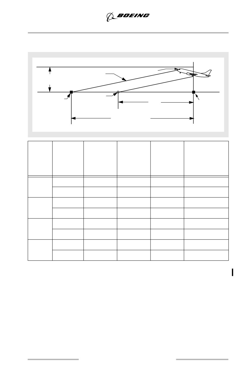
Approach and Missed Approach
• pilot eye height measured at point when main gear crosses threshold
• airplane ILS antenna crosses threshold at 50 feet.
Pilot Eye Height
ILS Glide Path
ILS Antenna
Height
Main Gear
Glide Slope
Threshold
Transmitter
Touchdown Point
to
Threshold
(No Flare)
Touchdown
954 ft. (3° GS)
1145 ft. (2.5° GS)
Model
Glide Path
Airplane
Main Gear
Pilot Eye
Threshold to
(deg)
Body
(feet)
Height
Main Gear
Attitude
(feet)
Touchdown
(deg)
Point - No Flare
(feet)
737
2.5
4.1
33
49
763
- 600
3.0
3.7
33
49
636
737
2.5
4.2
33
49
749
- 700
3.0
3.7
33
48
624
737
2.5
2.9
33
49
753
- 800
3.0
2.4
33
48
627
737
2.5
2.1
33
48
763
- 900
3.0
1.6
33
48
635
Non-Normal Operations
This section describes pilot techniques associated with engine inoperative
approaches. Techniques discussed minimize workload, improve crew
coordination, and enhance flight safety. However, a thorough review of applicable
Non-Normal Checklists associated with engine inoperative flight is a prerequisite
to understanding this section.
5.25
Approach and Missed Approach
One Engine Inoperative - Fail Passive Airplanes
AFDS management and associated procedures are similar to those used during the
normal ILS approach. Flight director (manual) or single autopilot may be used.
Weather minima for an ILS approach with one engine inoperative are specified in
the applicable AFM and/or the operator’s Operations Specification or equivalent.
Note: The airplane is approved for flight director or single autopilot operation to
Category I minimums with an engine initially inoperative if the airplane is
trimmed for the condition. The use of dual autopilots with an engine
inoperative is not authorized except for airplanes with a fail operational
autopilot.
During a single autopilot or flight director (manual) approach, the pilot must use
rudder pedal pressure to control yaw, followed by rudder trim to maintain an
in-trim condition during the entire approach. A centered control wheel indicates
proper trim.
Note: Use of the autothrottle for an approach with an engine inoperative is not
recommended.
Minimize thrust lever movements to reduce both asymmetry and speed changes.
Airplane configuration changes require little thrust change until capturing the
glide slope.
Intercept the localizer with flaps 5 at flaps 5 speed. When the glide slope is alive,
lower the landing gear, extend flaps to 15, set final approach speed, and decelerate.
Be prepared to take over manually in the event system performance is not
satisfactory.
One Engine Inoperative - Fail Operational Airplanes
With an engine inoperative, autoland operations are authorized for flaps 30
approach only. AFDS management and associated procedures are similar to those
used during the normal ILS approach. Refer to the PI chapter of the QRH for flaps
30 gear down, engine inoperative performance. If flaps 30 performance is not
satisfactory, a flaps 15 engine inoperative landing is required. Autoland operations
are not appropriate with flaps 15. Weather minima for an ILS approach with one
engine inoperative are specified in the applicable AFM and/or the operator’s
Operations Specification or equivalent.
5.26
Approach and Missed Approach
During a dual autopilot approach, the pilot must use rudder pedal pressure to
control yaw, followed by rudder trim to maintain an in-trim condition until LAND
2 or LAND 3 annunciates. When LAND 2 or LAND 3 annunciates, rudder inputs
are controlled by the autopilots. Directional control (yaw) is not affected by rudder
trim with the autopilots in the VOR/LOC or ROLLOUT modes.
Note: Use of autopilot and autothrottle is required during the flaps 30 engine
inoperative autoland approach.
Intercept the localizer with flaps 5 at flaps 5 speed. When the glide slope is alive,
lower the landing gear, extend flaps to 15. At glide slope capture, select flaps 30,
set VREF 30 + 5 knots.
Be prepared to take over manually in the event system performance is not
satisfactory.
Additional engine-out logic is incorporated during runway alignment to ensure the
downwind wing is not low at touchdown. If the crosswind is from the same side
as the failed engine, then the airplane is crabbed by inducing a sideslip. This
assures a 'wings-level' approach. For moderate or strong crosswinds from the
opposite side of the failed engine, no sideslip is induced as the failed engine high
approach configuration guarantees an upwind wing low touchdown characteristic.
Engine Inoperative, Rudder Trim - All Instrument Approaches
Rudder trim may be set to zero to facilitate directional control during thrust
reduction. This should be accomplished by 500 feet AFE to allow the PM ample
time to perform other duties and make appropriate altitude callouts.
Centering the rudder trim before landing allows most of the rudder pedal pressure
to be removed when the thrust of the operating engine is retarded to idle at
touchdown. Full rudder authority and rudder pedal steering capability are not
affected by rudder trim.
It may not be advisable to center the rudder trim due to crew workload and the
possibility of a missed approach. However, if touchdown occurs with the rudder
still trimmed for the approach, be prepared for the higher rudder pedal forces
required to track the centerline on rollout.
Engine Failure On Final Approach
737-600, 737-700
If an engine failure should occur on final approach with the flaps in the landing
position, the decision to continue the approach or execute a go-around should be
made immediately. If the approach is continued and sufficient thrust is available,
continue the approach with landing flaps. If the approach is continued and
sufficient thrust is not available for landing flaps, retract the flaps to 15 and adjust
thrust on the operating engine. Speed should be increased to 15 knots over the
previously set flaps 30 or 40 VREF. This is equal to at least VREF for flaps 15.
5.27
Approach and Missed Approach
737-800, 737-900
If an engine failure should occur on final approach with the flaps in the landing
position, the decision to continue the approach or execute a go-around should be
made immediately. If the approach is continued and sufficient thrust is available,
continue the approach with landing flaps. If the approach is continued and
sufficient thrust is not available for landing flaps, retract the flaps to 15 and adjust
thrust on the operating engine. Speed should be increased to 20 knots over the
previously set flaps 30 or 40 VREF. This is equal to at least VREF for flaps 15.
Note: For fail operational airplanes, if an engine fails below AH, the autoland and
rollout may continue.
If a go-around is required, follow the Go-Around and Missed Approach
procedures except use flaps 15 initially if trailing edge flaps are at 30 or 40.
Subsequent flap retraction should be made at a safe altitude and in level flight or
a shallow climb.
5.28
Approach and Missed Approach
Non - ILS Instrument Approaches
Non-ILS approaches are defined as:
• RNAV approach - an instrument approach procedure that relies on
airplane area navigation equipment for navigational guidance. The FMS
on Boeing airplanes is FAA-certified RNAV equipment that provides
lateral and vertical guidance referenced from an FMS position. The FMS
uses multiple sensors (as installed) for position updating to include GPS,
DME-DME, VOR-DME, LOC-GPS, and IRS.
• GPS approach - an approach designed for use by airplanes using
stand-alone GPS receivers as the primary means of navigation guidance.
However, Boeing airplanes using FMS as the primary means of
navigational guidance, have been approved by the FAA to fly GPS
approaches provided an RNP of 0.3 or smaller is used.
Note: A manual FMC entry of 0.3 RNP is required if not automatically
provided.
• VOR approach
• NDB approach
• LOC, LOC-BC, LDA, SDF, IGS, TACAN, or similar approaches.
Non-ILS approaches are normally flown using VNAV or V/S pitch modes or IAN.
Recommended roll modes are provided in the applicable FCOM procedure.
Non - ILS Instrument Approaches - General
Over the past several decades there have been a number of CFIT and unstabilized
approach incidents and accidents associated with non-precision (non-ILS)
approaches and landings. Many of these could have been prevented by the use of
constant angle approach methods. Traditional methods of flying non-ILS
approaches involve setting a vertical speed on final approach, leveling off at
step-down altitudes (if applicable) and at MDA(H), followed by a transition to a
visual final approach segment and landing. These traditional methods involve
changing the flight path at low altitudes and are not similar to methods for flying
ILS approaches. Further, these traditional methods often require of the crew a
higher level of skill, judgment and training than the typical ILS approach.
The following sections describe methods for flying non-ILS constant angle
approaches. These methods provide a constant angle approach, which reduces
exposure to crew error and CFIT accidents. These methods also make it much
easier for the crew to achieve a stabilized approach to a landing once suitable
visual reference to the runway environment has been established.
5.29
Approach and Missed Approach
A typical Instrument Approach using VNAV, IAN or V/S, as illustrated, assumes
all preparations for the approach; such as review of the approach procedure and
setting of minima and radio tuning have been completed. The procedures
illustrated focus generally on crew actions and avionics systems information. The
flight pattern may be modified to suit local traffic and air traffic requirements.
The following discussions assume a straight-in instrument approach is being
flown. A circling approach may be flown following an instrument approach using
VNAV, IAN or V/S provided the MCP altitude is set in accordance with the
circling approach procedure.
Types of Approaches
For airplanes not equipped with IAN, VNAV is the preferred method for
accomplishing non-ILS approaches that have an appropriate vertical path defined
on the FMC LEGS page. The section on Use of VNAV provides several methods
for obtaining an appropriate path, to include published glide paths, and where
necessary, a pilot constructed path. V/S may be used as an alternate method for
accomplishing non-ILS approaches.
Airplanes with IAN are capable of using the MCP APP switch to fly non-ILS
approaches that have an appropriate lateral and vertical path defined on the FMC
LEGS page. All IAN approaches provide the functions, indications, and alerting
features similar to an ILS approach while following FMC glide path. Although
non-ILS approaches using LNAV and VNAV can still be executed, IAN is
normally used in place of LNAV and VNAV because of improved approach
displays, alerts and standardized procedures.
Use of the Autopilot during Approaches
Automatic flight is the preferred method of flying non-ILS approaches. Automatic
flight minimizes flight crew workload and facilitates monitoring the procedure
and flight path. During non-ILS approaches, autopilot use allows better course and
vertical path tracking accuracy, reduces the probability of inadvertent deviations
below path, and is therefore recommended until suitable visual reference is
established on final approach.
Manually flying non-ILS approaches in IMC conditions increases workload and
does not take advantage of the significant increases in efficiency and protection
provided by the automatic systems. However, to maintain flight crew proficiency,
pilots may elect to use the flight director without the autopilot when in VMC
conditions.
Note: Currently, the VNAV PTH mode contains no path deviation alerting. For
this reason, the autopilot should remain engaged until suitable visual
reference has been established.
5.30
Approach and Missed Approach
Raw Data Monitoring Requirements
During localizer-based approaches; LOC, LOC-BC, LDA, SDF, and IGS,
applicable raw data must be monitored throughout the approach.
During non-localizer based approaches where the FMC is used for course or path
tracking (VOR, TACAN, NDB, RNAV, GPS, etc.), monitoring raw data is
recommended, if available.
During single FMC, single IRU, or single DME or single GPS operation, in the
event the single operational FMC, IRU, DME, or GPS fails during the FMC
approach, there must be a non-FMC means of navigation available for a missed
approach such as VOR/NDB raw data and/or radar, and there must be a non - FMC
approach available. Failure of the remaining single DME need not be considered
if GPS updating is being used.
Checking raw data for correct navigation before commencing the approach may
be accomplished by:
• pushing the POS switch on the EFIS control panel and comparing the
displayed raw data with the navaid symbols on the map. Example: The
VOR radials and raw DME data should overlay the VOR/DME stations
shown on the MAP and the GPS position symbol should nearly coincide
with the tip of the airplane symbol (FMC position)
• displaying the VOR and/or ADF pointers on the map display and using
them to verify your position relative to the map display.
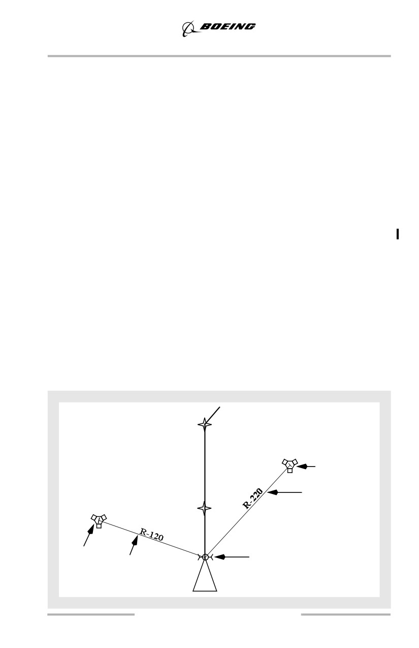
Typical Navigation Display
The following diagram represents a typical navigation display with the POS
display selected.
AMBOY
Raw data
DME
Raw data
VOR radial
JEFCO
Raw data
DME
Raw data
GPS position
VOR radial
5.31
Approach and Missed Approach
MAP Displays and Raw Data
The map mode should be used to the maximum extent practicable. The map
display provides a plan view of the approach, including final approach and missed
approach routing. The map increases crew awareness of progress and position
during the approach.
The map is particularly useful when the inbound course does not align with
runway centerline and allows the pilot to clearly determine the type of alignment
maneuver required. The map can be used to integrate weather radar returns, terrain
or traffic information within the approach path and airport area.
Note: When appropriate, compare airplane position on the map with ILS, VOR,
DME, and ADF systems to detect possible map shift errors. Use of the POS
function selectable on the EFIS control panel is the recommended method
for making this comparison. The VOR and ADF pointers should be
displayed on the map.
RNAV Approaches
RNAV approaches may be flown provided the RNP being used is equal to or less
than the RNP specified for the approach and is consistent with the AFM
demonstrated RNP capability.
Approach Requirements Relating to RNP
With appropriate operational approval, approaches requiring RNP alerting may be
conducted in accordance with the following provisions:
• AFM indicates that the airplane has been demonstrated for selected RNP
• at least one GPS or one DME is operational
• any additional GPS or DME requirements specified by Operations
Specification or by the selected terminal area procedure must be satisfied
• when operating with the following RNP values, or smaller:
Approach Type
RNP
NDB, NDB/DME
0.6 NM
VOR, VOR/DME
0.5 NM
RNAV
0.5 NM
GPS
0.3 NM
• no UNABLE REQD NAV PERF - RNP alert is displayed during the
approach
5.32
Approach and Missed Approach
Use of LNAV
To use LNAV for approaches and missed approaches, a proper series of
legs/waypoints that describe the approach route (and missed approach) must
appear on the LEGS page. There are two methods of loading these waypoints:
•
Database Selection
This method is required for RNAV and GPS approaches. An approach
procedure selected through the FMC ARRIVALS page provides the
simplest method of selecting proper waypoints. Procedures in the
database comply with obstruction clearance criteria for non-ILS
approaches.
No waypoints may be added or deleted between the FAF and the MAP. If
the approach to be flown is not in the database, another approach having
the same plan view may be selected. For example, an ILS procedure
might be selected if the plan view (route) is identical to an NDB approach.
In this case, waypoint altitudes must be checked and modified as required.
When an approach is flown by this "overlay" method, raw data should be
monitored throughout the approach to assure obstacle clearance.
Note: If an NDB approach for the desired runway is in the database, an
overlay approach should not be used.
If a waypoint is added to or deleted from a database procedure, FMC “on
approach” logic (as described in the FCOM) is partially or completely
disabled and the VNAV obstacle clearance integrity of the procedure may
be adversely affected. If an additional waypoint reference is desired, use
the FIX page and do not modify waypoints on the LEGS page.
•
Manual Waypoint Entry
Due to potentially inadequate terrain clearance, manual waypoint entry
should not be accomplished for RNAV or GPS approaches, nor should
this method be used with VNAV after the FAF.
When no procedure is available from the FMC ARRIVALS page, manual
entry of a series of waypoints may be accomplished to define the
approach routing. The waypoints may be conveniently defined by using
names of waypoints or navaids in the database, bearing/distance from
such fixes, intersections of radials or latitude/longitude information.
Procedure turns and DME arcs cannot usually be manually entered
(unless they can be defined by a series of waypoints). Deviation from the
defined route may require use of
“DIRECT TO” or “INTERCEPT
COURSE TO” when intercepting the inbound course. Constant
monitoring of raw data during the approach is required.
Note: Procedure turns and DME arcs may require use of HDG SEL.
5.33
Approach and Missed Approach
LNAV cannot be used to track fix or radial data displayed on the map that is not
part of the active route. A navaid/waypoint and the appropriate radial may be
inserted on the FIX page to create a “course” line on the map that helps to improve
situational awareness. A similar display may be created by manually tuning an
appropriate VOR and selecting the desired course. These methods provide
reference information on the map display only. They are not reflected on the
LEGS page and cannot be tracked with LNAV. These methods should only be used
when there is no opportunity to use an approach selected from the navigation
database and should therefore be considered only when normal means of
displaying approaches are not available. Pilots should be aware that the displayed
course is an FMC calculated course and is not raw data information.
Note: HDG SEL should be used to fly the approach ground track.
Note: VNAV PTH operation using speed intervention (as installed) is not
available with manually entered waypoints.
If the approach is not available in the NAV database, select the landing runway
from the FMC ARRIVALS page. The runway and associated extended centerline
then displays on the map to aid in maintaining position awareness.
Pilots should not become involved in excessive “heads down” FMC manipulation
to build map displays while at low altitude. Raw data VOR, ILS, and ADF
displays should be used to avoid distractions during higher workload phases of
flight. Map building should be avoided below 10,000 feet AGL.
Use of VNAV
Approaches using VNAV may be accomplished using any of the recommended
roll modes provided in the FCOM procedure.
5.34
Approach and Missed Approach
A vertical path suitable for use of VNAV is one that approximates 3° and crosses
the runway threshold at approximately 50 feet. To obtain such a VNAV path,
maximum use of the navigation database is recommended. For approaches where
an RNP is specified, or approaches where a DA(H) is used, the waypoints in the
navigation database from the FAF onward may not be modified except to add a
cold temperature correction, when appropriate, to the waypoint altitude
constraints. With respect to the construction of a suitable final approach path,
there are two types of approaches in the navigation database:
•
approaches with a glide path (GP) angle displayed on the final approach
segment of the LEGS page. The final approach segment is completely
compatible with VNAV and complies with final approach step down
altitudes (minimum altitude constraints).
•
approaches where no GP angle is published and where the approach end
of the runway is defined by a runway waypoint (RWxx) or a missed
approach point fix (MXxx or a named waypoint) exists. Normally these
waypoints display an approximate 50 foot threshold crossing altitude
constraint and may be used “as is” for VNAV. If the RWxx waypoint
altitude constraint does not coincide with approximately 50 feet, this
waypoint may be modified with a threshold crossing altitude of
approximately 50 feet.
Note: Threshold crossing altitude normally require entry of a four-digit
number. Example: enter 80 feet as 0080.
VNAV may be used for approaches modified in this way; however, the
approach should be flown by constant reference to raw data (VOR, NDB,
DME, etc.) and compliance with each minimum altitude constraint is
required. Use of a DA(H) is not appropriate when the final approach is
manually constructed in this manner.
ILS approaches coded with the appropriate threshold crossing height may
be used as an overlay for other approaches such as LOC or NDB.
VNAV should be used only for approaches that have one of the following features:
• a published GP angle on the LEGS page for the final approach segment
• an RWxx waypoint coincident with the approach end of the runway
• a missed approach waypoint before the approach end of the runway, (e.g.,
MXxx).
These features permit construction of a normal glide path. VOR approaches with
the missed approach point on the LEGS page beyond the runway threshold and
circling only approaches do not have these features.
5.35
Approach and Missed Approach
When appropriate, crews should make cold temperature altitude corrections by
applying a correction from an approved table to the waypoint altitude constraints.
The FMC obtains the GP angle displayed on the LEGS page from the navigation
database. This GP angle is based on the standard atmosphere and is used by the
FMC to calculate the VNAV path which is flown using a barometric reference.
When OAT is lower than standard, true altitudes are lower than indicated altitudes.
Therefore, if cold temperature altitude corrections are not made, the effective GP
angle is lower than the value displayed on the LEGS page. When cold temperature
altitude corrections are made, VNAV PTH operation and procedure tuning
function normally; however, the airplane follows the higher of the glide path angle
associated with the approach (if available) or the geometric path defined by the
waypoint altitude constraints.
Note: Temperature corrections redefine the glide path only if the FMC has the
geometric path option installed. Reference the applicable FCOM for
optional equipment installation.
When on final approach, VNAV may be used with speed intervention active (if
installed) to reduce workload. Adding speed constraints to the final approach
waypoints is not recommended because of the extra workload, lack of safety
benefit, and reduced ability to make last minute approach changes.
To prevent unnecessary level offs while descending in VNAV before the final
approach, reset the MCP altitude selector to the next lower constraint before
altitude capture, when compliance with the altitude restriction is assured.
Use of Altitude Intervention (As installed) during Approaches using VNAV
Altitude intervention is appropriate during approaches only if the AFDS enters
VNAV ALT mode above the approach path and descent must be continued.
Entering VNAV ALT mode can occur if passing a waypoint on the approach and
the crew has failed to reset the MCP altitude to a lower altitude. If this occurs, set
the MCP altitude to the next lower altitude constraint or the DA(H) or MDA(H),
as appropriate, and select altitude intervention. When VNAV altitude intervention
is selected, VNAV path deviation indications on the map display disappear
momentarily while the path is recalculated, but should reappear.
If altitude intervention is selected when on-approach logic is active, typically after
the airplane has sequenced the first approach waypoint, level flight is commanded
until reaching the VNAV path, then the airplane captures the VNAV path.
Note: When a PROC HOLD is active, VNAV altitude intervention functions
normally by causing the next waypoint altitude constraint to be deleted and
a descent to be initiated.
5.36
Approach and Missed Approach
Non - ILS Approach - One Engine Inoperative
Maneuvering before and after the final approach fix with one engine inoperative
is the same as for an all engine non-ILS approach.
Procedure Turn and Initial Approach
Cross the procedure turn fix at flaps 5 and flaps 5 maneuvering airspeed. If a
complete arrival procedure has been selected via the CDU, the initial approach
phase may be completed using LNAV and VNAV path, or other appropriate
modes.
Vertical Path Construction
This section describes typical final approach vertical profile (path) construction
criteria as they relate to flying instrument approaches using VNAV. This
information may also be useful to pilots who wish to fly the vertical path using
V/S.
Where there is a glide path (GP) angle coded in the navigation database, the FMC
builds the descent path upward and back in the direction of the FAF by starting at
the location of the missed approach waypoint (MAP) and its associated altitude
constraint. The FMC calculates this path using the coded GP angle, also called the
vertical angle. The MAP is normally shown on the LEGS page as a RWxx or
MXxx waypoint. In some cases a named waypoint is used as the MAP. A GP angle
is coded in the navigation database for nearly all straight-in approach procedures.
This GP angle is normally defined by the state authority responsible for the
approach procedure and provides a continuous descent at a constant flight path
angle for a final approach path that complies with minimum altitudes at
intermediate step down fixes. The typical GP angle is approximately 3.00°, but
can vary from 2.75° to 3.77°.
The projection of the vertical path upward and back toward the FAF along this
coded GP angle stops at the next higher limiting altitude in the vertical profile.
This limiting altitude is the more restrictive of the following:
• the “At” altitude on the constrained waypoint preceding the MAP
• the first approach waypoint for the selected approach procedure.
• the crossing altitude on the next “at or above” constrained waypoint
preceding the FAF
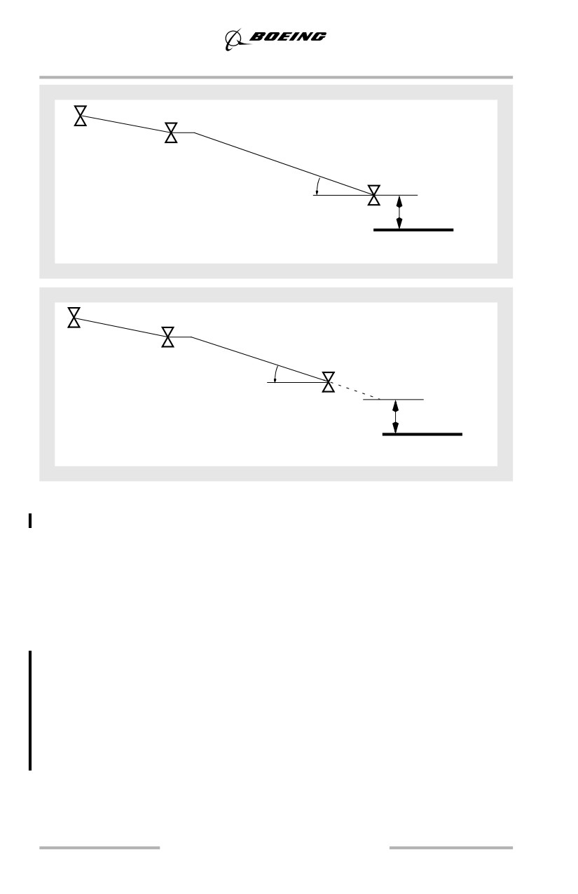
The following examples show typical VNAV final approach paths where there is
a GP angle in the navigation database. The first example shows an RWxx missed
approach waypoint. The second example below shows the VNAV final approach
path where there is a missed approach waypoint before the runway. Note that in
the second case the projected path crosses the runway threshold at approximately
50 feet. VNAV guidance is level flight, however, when the airplane passes the
missed approach point. Both examples are for “At” altitude constraints at the FAF.
5.37
Approach and Missed Approach
Coded vertical
angle
Threshold
FACF
FAF
MAP
crossing height
(RWxx)
Coded vertical
angle
Threshold
FACF
FAF
MAP
crossing height
(MXxx)
Note: The final approach course fix (FACF) is typically located on the final
approach course approximately 7 NM before the FAF. The FAF referred to
in the following procedures refers to the charted FAF and is intended to
mean the point at which the final approach descent is begun.
For the non-ILS approach procedures with an “At” constraint altitude at the FAF,
a short, level segment between the FAF and the final glide path (also called a
“fly-off”) may result. For the ILS procedure, the constraint altitude at the FAF is
computed to be the crossing altitude of the glide slope.
For procedures where both the FAF and FACF are coded with “at or above”
altitude constraints, the crew should consider revising the FACF altitude
constraint to “at” (hard constraint). This enables a shallower path before the FAF,
permitting a normal deceleration for flap and gear extension. Example: In the
diagram above, if both the FACF and the FAF contain “xxx/4000A” waypoint
constraints, the crew should change “4000A” to “4000” at the FACF to modify the
path for a more normal deceleration.
5.38
Approach and Missed Approach
Crews can expect to see several other variations of approach path construction:
• approaches where the FAF has an “at or above” waypoint altitude
constraint. The GP angle normally terminates at the FACF altitude
constraint or the cruise altitude, whichever is lower. When this type of
path is flown, the airplane passes above the FAF.
• where there is more than one GP angle, such as for ILS approaches, the
airplane uses the GP angle for the active leg to define the VNAV approach
path. These types of paths are shown on the LEGS page as having two GP
angle values, one approaching the FAF, the second approaching the
runway (missed approach point).
Note: The coded GP angle is steeper than normal in temperatures warmer than
ISA standard and is shallower than normal in temperatures colder than ISA
standard.
5.39
Approach and Missed Approach
Instrument Approach Using VNAV
5.40
Approach and Missed Approach
Approach Preparations for using VNAV
Select the approach procedure from the ARRIVALS page of the FMC. Tune and
identify appropriate navaids. Do not manually build the approach or add
waypoints to the procedure. If additional waypoint references are desired, use the
FIX page. To enable proper LNAV waypoint sequencing, select a straight-in
intercept course to the FAF when being radar vectored to final approach.
Verify/enter the appropriate RNP and set the DA(H) or MDA(H) using the baro
minimums selector. If required to use MDA(H) for the approach minimum
altitude, the barometric minimums selector should be set at MDA + 50 feet to
ensure that if a missed approach is initiated, descent below the MDA(H) does not
occur during the missed approach.
Note: The approach RNP is not displayed until 2 NM before the first waypoint
of the approach, including approach transitions, or when below 2,000 feet
above the airport, whichever occurs first unless the pilot manually enters
an RNP or the navigation data base specifies the RNP value.
Enter the appropriate wind correction on the APPROACH REF page or use speed
intervention, if available.
Transition to an Instrument Approach using VNAV
There are several techniques which help ensure a smooth descent transition to a
non-ILS final approach where VNAV PTH will be used.
Note: The FAF is normally the waypoint shown on the LEGS page and map
display just before the final approach segment. The following discussions
assume the FAF altitude constraint is set in the MCP while descending
toward the FAF.
If descending to FAF altitude in LVL CHG or V/S, or if in ALT HOLD at the FAF
altitude, set DA(H)/MDA(H) in the MCP and engage VNAV when approximately
2 NM before the FAF. Speed intervention (as installed) may also be engaged, if
desired. The airplane will descend on final approach in VNAV PTH.
If descending in VNAV PTH before final approach and the situation permits a
continuous descent through final approach, remain in VNAV PTH while
configuring the airplane for approach and landing. The airplane will slow
automatically to the maneuver speed for the current flap setting. Reset the MCP
to DA(H)/MDA(H) approximately 2 NM before the FAF (waypoint just before the
final approach segment) to prevent level off. Speed intervention (as installed) may
also be engaged, if desired.
5.41
Approach and Missed Approach
If descending in VNAV SPD, the AFDS will change to VNAV PTH automatically
when approaching the FAF if the airplane is on or below the path. Reset the MCP
to the DA(H)/MDA(H) approximately 2 NM before the FAF. If the AFDS enters
ALT HOLD mode beyond the FAF, set DA(H)/MDA(H) in the MCP and select
VNAV without delay. If VNAV ALT (as installed) has engaged beyond the FAF,
set DA(H)/MDA(H) in the MCP and select altitude intervention without delay to
enable continued descent on the final approach path. Execute a missed approach
if the deviation above path becomes excessive enough to prevent achieving a
stabilized approach.
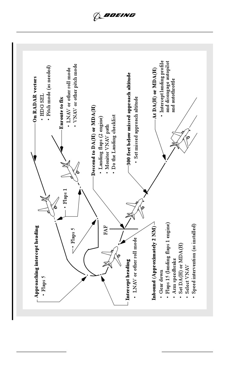
Final Approach using VNAV
Approaching intercept heading, select flaps 5 and select LNAV or other
appropriate roll mode. Approaching the FAF (approximately 2 NM), select gear
down and flaps 15. Adjust speed if using speed intervention. Set the DA(H) or
MDA(H) in the MCP altitude window, select VNAV, and ensure VNAV PTH and
appropriate roll mode is annunciated.
Note: If desired altitude is not at an even 100 foot increment, set the MCP altitude
to the nearest 100 ft. increment above the altitude constraint or MDA(H).
Just before the FAF, select landing flaps, slow to final approach speed and do the
Landing checklist. If the charted FAF is too close to the runway to permit a
stabilized approach, consider establishing final approach pitch mode and
configuring for approach and landing earlier than specified in the FCOM
procedure.
With the MCP altitude set to DA(H) or MDA(H) and the airplane stabilized on the
final approach path, the map altitude range arc assists in determining the visual
descent point (VDP). As soon as the airplane is at least 300 feet below the missed
approach altitude and stabilized on final approach in VNAV PTH, set the MCP
altitude to the missed approach altitude. VNAV path deviation indications on the
map display assist in monitoring the vertical profile. The autopilot tracks the path
in VNAV PTH resulting in arrival at, or near, the visual descent point by the
DA(H) or MDA(H).
Minimum Descent Altitude (MDA(H))/Decision Altitude (DA(H))
When specifically authorized by the instrument procedure and regulatory
authority, approaches may be flown to the following minima:
• a published VNAV DA(H)
• a published MDA(H) used as a decision altitude
When either of the above minima are not specifically authorized, use the MDA(H)
specified for the instrument procedure.
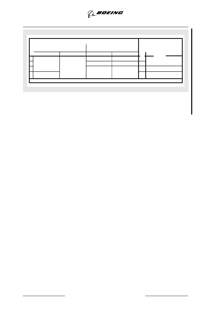
The following diagram illustrates an approach procedure containing DA(H) and
MDA(H) minimums for approaches using LNAV/VNAV or LNAV only.
5.42
Approach and Missed Approach
STRAIGHT-IN LANDING RWY 28R
CIRCLE - TO - LAND
LNAV/VNAV
LNAV
DA(H)740’(727’)
MDA(H) 1000’(987’)
ALS out
ALS out
Max
Kts
MDA(H)
A
RVR 40 or 3/4
RVR 60 or 11/4
90
B
/
120
1000’(987’) - 2
2
RVR 50 or 1
/
C
140
1140’(1027’) -3
/
3
D
/
165
1160’(1147’) -3
Note: Some non-ILS approaches specify a VNAV DA(H). Regulations may
require use of the autopilot in the VNAV PTH mode to permit use of the
DA(H).
When reaching the DA(H) or MDA(H), be prepared to disengage the autopilot,
disconnect the autothrottle and land or execute an immediate go-around.
Note: If using an MDA(H), initiating a missed approach approximately 50 feet
above MDA(H) may be necessary to avoid descending below the MDA(H)
during the missed approach, if required for the procedure or by the
regulatory authority.
The pilot monitoring should expand the instrument scan to include outside visual
cues when approaching DA(H) or MDA(H). Do not continue the approach below
DA(H) or MDA(H) unless the airplane is in a position from which a normal
approach to the runway of intended landing can be made and suitable visual
reference can be maintained. Upon arrival at DA(H) or MDA(H) or any time
thereafter, if any of the above requirements are not met, immediately execute the
missed approach procedure.
When suitable visual reference is established, maintain the descent path to the
flare. Do not descend below the visual glide path. While VNAV PTH guidance
may still be used as a reference once the airplane is below DA(H) or MDA(H), the
primary means of approach guidance is visual.
Note: VNAV path guidance transitions to level flight once the missed approach
fix is passed.
Simulated Instrument Approach Using VNAV
To maintain proficiency, crews may practice instrument approach using VNAV
procedures while flying ILS approaches as follows:
• ensure the ILS is tuned and identified and the ILS raw data is monitored
throughout the approach
• track the localizer using VOR/LOC or LNAV as the roll mode
5.43
Approach and Missed Approach
• use VNAV as the pitch mode to track the GP angle. The charted GP angle
normally coincides with the ILS glide slope angle
• disengage the autopilot by the minimum altitude specified in the
Limitations chapter of the FCOM.
Note: Limit the use of the above technique to VMC weather conditions.
In ambient temperature conditions warmer than ISA standard, the airplane may
remain slightly high relative to the ILS glide slope, and in temperatures colder
than ISA standard, the airplane may remain slightly lower than the ILS glide
slope. Discontinue use of this technique and manually track the localizer and glide
slope if localizer or glide slope deviations become unacceptable.
5.44
Approach and Missed Approach
Instrument Approach Using IAN (As installed)
5.45
Approach and Missed Approach
Use of IAN - General
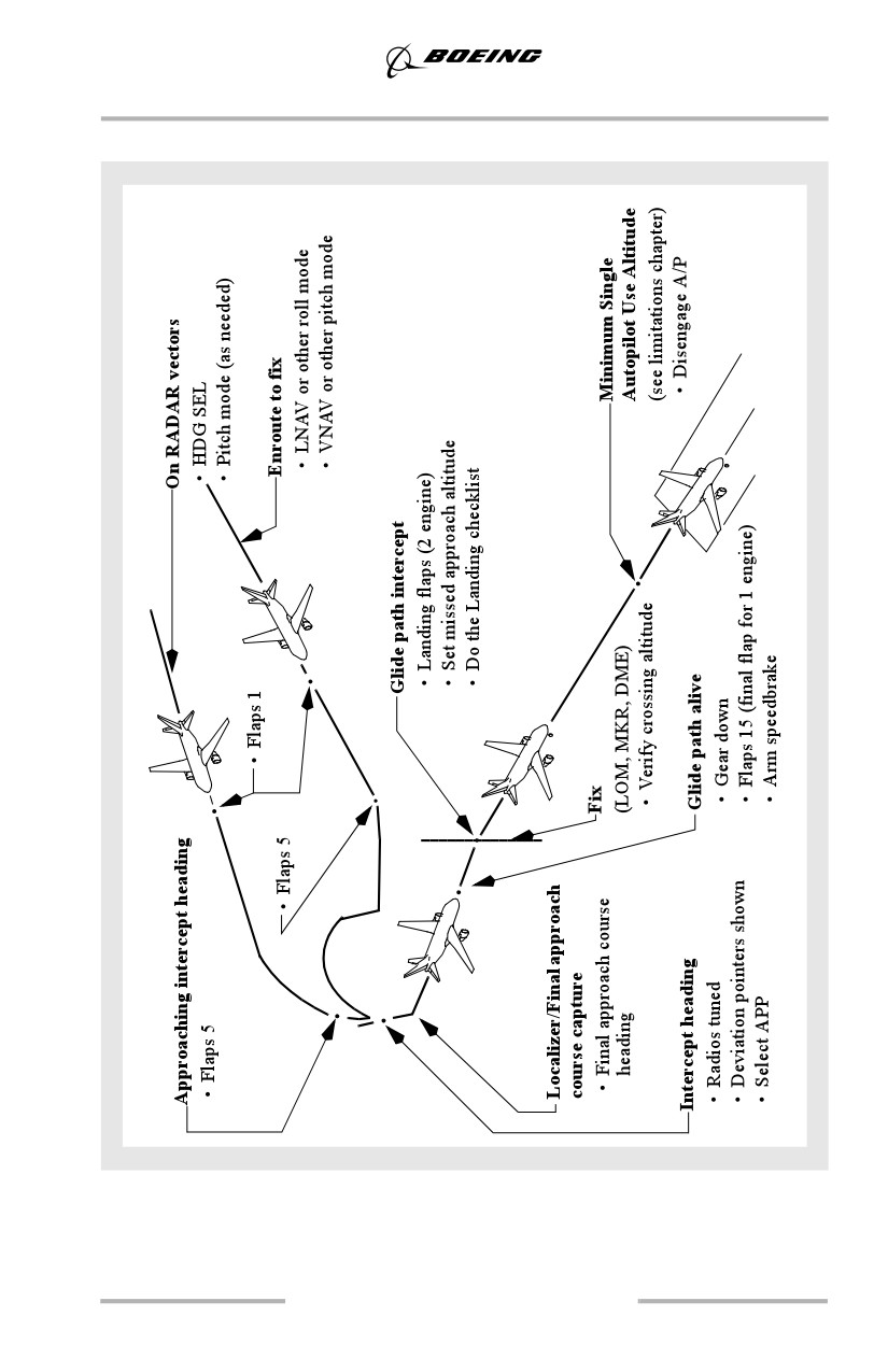
The approach profile illustrated depicts crew actions used during an approach
using Integrated Approach Navigation (IAN). Since IAN approach techniques are
similar to ILS approach techniques, only items considered unique to IAN are
discussed in the remainder of this section. The approach profile illustrated
assumes all preparations for the approach such as review of the approach
procedure and setting of minima and radios, as required, are complete.
Airplanes with IAN are capable of using the MCP APP switch to execute
instrument approaches based on flight path guidance from the navigation radios,
the FMC, or a combination of both. All IAN approaches provide the functions,
indications and alerting features similar to an ILS approach. Although non-ILS
approaches using LNAV and VNAV can still be performed, IAN is normally used
in place of LNAV and VNAV because of improved approach displays, alerts and
standardized procedures.
IAN approach types:
• RNAV
• GPS
• VOR approach
• NDB approach
• LOC, LOC-BC, LDA, SDF, TACAN, or similar approaches.
Note: IAN annunciations are not displayed on the HUD, standby ADI, or ISFD.
IAN Requirements and Restrictions
• airplanes must be equipped with FMC U10.5 or later and IAN FMA
displays
• dual or single engine approaches are authorized
• raw data monitoring is required during localizer based approaches.
During FMC based non-ILS approaches, raw data monitoring is
recommended when available in accordance with the techniques
described in the Non-ILS approach section in this chapter
• QFE operation is not authorized
• RNP appropriate for the approach must be used
• the autopilot is required until suitable visual reference is established when
performing an approach requiring an RNP of 0.15 or lower.
Flight Mode Annunciations and other IAN Features
FMAs vary depending on the source of the navigation guidance used for the
approach, navigation radio or FMC.
For localizer based approaches:
5.46

Approach and Missed Approach
Approach
FMA
ILS with G/S out, LOC, LDA, SDF
VOR/LOC and G/P
B/C LOC
BCRS and G/P
If the FMC is used for lateral (course) guidance:
Approach
FMA
GPS, RNAV
FAC and G/P
VOR, NDB, TACAN
FAC and G/P
Approach Preparations for using IAN
IAN may be used with the flight director, single autopilot, or flown with raw data.
The procedure turn, initial approach, and final approach are similar to the ILS.
For FMC based approaches, a proper series of legs/waypoints describing the
approach route including an appropriate vertical path or glide path (GP) angle
must appear on the LEGS page. A GP angle displayed on the LEGS page means
the vertical path complies with final approach step down altitudes (minimum
altitude constraints). A glide path angle suitable for an IAN approach is one that
approximates 3° and crosses the runway threshold at approximately 50 feet.
Waypoints in the navigation database from the FAF onward may not be modified.
Cold temperature altitude corrections are not permitted when using IAN.
The appropriate procedure must be selected in the FMC. If final approach course
guidance is derived from the localizer, the radios must be tuned to the appropriate
frequency. If final approach course guidance is derived from the FMC, radios must
be tuned to a VOR frequency.
Note: For all approaches, including B/C LOC approaches, the inbound front
course must be set in the MCP.
Final Approach using IAN
When cleared for the approach, select the approach mode. Before engagement of
the approach mode, grey lateral and vertical deviation pointers are displayed in
addition to the deviation pointers for engaged modes. These pointers show the
pilot the direction of the final approach course and glide path relative to the
airplane. As course and glide path capture occurs, the appropriate pointers turn
magenta.
Deviation scales are proportional to RNP. Similar to ILS localizer and glide slope
deviation scales, the IAN deviation scales become more sensitive as the airplane
approaches the runway.
5.47