Boeing 737 - 600/700/800/900. Flight Crew Training Manual (1999 year) - page 4

Takeoff and Initial Climb
Model
Flap
Liftoff Attitude
Minimum Tail
Tail Strike Pitch
(degrees)
Clearance
Attitude
inches (cm)
(degrees)
737-600
1
11.0
24 (61)
5
11.0
24 (61)
10
10.8
25 (64)
16.2
15
10.5
26 (66)
25
10.2
28 (71)
737-700
1
11.0
18 (46)
5
11.0
18 (46)
10
10.8
19 (48)
14.7
15
10.6
21 (53)
25
10.2
23 (58)
737-800
1
8.9
10 (25)
5
8.9
10 (25)
10
8.7
10 (25)
11.0
15
8.5
13 (33)
25
8.3
15 (38)
737-900
1
8.4
13 (33)
5
8.3
13 (33)
10
8.1
13 (33)
10.0
15
7.8
16 (41)
25
7.6
18 (46)
3.30
Takeoff and Initial Climb
Initial Climb - One Engine Inoperative
The initial climb attitude should be adjusted to maintain a minimum of V2 and a
positive climb. After liftoff the flight director provides proper pitch guidance.
Cross check indicated airspeed, vertical speed and other flight instruments. The
flight director commands a minimum of V2, or the existing speed up to a
maximum of V2 + 20.
If the flight director is not used, indicated airspeed and attitude become the
primary pitch references.
Retract the landing gear after a positive rate of climb is indicated on the altimeter.
The initial climb attitude should be adjusted to maintain a minimum of V2. If an
engine fails at an airspeed between V2 and V2 + 20, climb at the airspeed at which
the failure occurred. If engine failure occurs above V2 + 20, increase pitch to
reduce airspeed to V2 + 20 and maintain until flap retraction altitude.
The flight director roll mode commands wings level or HDG SEL (as installed)
after liftoff until LNAV engagement or another roll mode is selected. If ground
track is not consistent with desired flight path, use HDG SEL/LNAV to achieve
the desired track.
Indications of an engine fire, impending engine breakup or approaching or
exceeding engine limits, should be dealt with as soon as possible. Accomplish the
appropriate recall checklist items as soon as the airplane is under control, the gear
has been retracted and a safe altitude (typically 400 feet AGL or above) has been
attained. Accomplish the reference checklist items after the flaps have been
retracted and conditions permit.
If an engine failure has occurred during initial climb, accomplish the appropriate
checklist after the flaps have been retracted and conditions permit.
Immediate Turn after Takeoff - One Engine Inoperative
Obstacle clearance or departure procedures may require a special engine out
departure procedure. If an immediate turn is required, initiate the turn at the
appropriate altitude (normally at least 400 feet AGL). Maintain V2 to V2 + 15
with takeoff flaps while maneuvering.
Note: Limit bank angle to 15° until V2 + 15 knots. Bank angles up to 30° are
permitted at V2 + 15 knots with takeoff flaps.
After completing the turn, and at or above flap retraction altitude, accelerate and
retract flaps.
Autopilot Engagement - One Engine Inoperative
When at a safe altitude above 400 feet AGL with correct rudder pedal or trim
input, the autopilot may be engaged.
3.31
Takeoff and Initial Climb
Flap Retraction - One Engine Inoperative
The minimum altitude for flap retraction with an engine inoperative is 400 feet
AGL. During training, flap retraction is initiated at 1,000 feet AGL.
At engine out flap retraction altitude, select flaps up maneuvering speed on the
MCP. Engine-out acceleration and climb capability for flap retraction are
functions of airplane thrust to weight ratio. The flight director commands a near
level or a slight climb (0-200 fpm) flap retraction segment. Accelerate and retract
flaps on the flap-speed schedule.
If the flight director is not being used at flap retraction altitude, decrease pitch
attitude to maintain approximately level flight while accelerating. Retract flaps on
the flap-speed schedule.
As the airplane accelerates and flaps are retracted, adjust the rudder pedal position
to maintain the control wheel centered and trim to relieve rudder pedal pressure.
Flaps Up - One Engine Inoperative
After flap retraction and at flaps up maneuvering speed, select LVL CHG, set
maximum continuous thrust (CON) and continue the climb to the obstacle
clearance altitude.
Initiate the appropriate engine failure non-normal checklist followed by the After
Takeoff checklist when the flaps are up and thrust is set. Remain at flaps up
maneuvering speed until all obstructions are cleared, then select the engine-out
schedule from the CDU CLB page (depending on the next course of action).
Ensure the autothrottle is disconnected before reaching level off altitude. After
level off, set thrust as needed.
Noise Abatement - One Engine Inoperative
When an engine failure occurs after takeoff, noise abatement is no longer a
requirement.
Engine Failure During an ATM Takeoff
A reduced thrust takeoff using the ATM is based on a minimum climb gradient
that clears all obstacles with an engine failure after V1. If an engine failure occurs
during an ATM takeoff, based on takeoff performance data, it is not necessary to
set maximum thrust on the remaining engine. However, if maximum thrust is
desired during an ATM takeoff, thrust on the operating engine may be increased
to go-around thrust by manually advancing the thrust levers. The takeoff
performance data provides a safe operating margin for minimum control speed on
the ground (VMCG) when go-around thrust is set.
3.32
Takeoff and Initial Climb
Advancing the operating engine to the maximum takeoff thrust provides
additional performance margin. This additional performance margin is not a
requirement of the reduced thrust takeoff certification and its use is at the
discretion of the flight crew.
Engine Failure During a Fixed Derate Takeoff
During a fixed derate takeoff, the takeoff performance data at low gross weights
may not provide a safe operating margin for VMCG if thrust levers are advanced
beyond the fixed derate limit. A thrust increase following an engine failure,
especially near V1, could result in a loss of directional control and should not be
accomplished unless, in the opinion of the captain, terrain contact is imminent.
Engine Failure During a Combined Takeoff
During a combined fixed derate and ATM takeoff, the takeoff performance data is
based on the fixed derate takeoff thrust before the assumed temperature reduction.
The takeoff performance data provides a safe operating margin for minimum
control speed on the ground (VMCG) when the fixed derate takeoff thrust is
selected, but not beyond the fixed derate limit. A thrust increase beyond the fixed
derate limit following an engine failure, especially near V1, could result in a loss
of directional control and should not be accomplished unless, in the opinion of the
captain, terrain contact is imminent.
3.33
Takeoff and Initial Climb
Intentionally
Blank
3.34
Climb, Cruise, Descent and Holding
Chapter 4
Table of Contents
Section TOC
4.TOC Climb, Cruise, Descent and Holding-Table of Contents
Preface
4.1
Climb
4.1
Reduced Thrust Climb
4.1
Climb Constraints
4.1
Low Altitude Level Off
4.2
Transition to Climb
4.2
Climb Speed Determination
4.3
Engine Icing During Climb
4.3
Economy Climb
4.3
Economy Climb Schedule - FMC Data Unavailable
4.4
Maximum Rate Climb
4.4
Maximum Angle Climb
4.4
Engine Inoperative Climb
4.4
Cruise
4.5
Maximum Altitude
4.5
Optimum Altitude
4.6
Cruise Speed Determination
4.7
Step Climb
4.7
Cruise Using HUD System
4.8
Low Fuel Temperature
4.8
Cruise Performance Economy
4.9
Engine Inoperative Cruise/Driftdown
4.11
High Altitude High Speed Flight
4.12
ETOPS
4.12
Polar Operations
4.14
4.TOC.1
Climb, Cruise, Descent and
Holding -
Table of Contents
Descent
4.16
Descent Speed Determination
4.16
Descent Path
4.16
Descent Constraints
4.16
Speed Intervention (As installed)
4.16
Descent Preparation Using HUD System
4.17
Descent Planning
4.17
Descent Rates
4.17
Speedbrakes
4.18
Flaps and Landing Gear
4.19
Speed Restrictions
4.19
Engine Icing During Descent
4.19
Holding
4.20
Procedure Holding
4.20
ICAO Holding Airspeeds (Maximum)
4.21
FAA Holding Airspeeds (Maximum)
4.21
4.TOC.2
Climb, Cruise, Descent and Holding
Chapter 4
Preface
This chapter outlines recommended operating practices and techniques used
during climb, cruise, descent and holding. Loss of an engine during climb or cruise
and engine inoperative cruise/driftdown is also addressed. The recommended
operating practices and techniques discussed in this chapter improve crew
coordination, enhance safety, and provide a basis for standardization.
Climb
Reduced Thrust Climb
Engine service life may be extended by operating the engines at less than full
climb rated thrust.
The FMC provides two reduced thrust climb selections on the N1 LIMIT page:
• CLB 1 is approximately a 10% derate of climb thrust
• CLB 2 is approximately a 20% derate of climb thrust
Reduced thrust climb may also be automatically selected by the FMC depending
upon the amount of thrust reduction made for takeoff by either the fixed derate or
assumed temperature method.
Climb thrust reductions are gradually removed as the airplane climbs until full
climb thrust is restored. If rate of climb should drop below approximately 500 feet
per minute, the next higher climb rating should be selected.
Prior to takeoff, the pilot may override the automatically selected climb thrust
limit after the takeoff selection has been completed by selecting another climb
thrust limit on the N1 LIMIT page. When the automatically selected climb thrust
limit is overridden, the previously selected takeoff derate is not affected.
Note: Use of reduced thrust for climb increases total trip fuel and should be
evaluated by each operator.
Climb Constraints
Climb constraints may be automatically entered in the route when selecting a
procedure, or manually entered through CDU entry. When the airplane levels off
at an MCP altitude, that altitude is treated as a climb constraint by the FMC.
All hard altitude climb restrictions, including “at or below” constraints, should be
set in the MCP altitude window. The next altitude may be set when the restriction
has been satisfied or further clearance has been received. This procedure provides
altitude alerting and ensures compliance with altitude clearance limits.
4.1
Climb, Cruise, Descent and
Holding
When relieved of constraints by ATC, use of LVL CHG or VNAV with MCP
altitude intervention (as installed) is recommended in congested areas, or during
times of high workload. Altitude intervention (as installed) is accomplished by
selecting the next desired altitude in the MCP altitude window, pushing the MCP
ALT INTV switch which deletes the altitude constraint and allows the airplane to
climb to the MCP altitude.
Low Altitude Level Off
Occasionally a low altitude climb restriction is required after takeoff. This altitude
restriction should be set in the MCP altitude window. When the airplane
approaches this altitude, the mode annunciation changes to VNAV ALT (as
installed) and the airplane levels off. For airplanes without VNAV ALT installed,
the mode annunciation initially changes to ALT ACQ, then ALT HOLD.
Note: If ALT ACQ occurs before N1 is selected, automatic thrust reduction
occurs and the autothrottle speed mode engages.
High Takeoff Thrust - Low Gross Weight
When accomplishing a low altitude level off following a takeoff using high takeoff
thrust and at a low gross weight, the crew should consider the following factors:
• altitude capture can occur just after liftoff due to the proximity of the level
off altitude and the high climb rate of the airplane
• the AFDS control laws limit F/D and autopilot pitch commands for
passenger comfort
• there may not be enough altitude below the intended level off altitude to
complete the normal capture profile and an overshoot may occur unless
crew action is taken.
To prevent an altitude and/or airspeed overshoot, the crew should consider doing
one or more of the following:
• use reduced thrust for takeoff at low weights whenever possible
• reduce from takeoff to climb thrust earlier than normal
• disconnect the AFDS and complete the level off manually if there is a
possibility of an overshoot
• use manual thrust control as needed to manage speed and prevent flap
overspeeds.
Transition to Climb
Maintain flaps up maneuvering speed until clear of obstacles or above minimum
crossing altitudes. If there are no altitude or airspeed restrictions, accelerate to the
desired climb speed schedule. The sooner the airplane can be accelerated to the
climb speed schedule, the more time and fuel efficient the flight.
4.2
Climb, Cruise, Descent and
Holding
Climb Speed Determination
Enroute climb speed is automatically computed by the FMC and displayed on the
climb page. It is also displayed as command speed when VNAV is engaged. Below
the speed transition altitude the FMC targets the transition speed limit stored in the
navigation data base for the departure airport (250 knots below 10,000 feet MSL
in FAA. airspace), or flaps up maneuvering speed, whichever is higher. The FMC
applies waypoint-related speed restrictions displayed on the LEGS pages, and
altitude-related speed restrictions displayed on the climb page.
The FMC provides optimum climb speed modes for economy (ECON) operation
and engine out (ENG OUT) operation. These optimum speeds can be changed
before or during the climb. Selectable climb speed modes are also provided for
maximum angle climb (MAX ANGLE) and maximum rate (MAX RATE)
operation.
The ECON climb speed is a constant speed/constant Mach schedule optimized to
obtain the minimum airplane operating cost. The constant Mach value is set equal
to the economy cruise Mach calculated for the cruise altitude entered in the FMC.
For very low cruise altitudes the economy climb speed is increased above normal
values to match the economy cruise speed at the entered cruise altitude. For ECON
climb, the speed is a function of gross weight (predicted weight at top of climb),
predicted top of climb wind, predicted top of climb temperature deviation from
ISA, and cost index.
Engine Icing During Climb
Engine icing may form when not expected and may occur when there is no
evidence of icing on the windshield or other parts of the airplane. Once ice starts
to form, accumulation can build very rapidly. Although one bank of clouds may
not cause icing, another bank, which is similar, may cause icing.
Note: The engine anti-icing system should be turned on whenever icing
conditions exist or are anticipated. Failure to follow the recommended
anti-ice procedures can result in engine stall, overtemperature or engine
damage.
Economy Climb
The normal economy climb speed schedule of the FMC minimizes trip cost. It
varies with gross weight and is influenced by cost index. The FMC generates a
fixed speed schedule as a function of cost index and weight.
Economy climb speed normally exceeds 250 knots for all gross weights. FMC
climb speed is limited to 250 knots below 10,000 feet (FAA Airspace), or a lower
waypoint speed restriction, if entered. If the use of a higher speed below 10,000
feet is allowed, ECON speed provides additional cost savings.
4.3
Climb, Cruise, Descent and
Holding
Economy Climb Schedule - FMC Data Unavailable
•
250 knots/VREF 40 + 70, whichever is higher - Below 10,000 feet
•
280 knots/0.76M - Above 10,000 feet
Maximum Rate Climb
A maximum rate climb provides both high climb rates and minimum time to
cruise altitude. Maximum rate climb can be approximated by using the following:
• flaps up Maneuver Speed + 50 knots until intercepting 0.76M
Note: The FMC provides maximum rate climb speeds.
Maximum Angle Climb
The FMC provides maximum angle climb speeds. Maximum angle climb speed is
normally used for obstacle clearance, minimum crossing altitude or to reach a
specified altitude in a minimum distance. It varies with gross weight and provides
approximately the same climb gradient as flaps up maneuvering speed.
Engine Inoperative Climb
The engine inoperative climb speed is approximately maximum angle climb speed
and varies with gross weight and altitude. After flap retraction and all obstructions
are cleared, on the FMC ACT ECON CLB page, select ENG OUT followed by
the prompt corresponding to the failed engine. This displays the MOD ENG OUT
CLB page (ENG OUT CLB for FMC U10.3 and later) which provides advisory
data for an engine out condition.
If a thrust loss occurs at other than takeoff thrust, set maximum continuous thrust
on the operative engine and adjust the pitch to maintain airspeed.
Note: Selecting CON on the FMC N1 LIMIT page moves the N1 bug to
maximum continuous thrust until another mode is selected or
automatically engaged. Thrust must be manually set.
The MOD ENG OUT CLB (ENG OUT CLB for FMC 10.3 and later) page
displays the N1 for maximum continuous thrust, maximum altitude and the engine
out climb speed to cruise altitude, or maximum engine out altitude, whichever is
lower. Leave thrust set at maximum continuous thrust until airspeed increases to
the commanded value.
Note: If computed climb speeds are not available, use flaps up maneuvering
speed and maximum continuous thrust.
4.4
Climb, Cruise, Descent and
Holding
Cruise
This section provides general guidance for the cruise portion of the flight for
maximum passenger comfort and economy.
Maximum Altitude
Maximum altitude is the highest altitude at which the airplane can be operated. It
is determined by three basic characteristics, which are unique to each airplane
model. The FMC predicted maximum altitude is the lowest of:
• maximum certified altitude (structural) - determined during certification
and is usually set by the pressurization load limits on the fuselage.
• thrust limited altitude - the altitude at which sufficient thrust is available
to provide a specific minimum rate of climb. (Reference the Long Range
Cruise Maximum Operating Altitude table in the PI chapter of the QRH).
Depending on the thrust rating of the engines, the thrust limited altitude
may be above or below the maneuver altitude capability.
• buffet or maneuver limited altitude - the altitude at which a specific
maneuver margin exists prior to buffet onset. This altitude provides at
least a 0.2g margin (33° bank) for FAA operations or a 0.3g margin (40°
bank) for CAA/JAA operations prior to buffet.
Although each of these limits are checked by the FMC, available thrust may limit
the ability to accomplish anything other than relatively minor maneuvering. The
amber band limits do not provide an indication of maneuver capability as limited
by available thrust.
To get the most accurate altitude limits from the FMC, ensure the following entries
are accurate:
• airplane weight
• cruise CG
• temperature deviation at the cruise altitude.
For LNAV operation, the FMC provides a real-time bank angle limiting function.
This function will protect the commanded bank angle from exceeding the current
available thrust limit. This bank angle limiting protection is only available when
in LNAV.
For operations other than LNAV, fly at least 10 knots above the lower amber band
and use bank angles of 10° or less when operating at or near maximum altitude. If
speed drops below the lower amber band, immediately increase speed by doing
one or more of the following:
• reduce angle of bank
• increase thrust up to maximum continuous
• descend.
4.5
Climb, Cruise, Descent and
Holding
Turbulence at or near maximum altitude can momentarily increase the airplane’s
angle-of attack and activate the stick shaker. When flying at speeds near the lower
amber band, any maneuvering will increase the load factor and further reduce the
margin to buffet onset and stick shaker.
FMC fuel predictions are not available above the FMC maximum altitude and are
not displayed on the CDU. VNAV is not available above FMC maximum altitude.
Fuel burn at or above maximum altitude increases. Flight above this altitude is not
recommended.
Optimum Altitude
Optimum altitude is the cruise altitude for minimum cost when operating in the
ECON mode, and for minimum fuel burn when in the LRC or pilot-selected speed
modes. In ECON mode, optimum altitude increases as either airplane weight or
cost index decreases. In LRC or selected speed modes, optimum altitude increases
as either airplane weight or speed decreases. On each flight, optimum altitude
continues to increase as weight decreases during the flight.
For shorter trips, optimum altitude as defined above may not be achievable since
the top of descent (T/D) point occurs prior to completing the climb to optimum
altitude.
Trip altitude, as defined on the FMC PERF INIT page, further constrains optimum
altitude by reducing the altitude for short trips until minimum cruise segment time
is satisfied. This cruise time is typically one minute, but is operator selectable in
the FMC by maintenance action. For short trips, operation at the trip altitude
results in the minimum fuel/cost while also satisfying the minimum cruise time
requirement.
Flight plans not constrained by short trip distance are typically based on
conducting the cruise portion of the flight within plus or minus 2000 feet of
optimum altitude. Since the optimum altitude increases as fuel is consumed during
the flight, it is necessary to climb to a higher cruise altitude every few hours to
achieve the flight plan fuel burn. This technique, referred to as Step Climb Cruise,
is typically accomplished by initially climbing 2000 feet above optimum altitude
and then cruising at that flight level until 2000 feet below optimum. For most
flights, one or more step climbs may be required before reaching T/D. It may be
especially advantageous to request an initial cruise altitude above optimum if
altitude changes are difficult to obtain on specific routes. This minimizes the
possibility of being held at a low altitude/high fuel consumption condition for long
periods of time. The requested/accepted initial cruise altitude should be compared
to the thrust limited or the maneuver margin limited altitudes. Remember, a cruise
thrust limited altitude is dependent upon the cruise level temperature. If the cruise
level temperature increases above the chart value for gross weight, maximum
cruise thrust will not maintain desired cruise speed.
4.6
Climb, Cruise, Descent and
Holding
The selected cruise altitude should normally be as close to optimum as possible.
Optimum altitude is the altitude that gives the minimum trip cost for a given trip
length, cost index, and gross weight. It provides approximately a 1.5 load factor
(approximately 48° bank to buffet onset) or better buffet margin. As deviation
from optimum cruise altitude increases, performance economy deteriorates.
Some loss of thrust limited maneuver margin can be expected above optimum
altitude. Levels 2000 feet above optimum altitude normally allows approximately
45° bank prior to buffet onset. The higher the airplane flies above optimum
altitude, the more the thrust margin is reduced. Before accepting an altitude above
optimum, determine that it will continue to be acceptable as the flight progresses
under projected conditions of temperature and turbulence.
On airplanes with higher thrust engines, the altitude selection is most likely
limited by maneuver margin to initial buffet. Projected temperature and turbulence
conditions along the route of flight should be reviewed when requesting/accepting
initial cruise altitude as well as subsequent step climbs.
Cruise Speed Determination
Cruise speed is automatically computed by the FMC and displayed on the CRZ
page. It is also displayed by the command air speed when VNAV is engaged. The
default cruise speed mode is economy (ECON) cruise. The pilot can also select
long range cruise (LRC), engine out modes, or overwrite fixed Mach or CAS
values on the CRZ page target speed line.
ECON cruise is a variable speed schedule that is a function of gross weight, cruise
altitude, cost index, and headwind component. It is calculated to provide
minimum operating cost for the entered cost index. Entry of zero for cost index
results in maximum range cruise.
Headwinds increase the ECON CRZ speed. Tailwinds decrease ECON CRZ
speed, but not below the zero wind maximum range cruise airspeed.
LRC is a variable speed schedule providing fuel mileage 1% less than the
maximum available. The FMC does not apply wind corrections to LRC.
Required Time of Arrival (RTA) speed is generated to meet a time required at an
RTA specified waypoint on the FMC LEGS page.
Step Climb
Optimum step points are a function of the route length, flight conditions, speed
mode, present airplane altitude, STEP to altitude and gross weight.
The FMC does not compute an optimum step point. The crew must enter a STEP
to altitude. The FMC then computes the ETA and distance to step climb point
based upon gross weight. A fuel savings or penalty to destination is computed
assuming the step climb is performed. Initiate a cruise climb to the new altitude as
close as practicable to the step climb point.
4.7
Climb, Cruise, Descent and
Holding
Fuel for Enroute Climb
The additional fuel required for a 4,000 foot enroute climb varies from 300 to 500
lbs (135 to 225 kgs) depending on the airplane gross weight, initial altitude, air
temperature, and climb speed. The fuel increment is largest for high gross weights
and low initial altitudes. Additional fuel burn is offset by fuel savings in the
descent. It is usually beneficial to climb to a higher altitude if recommended by
the FMC or the flight plan, provided the wind information used is reliable.
Note: The fuel saved at higher altitude does not normally justify a step climb
unless the cruise time of the higher altitude is approximately 20 minutes or
longer.
Cruise Using HUD System
The HUD may be used at any altitude but horizon accuracy is limited above
25,000 feet.
Low Fuel Temperature
Fuel temperature changes relative to total air temperature. For example, extended
operation at high cruise altitudes tends to reduce fuel temperature. In some cases
the fuel temperature may approach the minimum fuel temperature limit.
Fuel freezing point should not be confused with fuel ice formation caused by
frozen water particles. The fuel freezing point is the temperature at which the
formation of wax crystals appears in the fuel. The Jet A fuel specification limits
the freezing point to -40°C maximum, while the Jet A-1 limit is -47°C maximum.
In the Former Soviet Union, the fuel is TS-1 or RT, which has a maximum freezing
point of -50°C, which can be lower in some geographical regions. The actual
uplifted freezing point for jet fuels varies by the geographical region in which the
fuel is refined.
Unless the operator measures the actual freezing point of the loaded fuel at the
dispatch station, the maximum specification freezing point must be used. At most
airports, the measured fuel freezing point can yield a lower freezing point than the
specification maximum freezing point. The actual delivered freezing temperature
can be used if it is known. Pilots should keep in mind that some airports store fuel
above ground and, in extremely low temperature conditions, the fuel may already
be close to the minimum allowable temperature before being loaded.
For blends of fuels, use the most conservative freezing point of the fuel on board
as the freezing point of the fuel mixture. This procedure should be used until 3
consecutive refuelings with a lower freezing point fuel have been completed. Then
the lower freezing point may be used. If fuel freezing point is projected to be
critical for the next flight segment, wing tank fuel should be transferred to the
center wing tank before refueling. The freezing point of the fuel being loaded can
then be used for that flight segment.
4.8
Climb, Cruise, Descent and
Holding
Fuel temperature should be maintained within AFM limitations as specified in the
Limitations chapter of the FCOM.
Maintaining a minimum fuel temperature should not be a concern unless the fuel
temperature approaches the minimum temperature limit. The rate of cooling of the
fuel is approximately 3° C per hour, with a maximum of 12° C per hour possible
under the most extreme conditions.
Total air temperature can be raised in the following three ways, used individually
or in combination:
• climb or descend to a warmer air mass
• deviate to a warmer air mass
• increase Mach number.
Note: In most situations, warmer air can be reached by descending but there have
been reports of warmer air at higher flight levels. Air temperature forecasts
should be carefully evaluated when colder than normal temperatures are
anticipated.
It takes from 15 minutes to one hour to stabilize the fuel temperature. In most
cases, the required descent would be 3,000 to 5,000 feet below optimum altitude.
In more severe cases, descent to altitudes of 25,000 feet to 30,000 feet might be
required. An increase of 0.01 Mach results in an increase of 0.5° to 0.7° C total air
temperature.
Cruise Performance Economy
The flight plan fuel burn from departure to destination is based on certain assumed
conditions. These include takeoff gross weight, cruise altitude, route of flight,
temperature, enroute winds, and cruise speed.
Actual fuel burn should be compared to the flight plan fuel burn throughout the
flight.
The planned fuel burn can increase due to:
• temperature above planned
• a lower cruise altitude than planned
• cruise altitude more than 2,000 feet above optimum altitude
• speed faster than planned or appreciably slower than long range cruise
speed when long range cruise was planned
• stronger headwind component
• fuel imbalance
• improperly trimmed airplane
• excessive thrust lever adjustments.
4.9
Climb, Cruise, Descent and
Holding
Cruise fuel penalties include:
• ISA + 10° C: 1% increase in trip fuel
•
2,000 feet above/below optimum altitude: 1% to 2% increase in trip fuel
•
4,000 feet below optimum altitude: 3% to 5% increase in trip fuel
•
8,000 feet below optimum altitude: 8% to 14% increase in trip fuel
• cruise speed 0.01M above LRC: 1% to 2% increase in trip fuel.
For cruise within 2,000 feet of optimum, long range cruise speed can be
approximated by using 0.78M. Long range cruise also provides the best buffet
margin at all cruise altitudes.
Note: If a discrepancy is discovered between actual fuel burn and flight plan fuel
burn that cannot be explained by one of the items above, a fuel leak should
be considered. Accomplish the applicable non-normal checklist.
4.10
Climb, Cruise, Descent and
Holding
Engine Inoperative Cruise/Driftdown
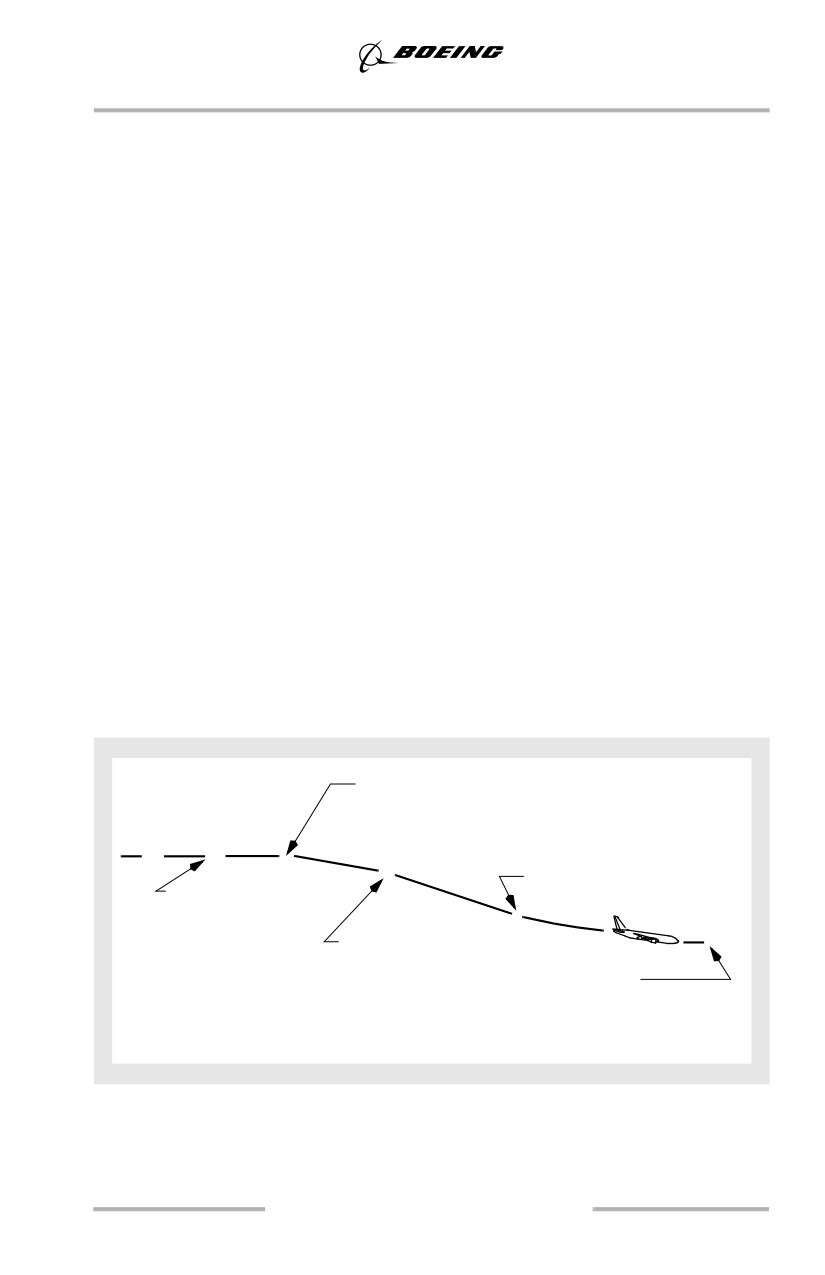
Performance of a non-normal checklist or sudden engine failure may lead to the
requirement to perform a single engine driftdown.
If an engine failure occurs while at cruise altitude, it may be necessary to descend.
The autothrottle should be disconnected and the thrust manually set to CON. On
the FMC CRZ page, select the ENG OUT prompt, followed by the prompt
corresponding to the failed engine. This displays MOD ENG OUT CRZ (ENG
OUT CRZ for FMC U10.3 and later) and the FMC calculates engine out target
speed and maximum engine out altitude at the current gross weight. The fields are
updated as fuel is burned.
Set the MAX altitude in the MCP altitude window and the engine out target
airspeed in the MCP IAS window. Allow airspeed to slow to engine out speed then
engage LVL CHG. If the engine out target airspeed and maximum continuous
thrust (MCT) are maintained, the airplane levels off above the original MAX
altitude. However, the updated MAX altitude is displayed on the ENG OUT CRZ
page. After viewing engine out data, select the ERASE prompt to return to the
active CRZ page. With the MOD ENG OUT CRZ page selected, no other FMC
data pages can be executed.
After level off at the target altitude, maintain MCT and allow the airplane to
accelerate to the single engine long range cruise speed. Maintain this speed with
manual thrust adjustments. Entering the new cruise altitude and airspeed on the
ECON CRZ page updates the ETAs and Top of Descent predictions. Refer to
Engine Out Familiarization, chapter 7, for trim techniques.
• Select ENG OUT CRZ
• Set engine out altitude and airspeed on MCP
Engine
• Slow to ENG OUT airspeed
failure
• Select LVL CHG
•
•
•
•
• Non-normal checklist
• Disconnect
autothrottle
•
• Select CON
• Notify ATC
•
thrust in FMC
• Initiate turn
• Manually set
• Maintain CON
with HDG SEL
limit thrust
(if required)
• Accelerate to single engine
long range cruise speed
• Determine course of action
Note: If the airplane is at or below maximum ENG OUT altitude when an engine
becomes inoperative, select the MOD ENG OUT CRZ (ENG OUT CRZ
for FMC U10.3 and later). Maintain engine out cruise speed using manual
thrust adjustments.
4.11
Climb, Cruise, Descent and
Holding
High Altitude High Speed Flight
The airplane exhibits excellent stability throughout the high altitude / high Mach
range. Mach buffet is not normally encountered at high Mach cruise. The airplane
does not have a Mach tuck tendency.
With Mach trim inoperative, the airplane exhibits a slight nose down trim change
when accelerating to speeds approaching MMO, however, control force changes
are light and easily managed. When the Mach trim system is operative, the nose
down trim change is nearly imperceptible except by referencing the control
column position.
As speed nears MMO, drag increases rapidly. At high weights, sufficient thrust
may not be available to accelerate to MMO in level flight at normal cruising
altitudes.
ETOPS
Extended Range Operation with Two Engine Airplanes (ETOPS) are those flights
which include points at a flying distance greater than one hour (in still air) single
engine cruise speed from an adequate airport. Improved technology and the
increased reliability of two engine airplanes has prompted a re-examination of the
rules governing their flights over oceans or desolate areas.
ETOPS Requirements and Approval
Operators conducting ETOPS are required to comply with the provisions of FAA
Advisory Circular 120-42A or other applicable governing regulations. An airline
must have an ETOPS configured airplane, and approved flight operations and
maintenance programs in place to support ETOPS operations.
The Minimum Equipment List (MEL) and the Dispatch Deviations Guide (DDG)
include dispatch relief levels appropriate to ETOPS.
The airline ensures that the ETOPS airplane is in compliance with the
requirements of the appropriate Boeing Configuration, Maintenance and
Procedures (CMP) documents. The airline's maintenance department must
develop programs which monitor and report reliability of the engines, airframe
and components. The Minimum Equipment List (MEL) and the Dispatch
Deviations Guide (DDG) have been expanded to address the improved
redundancy levels and the additional equipment unique to ETOPS configured
airplanes.
4.12
Climb, Cruise, Descent and
Holding
Flight and Performance
Crews undertaking ETOPS flights must be familiar with the suitable enroute
alternates listed in the flight plan. These airports must meet ETOPS weather
minima which require an incremental increase above conventional alternate
minimums, and be located so as to ensure that the airplane can divert and land in
the event of a system failure requiring a diversion.
Planning an ETOPS flight requires an understanding of the area of operations,
critical fuel reserves, altitude capability, cruise performance tables and icing
penalties. The Flight Planning and Performance Manual (FPPM) provides
guidance to compute critical fuel reserves which are essential for the flight crew
to satisfy the requirements of the ETOPS flight profile. The FPPM also provides
single engine altitude capability and cruise and diversion fuel information at
ETOPS planning speeds. This information is not included in the FCOM/QRH.
Fuel reserve corrections must be made for winds, non-standard atmospheric
conditions, performance deterioration caused by engines or airframe, and when
needed, flight through forecast icing conditions.
Note: Critical fuel calculations are part of the ETOPS dispatch process and are
not normally calculated by the flight crew. The crew normally receives
ETOPS critical fuel information in the Computer Flight Plan (CFP).
Procedures
Normal procedures on ETOPS flights do not differ from standard normal
procedures. However, during the last hour of ETOPS cruise, the FAA currently
requires that a fuel crossfeed valve check be performed on airplanes with a single
crossfeed valve. This verifies that the crossfeed valve is operating so that on the
subsequent flight, if an engine fails, fuel feed is available from both main tanks
through the crossfeed valve.
Before entering the ETOPS phase of flight, the APU must be operating.
ETOPS engine-out procedures may be different from standard non-normal
procedures. Following an engine failure the crew performs a modified
“driftdown” procedure determined by the ETOPS route requirements. This
procedure typically uses higher descent and cruise speeds, and a lower cruise
altitude following engine failure. This allows the airplane to reach an alternate
airport within the specific time limits authorized for the operator. These cruise
speeds and altitudes are determined by the airline and approved by its regulatory
agency and usually differ from the engine-out speeds provided by the FMC. The
captain, however, has the discretion to modify this speed if actual conditions
following the diversion decision dictate such a change.
4.13
Climb, Cruise, Descent and
Holding
Polar Operations
Refer to the FMC Polar Navigation section in Volume 2 of the FCOM for specifics
about operations in polar regions and a description of the boundaries of the polar
regions.
During preflight planning extremely cold air masses should be noted and cold fuel
temperatures should be considered. See the Low Fuel Temperature section in this
chapter for details regarding recommendations and crew actions.
Operators should establish a remote airport diversion plan to include supporting
the airplane, passengers and crew. Airplane equipment and document needs to be
considered:
• cold weather clothing to enable one or more crewmembers to exit the
airplane at a diversion airport with extreme cold conditions
• comprehensive instructions on securing the airplane for cold weather to
include draining water tanks, etc.
• diversion airport data to include airport diagrams, information on nearby
terrain and photographs (if available), emergency equipment availability,
etc.
• cold temperature altitude correction table.
Due to limited availability of alternate airports relative to other regions, special
attention should be given to diversion planning including airport conditions and
availability of compatible fuel. Crews should be prepared to operate in QFE and
metric altitude where required. Expect changes in assigned cruising levels enroute
since standard cruising levels vary by FIR. Some airports provide QNH upon
request, even if their standard is QFE. Metric wind speed (m/sec) may be all that
is available. A simple approximation: 1 m/sec = 2 knots. A feet to meters
conversion chart may be useful for planning step climbs, converting minima, etc.
Use caution when using ADF and/or VOR raw data. ADF orientation (true or
magnetic) is determined by the heading reference selected by the crew. VOR
radials are displayed according to the orientation of the VOR station.
Communications should be handled according to the applicable enroute charts.
Above 82 degrees N, SATCOM is unavailable. HF frequencies and HF SELCAL
must be arranged by the flight crew prior to the end of SATCOM coverage.
Routine company communications procedures should include flight following to
enable immediate assistance during a diversion or other emergency.
Note: To use SATCOM on the ground, the IRUs must be aligned.
4.14
Climb, Cruise, Descent and
Holding
When navigating in the polar regions, magnetic heading should be considered
unreliable or totally useless for navigation. Magnetic variations typically are
extreme, often are not constant at the same point and change rapidly as airplane
position changes. Ensure the computer flight plan shows true tracks and true
headings. Grid headings may also be used as a reference for those airplanes
equipped with grid heading indicators although no airplane systems use grid
heading. For some high latitude airports, grid headings are shown on the
instrument approach procedures. Note that unmapped areas in the GPWS terrain
data base display as magenta dots on the map, regardless of the airplane altitude.
The primary roll mode for polar operations should be LNAV, which may be used
with the heading reference switch in the NORM position. HDG SEL/HOLD are
functional but require the manual selection of TRUE heading reference.
Deviations from planned route may be accomplished in HDG SEL.
Note: Do not use HDG SEL or ROLL CWS north of 89 degrees 30 minutes North
latitude or south of 89 degrees 30 minutes South latitude, due to rapid
heading and track changes occurring near either pole. At latitudes north of
N85 or south of S85, the true heading on the RMI may differ from the True
Heading displayed on the MAP(s), due to position differences between
IRU-L and FMC.
Loss of both GPS units results in an increased ANP and possible display of the
UNABLE REQD NAV PERF-RNP message but normally does not prevent
continuing the polar flight.
If neither IRU is operating in the NAV mode, the airplane heading/track on the
PFD and map is invalid. The GPS-L True Track on CDU PROGRESS 3/3 page
provides a source of airplane track, which can be used as a secondary reference to
update the heading for any IRS in ATT mode.
4.15
Climb, Cruise, Descent and
Holding
Descent
Descent Speed Determination
The default FMC descent speed schedule is an economy (ECON) descent from
cruise altitude to the airport speed transition altitude followed by a descent at ten
knots less than this speed. The speed schedule is adjusted to accommodate
waypoint speed/altitude constraints displayed on the LEGS pages, and
speed/altitude constraints displayed on the DES page. If desired, the ECON speed
schedule can be modified by alternate Mach, Mach/IAS, or IAS values on the DES
page target speed line. If the FMC information is not available, use target speeds
from the Descent Rates table in this chapter.
Descent Path
An FMC path descent is the most economical descent method. At least one
waypoint-related altitude constraint below cruise altitude on a LEGS page
generates a descent guidance path. The path is built from the lowest constraint
upward, assuming idle thrust, or approach idle below the anti-ice altitude entered
on the DESCENT FORECAST page.
The path is based on the descent speed schedule, any entered speed/altitude
constraints or forecast use of anti-ice. The path reflects descent wind values
entered on the DESCENT FORECAST page.
Descent Constraints
Descent constraints may be automatically entered in the route when selecting an
arrival procedure, or manually entered through the CDU.
Set all mandatory altitude restrictions and “at or above” constraints in the Mode
Control Panel (MCP) altitude window. The next altitude may be set when the
restriction has been assured or further clearance has been received.
Shallow vertical path segments may result in the autothrottle supplying partial
power to maintain the target speed. Vertical path segments steeper than an idle
descent may require the use of speedbrakes for speed control. Deceleration
requirements below cruise altitude (such as at 10,000 MSL) are accomplished
based on a rate of descent of approximately 500 fpm. When a deceleration is
required at top of descent, it is performed in level flight.
Speed Intervention (As installed)
VNAV speed intervention can be used to respond to ATC speed change
requirements. VNAV SPD pitch mode responds to speed intervention by changing
airplane pitch while the thrust remains at idle. VNAV PTH pitch mode may require
the use of speedbrakes or increased thrust to maintain the desired airspeed.
4.16
Climb, Cruise, Descent and
Holding
Descent Preparation Using HUD System
If the combiner was previously stowed, the combiner should be positioned and the
pilot should verify that it is properly aligned with the overhead unit. For night
landings, set combiner brightness high enough to ensure that the symbology is
visible over bright touchdown zone lights.
Descent Planning
Flight deck workload typically increases as the airplane descends into the terminal
area. Distractions must be minimized and administrative and nonessential duties
completed before descent or postponed until after landing. Perform essential
duties early in the descent so more time is available during the critical approach
and landing phases.
Operational factors and/or terminal area requirements may not allow following
the optimum descent schedule. Terminal area requirements can be incorporated
into basic flight planning but ATC, weather, icing and other traffic may require
adjustments to the planned descent schedule.
Proper descent planning is necessary to arrive at the desired altitude at the proper
speed and configuration. The distance required for the descent is approximately 3
NM/1000 feet altitude loss for no wind conditions using ECON speed. Rate of
descent is dependent upon thrust, drag, airspeed schedule and gross weight.
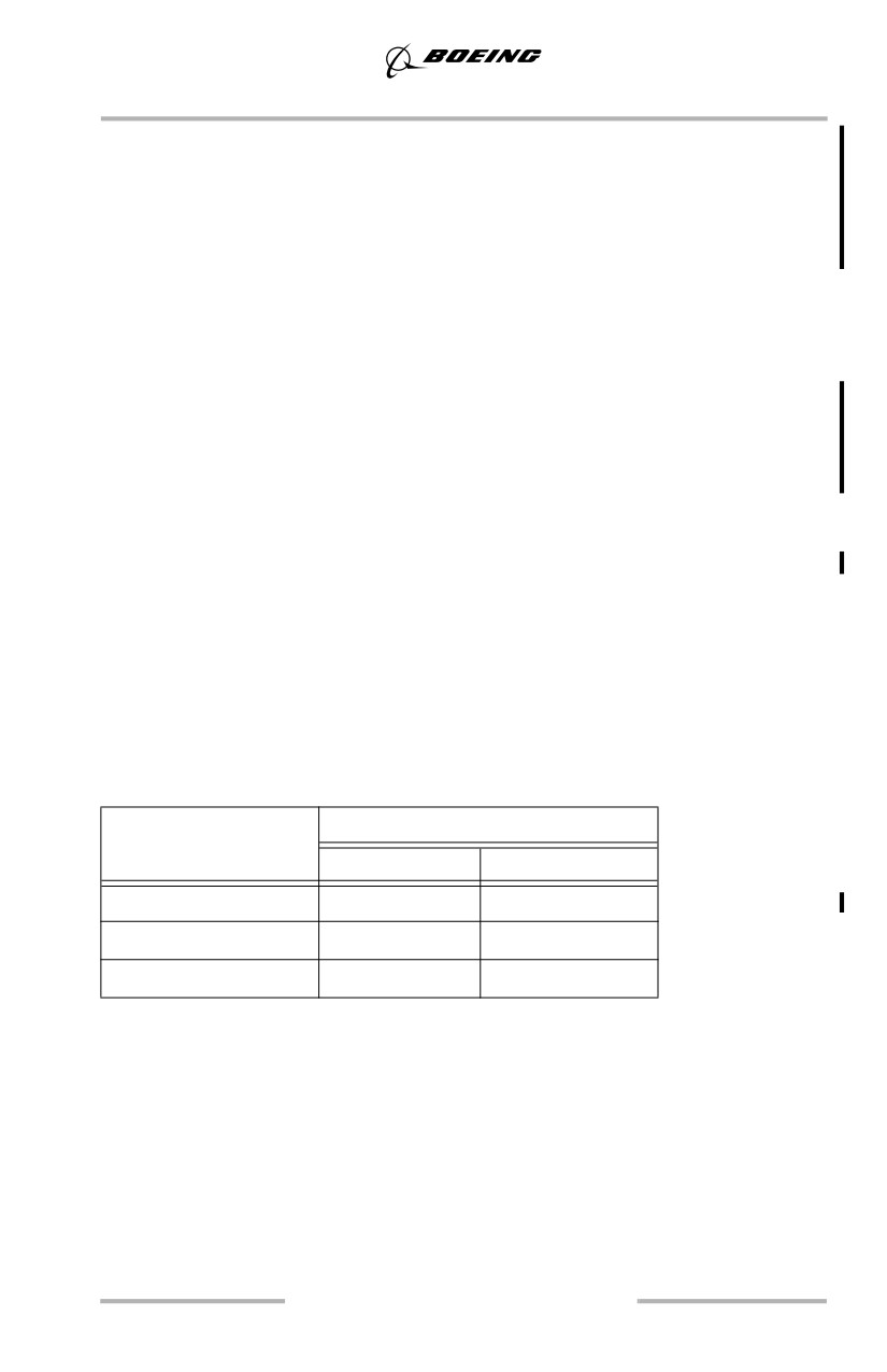
Descent Rates
Descent Rate tables provide typical rates of descent below 20,000 feet with idle
thrust and speedbrakes extended or retracted.
Rate of Descent (Typical)
Target Speed
Clean
With Speedbrake
0.78M / 280 knots
2200 fpm
3100 fpm
250 knots
1700 fpm
2300 fpm
VREF 40 + 70
1100 fpm
1400 fpm
Normally, descend with idle thrust and in clean configuration (no speedbrakes).
Maintain cruise altitude until the proper distance or time out for the planned
descent and then hold the selected airspeed schedule during descent. Deviations
from this schedule may result in arriving too high at destination and require
circling to descend, or arriving too low and far out requiring extra time and fuel to
reach destination.
The speedbrake may be used to correct the descent profile if arriving too high or
too fast. The Descent Procedure is normally initiated before the airplane descends
below the cruise altitude for arrival at destination, and should be completed by
10,000 feet MSL. The Approach Procedure is normally started at transition level.
4.17
Climb, Cruise, Descent and
Holding
Plan the descent to arrive at traffic pattern altitude at flaps up maneuvering speed
approximately 12 miles from the runway when proceeding straight-in or about 8
miles out when making an abeam approach. A good crosscheck is to be at 10,000
feet AGL, 30 miles from the airport, at 250 knots.
Losing airspeed can be difficult and may require a level flight segment. For
planning purposes, it requires approximately 25 seconds and 2 NM to decelerate
from 280 to 250 knots in level flight without speedbrakes. It requires an additional
35 seconds and 3 NM to decelerate to flaps up maneuvering speed at average gross
weights. Using speedbrakes to aid in deceleration reduces these times and
distances by approximately 50%.
Maintaining the desired descent profile and using the map mode to maintain
awareness of position ensures a more efficient operation. Maintain awareness of
the destination weather and traffic conditions, and consider the requirements of a
potential diversion. Review the airport approach charts and discuss the plan for the
approach, landing, and taxi routing to parking. Complete the approach briefing as
soon as practical, preferably before arriving at top of descent. This allows full
attention to be given to airplane control.
Speedbrakes
The PF should keep a hand on the speedbrake lever when the speedbrakes are used
in-flight. This helps prevent leaving the speedbrake extended when no longer
required.
Use of speedbrakes between the down detent and flight detent can result in rapid
roll rates and normally should be avoided. While using the speedbrakes in descent,
allow sufficient altitude and airspeed margin to level off smoothly. Lower the
speedbrakes before adding thrust.
Note: In flight, do not extend the speedbrake lever beyond the FLIGHT detent.
The use of speedbrakes with flaps extended should be avoided, if possible. With
flaps 15 or greater, the speedbrakes should be retracted. If circumstances dictate
the use of speedbrakes with flaps extended, high sink rates during the approach
should be avoided. Speedbrakes should be retracted before reaching 1,000 feet
AGL.
The flaps are normally not used for increasing the descent rate. Normal descents
are made in the clean configuration to pattern or instrument approach altitude.
When descending with the autopilot engaged and the speedbrakes extended at
speeds near VMO/MMO, the airspeed may momentarily increase to above
VMO/MMO if the speedbrakes are retracted quickly. To avoid this condition,
smoothly and slowly retract the speedbrakes to allow the autopilot sufficient time
to adjust the pitch attitude to maintain the airspeed within limits.
4.18
Climb, Cruise, Descent and
Holding
When the speedbrakes are retracted during altitude capture near VMO/MMO, a
momentary overspeed condition may occur. This is because the autopilot captures
the selected altitude smoothly by maintaining a fixed path while the thrust is at or
near idle. To avoid this condition, it may be necessary to reduce the selected speed
and/or descent rate prior to altitude capture or reduce the selected speed and delay
speedbrake retraction until after level off is complete.
Flaps and Landing Gear
Normal descents are made in the clean configuration to pattern or instrument
approach altitude. If greater descent rates are desired, extend the speedbrakes.
When thrust requirements for anti-icing result in less than normal descent rates
with speedbrakes extended, or if higher than normal descent rates are required by
ATC clearance, the landing gear can be lowered to increase the rate of descent.
Extend the flaps when in the terminal area and conditions require a reduction in
airspeed below flaps up maneuvering speed. Normally select flaps 5 prior to the
approach fix going outbound, or just before entering downwind on a visual
approach.
Note: Avoid using the landing gear for increased drag. This minimizes passenger
discomfort and increases gear door life.
Speed Restrictions
Speed restrictions below specific altitudes/flight levels and in the vicinity of
airports are common. At high gross weights, minimum maneuvering speed may
exceed these limits. Consider extending the flaps to attain a lower maneuvering
speed or obtain clearance for a higher airspeed from ATC.
Other speeds may be assigned by ATC. Pilots complying with speed adjustments
are expected to maintain the speed within plus or minus 10 knots.
Engine Icing During Descent
The use of anti-ice and the increased thrust required increases the descent
distance. Therefore, proper descent planning is necessary to arrive at the initial
approach fix at the correct altitude, speed, and configuration. The anticipated
anti-ice use altitude should be entered on the DESCENT FORECAST page to
assist the FMC in computing a more accurate descent profile.
4.19
Climb, Cruise, Descent and
Holding
Engine icing may form when not expected and may occur when there is no
evidence of icing on the windshield or other parts of the airplane. Once ice starts
to form, accumulation can build very rapidly. Although one bank of clouds may
not cause icing, another bank, which is similar, may induce icing.
Note: The engine anti-icing system should be turned on whenever icing
conditions exist or are anticipated. Failure to follow the recommended
anti-ice procedures can result in engine stall, overtemperature or engine
damage.
Holding
Start reducing to holding airspeed 3 minutes before arrival time at the holding fix
so that the airplane crosses the fix, initially, at or below the maximum holding
airspeed.
If the FMC holding speed is greater than the ICAO or FAA maximum holding
speed, holding may be conducted at flaps 1, using flaps 1 maneuvering speed.
Flaps 1 uses approximately 10% more fuel than flaps up. Holding speeds in the
FMC provide an optimum holding speed based upon fuel burn and speed
capability; but are never lower than flaps up maneuvering speed.
If holding speed is not available from the FMC, refer to the PI section of the QRH.
Recommended holding speeds can be approximated by using the following
guidance until more accurate speeds are obtained from the QRH:
• flaps up maneuvering speed approximates minimum fuel burn speed and
may be used at low altitudes
• above FL250, use VREF 40 + 100 knots to provide adequate buffet
margin.
Procedure Holding
When a procedure holding pattern is selected from the navigation data base and
the FMC shows PROC HOLD on the legs page, the following is true when the
PROC HOLD is the active leg:
• exiting the holding pattern is automatic; there is no need to select EXIT
HOLD
• if the crew desires to remain in holding a new holding pattern must be
entered.
4.20

Climb, Cruise, Descent and
Holding
ICAO Holding Airspeeds (Maximum)
Altitude
Speed
Through 14,000 feet
230 knots
Above 14,000 to 20,000 feet MSL
240 knots
Above 20,000 to 34,000 feet MSL
265 knots
Above 34,000 feet MSL
0.83M
FAA Holding Airspeeds (Maximum)
Altitude
Speed
Through 6,000 feet MSL
200 knots
6,001 feet MSL through
230 knots
14,000 feet MSL
(210 knots Washington D. C. & New York FIRs)
14,001 feet MSL and above
265 knots
Maintain clean configuration if holding in icing conditions or in turbulence.
If the holding pattern has not been programmed in the FMC, the initial outbound
leg should be flown for 1 minute or 1 1/2 minutes as required by altitude. Timing
for subsequent outbound legs should be adjusted as necessary to achieve proper
inbound leg timing.
In extreme wind conditions or at high holding speeds, the defined holding pattern
protected airspace may be exceeded. However, the holding pattern depicted on the
map display will not exceed the limits. Advise ATC if an increase in airspeed is
necessary due to turbulence, if unable to accomplish any part of the holding
procedure, or if unable to comply with speeds listed in the tables above.
4.21
Climb, Cruise, Descent and
Holding
Intentionally
Blank
4.22
Approach and Missed Approach
Chapter 5
Table of Contents
Section TOC
5.TOC Approach and Missed Approach-Table of Contents
Preface
5.1
Approach
5.1
Instrument Approaches
5.1
Approach Briefing
5.2
Approach Category
5.2
Approach Clearance
5.3
Procedure Turn
5.4
Stabilized Approach Recommendations
5.4
Mandatory Missed Approach
5.5
Landing Minima
5.6
Radio Altimeter (RA)
5.6
Missed Approach Point (MAP)
5.6
Determination of a MAP
5.7
Instrument Landing System (ILS)
5.7
Instrument Approach using VNAV or IAN (As installed)
5.7
Localizer
5.7
Other Non-ILS Approaches
5.8
Precision Approach Radar (PAR)
5.8
Airport Surveillance Radar (ASR)
5.8
ILS Approach
5.9
ILS Approach - Fail Passive
5.9
ILS Approach - Fail Operational
5.10
ILS Approach - General
5.11
Decision Altitude/Height - DA(H)
5.11
Alert Height - AH
5.11
Fail Operational
5.11
5.TOC.1
Approach and Missed Approach -
Table of Contents
Fail Passive
5.11
Procedure Turn and Initial Approach
5.12
Approach
5.12
Decision Altitude/Height - DA(H)
5.15
Raw Data - (No Flight Director)
5.15
AFDS Autoland Capabilities
5.16
Low Visibility Approaches
5.18
AFDS Faults
5.21
ILS Approach/Landing Geometry
5.24
Non-Normal Operations
5.25
Non - ILS Instrument Approaches
5.29
Non - ILS Instrument Approaches - General
5.29
Procedure Turn and Initial Approach
5.37
Vertical Path Construction
5.37
Instrument Approach Using VNAV
5.40
Instrument Approach Using IAN (As installed)
5.45
Instrument Approach Using V/S
5.50
Visual Descent Point
5.53
Missed Approach - Non-ILS
5.54
Circling Approach
5.55
Circling Approach - General
5.56
Obstruction Clearance
5.56
Circling Approach - One Engine Inoperative
5.57
Missed Approach - Circling
5.57
Visual Traffic Pattern
5.59
Visual Approach - General
5.60
Thrust
5.60
Downwind and Base Leg
5.60
Final Approach
5.61
5.TOC.2
Approach and Missed Approach -
Table of Contents
Engine Failure On Final Approach
5.61
Touch and Go Landings
5.62
Touch and Go Landing - General
5.63
Approach
5.63
Landing
5.63
Stop and Go Landings
5.63
Go-Around and Missed Approach - All Approaches
5.65
Go-Around and Missed Approach - All Engines Operating
5.66
Go-Around after Touchdown
5.67
Go-Around and Missed Approach - One Engine Inoperative
5.68
Engine Failure During Go-Around and Missed Approach
5.68
5.TOC.3
Approach and Missed Approach -
Table of Contents
Intentionally
Blank
5.TOC.4
Approach and Missed Approach
Chapter 5
Preface
This chapter outlines recommended operating practices and techniques for ILS,
non-ILS, circling and visual approaches, and the Go-Around and Missed
Approach maneuver. Flight profile illustrations represent the recommended basic
configuration for normal and non-normal flight maneuvers and provide a basis for
standardization and crew coordination.
The maneuvers are normally accomplished as illustrated. However, due to
conflicting traffic at training airports, air traffic separation requirements, and radar
vectors, modifications may be necessary. Conditions beyond the control of the
flight crew may preclude following an illustrated maneuver exactly. The
maneuver profiles are not intended to replace good judgment and logic.
Approach
Instrument Approaches
All safe instrument approaches have certain basic factors in common. These
include good descent planning, careful review of the approach procedure, accurate
flying, and good crew coordination. Thorough planning is the key to a safe,
unhurried, professional approach.
Ensure the waypoint sequence on the LEGS page, altitude restrictions, and the
map display reflect the air traffic clearance. Last minute air traffic changes or
constraints may be managed by appropriate use of the MCP heading and altitude
selectors. Updating the waypoint sequence on the LEGS page should be
accomplished only as time permits.
Complete the approach preparations before arrival in the terminal area. Set
decision altitude/height DA(H) or minimum descent altitude/height MDA(H).
Crosscheck radio and pressure altimeters whenever practical. Do not completely
abandon enroute navigation procedures even though air traffic is providing radar
vectors to the initial or final approach fix. Check ADF/VOR selector set to the
proper position. Verify ILS, VOR and ADF are tuned and identified if required for
the approach.
Note: The requirement to tune and identify navaids can be satisfied by
confirming that the tuned navaid frequency is replaced by the correct
alphabetical identifier on the PFD/ND (as installed) or by aurally
identifying the navaid.
5.1

Approach and Missed Approach
Check that the marker beacon is selected on the audio panel. The course and glide
slope signals are reliable only when their warning flags are not displayed, localizer
and glide slope pointers are in view, and the ILS identifier is received. Confirm the
published approach inbound course is set or displayed.
Do not use radio navigation aid facilities that are out of service even though flight
deck indications appear normal. Radio navigation aids that are out of service may
have erroneous transmissions that are not detected by airplane receivers and no
flight deck warning is provided to the crew.
Approach Briefing
Before the start of an instrument approach, the PF should brief the PM of his
intentions in conducting the approach. Both pilots should review the approach
procedure. All pertinent approach information, including minimums and missed
approach procedures, should be reviewed and alternate courses of action
considered.
As a guide, the approach briefing should include at least the following:
• weather and NOTAMS at destination and alternate, as applicable
• type of approach and the validity of the charts to be used
• navigation and communication frequencies to be used
• minimum safe sector altitudes for that airport
• approach procedure including courses and heading
• vertical profile including all minimum altitudes, crossing altitudes and
approach minimums
• determination of the Missed Approach Point (MAP) and the missed
approach procedure
• other related crew actions such as tuning of radios, setting of course
information, or other special requirements
• taxi routing to parking
• any appropriate information related to a non-normal procedure
• management of AFDS.
Approach Category
FAA Category
Speed
C
121 knots or more but less than 141 knots
D
141 knots or more but less than 166 knots
Speed - based upon a speed of VREF in the landing configuration at
maximum certificated landing weight.
5.2

Approach and Missed Approach
Range of
Range of
Range of
Max Speeds
Max Speeds for
ICAO
Speeds at
Speeds for
Speeds for
for Visual
Missed Approach
Category
Threshold
Initial
Final
Maneuvering
Inter-
Final
Approach
Approach
(Circling)
mediate
C
121/140
160/240
115/160
180
160
240
D
141/165
185/250
130/185
205
185
265
Speeds at threshold - based upon a speed of VREF in the landing configuration at
maximum certified landing weight.
The designated approach category for an aircraft type is defined by the landing
reference speed (VREF) at the maximum certified landing weight under both USA
TERPS and ICAO PANS OPS.
• The 737 is classified as a Category “C” airplane for straight in
approaches.
For circling approaches, the anticipated circling speed at the actual weight is used
to determine the required approach minimums. This is because circling approach
minimums for both USA TERPS and ICAO PANS OPS are based on obstruction
clearance for approach maneuvering within a defined region of airspace. The
region of airspace is determined as a function of actual airplane speed. This region
gets larger with increasing speed, which may result in higher approach minimums
depending on the terrain characteristics surrounding the airport. Similarly,
approach minimums may decrease as speed is reduced for the same reason.
However, the use of lower circling approach minimums based on actual approach
speeds does not change the designated approach category of the airplane. Circling
approach minimums are normally published as a function of maximum airplane
speeds for circling in lieu of airplane approach categories on Jeppesen Approach
Charts.
Approach Clearance
When cleared for an approach and on a published segment of that approach, the
pilot is authorized to descend to the minimum altitude for that segment. When
cleared for an approach and not on a published segment of the approach, maintain
assigned altitude until crossing the initial approach fix or established on a
published segment of that approach. If established in a holding pattern at the final
approach fix, the pilot is authorized to descend to the procedure turn altitude when
cleared for the approach.
If using a VNAV path, all altitude and speed constraints must be entered either
manually, by selecting a published arrival, or by a combination of both. When
properly entered, the VNAV path profile complies with all altitude constraints.
Crossing altitudes may be higher than the minimum altitudes for that segment
because the VNAV path is designed to optimize descent profiles.
5.3
Approach and Missed Approach
When conducting an instrument approach from the holding pattern, continue on
the same pattern as holding, extend flaps to 5 on the outbound track parallel to
final approach course. Turn inbound on the procedure turn heading. This type of
approach is also referred to as a race track approach.
Procedure Turn
On most approaches the procedure turn must be completed within specified limits,
such as within 10 NM of the procedure turn fix or beacon. The FMC depicted
procedure turn, or holding pattern in lieu of procedure turn, complies with airspace
limits. The published procedure turn altitudes are normally minimum altitudes.
The FMC constructs the procedure turn path based upon predicted winds, a 170
knot airspeed and the “excursion” distance in the nav database for the procedure.
Adjust time outbound for airspeed, wind effects, and location of the procedure
turn fix. If the procedure turn fix is crossed at an excessively high ground speed,
the procedure turn protected airspace may be exceeded. The procedure turn should
be monitored using the map to assure the airplane remains within protected
airspace.
Stabilized Approach Recommendations
Maintaining a stable speed, descent rate, and vertical/lateral flight path in landing
configuration is commonly referred to as the stabilized approach concept.
Any significant deviation from planned flight path, airspeed, or descent rate
should be announced. The decision to execute a go-around is no indication of poor
performance.
Note: Do not attempt to land from an unstable approach.
Recommended Elements of a Stabilized Approach
The following recommendations are consistent with criteria developed by the
Flight Safety Foundation.
All approaches should be stabilized by 1,000 feet above airport elevation in
instrument meteorological conditions (IMC) and by 500 feet above airport
elevation in visual meteorological conditions (VMC). An approach is considered
stabilized when all of the following criteria are met:
• the airplane is on the correct flight path
• only small changes in heading/pitch are required to maintain the correct
flight path
• the airplane speed is not more than VREF + 20 knots indicated airspeed
and not less than VREF
• the airplane is in the correct landing configuration
• sink rate is no greater than 1,000 fpm; if an approach requires a sink rate
greater than 1,000 fpm, a special briefing should be conducted
5.4
Approach and Missed Approach
• power setting is appropriate for the airplane configuration
• all briefings and checklists have been conducted.
Specific types of approaches are stabilized if they also fulfill the following:
• ILS approaches should be flown within one dot of the glide slope and
localizer, or within the expanded localizer scale
• during a circling approach, wings should be level on final when the
airplane reaches 300 feet above airport elevation.
Unique approach procedures or abnormal conditions requiring a deviation from
the above elements of a stabilized approach require a special briefing.
Note: An approach that becomes unstabilized below 1,000 feet above airport
elevation in IMC or below 500 feet above airport elevation in VMC
requires an immediate go-around.
These conditions should be maintained throughout the rest of the approach for it
to be considered a stabilized approach. If the above criteria cannot be established
and maintained at and below 500 feet AFE, initiate a go-around.
At 100 feet HAT for all visual approaches, the airplane should be positioned so the
flight deck is within, and tracking to remain within, the lateral confines of the
runway edges extended.
As the airplane crosses the runway threshold it should be:
• stabilized on target airspeed to within + 10 knots until arresting descent
rate at flare
• on a stabilized flight path using normal maneuvering
• positioned to make a normal landing in the touchdown zone (the first
3,000 feet or first third of the runway, whichever is less).
Initiate a go-around if the above criteria cannot be maintained.
Maneuvering (including runway changes and circling)
When maneuvering below 500 feet, be cautious of the following:
• descent rate change to acquire glide path
• lateral displacement from the runway centerline
• tailwind/crosswind components
• runway length available.
Mandatory Missed Approach
On all instrument approaches, where suitable visual reference has not been
established and maintained, execute an immediate missed approach when:
• a navigation radio or flight instrument failure occurs which affects the
ability to safely complete the approach
• the navigation instruments show significant disagreement
5.5
Approach and Missed Approach
• on ILS final approach and either the localizer or the glide slope indicator
shows full deflection
• on an RNP based approach and an alert message indicates that ANP
exceeds RNP
• on an RNP based approach using a level of RNP which requires NPS and
either the lateral or vertical deviation NPS pointer cannot be maintained
within the ANP limits
• on a radar approach and radio communication is lost.
Landing Minima
Most regulatory agencies require visibility for landing minima. Ceilings are not
required. There are limits on how far an airplane can descend without visual
contact with the runway environment when making an approach. Descent limits
are based on a decision altitude/height DA(H) for approaches using a glide slope
or certain approaches using a VNAV path; or a MDA(H) for approaches that do
not use vertical guidance, or where a DA(H) is not authorized for use. Most
agencies do not require specific visual references below alert height (AH).
Approach charts use the abbreviation DA(H) or MDA(H). DA(H) applies to
Category I, II, and certain fail passive Category III operations. A decision altitude
“DA” or minimum descent altitude “MDA” is referenced to MSL and the
parenthetical height “(H)” is referenced to Touchdown Zone Elevation (TDZE) or
threshold elevation. Example: A DA(H) of 1,440’ (200’) is a DA of 1,440’ with a
corresponding height above the touchdown zone of 200’.
When RVR is reported for the landing runway, it typically is used in lieu of the
reported meteorological visibility.
Radio Altimeter (RA)
A radio altimeter is normally used to determine DH when a DA(H) is specified for
Category II or Category III approaches, or to determine alert height (AH) for
Category III approaches. Procedures at airports with irregular terrain may use a
marker beacon instead of a DH to determine the missed approach point. The radio
altimeter may also be used to cross check the primary altimeter over known terrain
in the terminal area. However, unless specifically authorized, the radio altimeter
is not used for determining MDA(H) on instrument approaches. It should also not
be used for approaches where use of the radio altimeter is not authorized (RA
NOT AUTHORIZED). However, if the radio altimeter is used as a safety backup,
it should be discussed in the approach briefing.
Missed Approach Point (MAP)
A missed approach point is a point where a missed approach must be initiated if
suitable visual references are not available to make a safe landing or the airplane
is not in a position to make a safe landing.
5.6
Approach and Missed Approach
Determination of a MAP
For approaches such as ILS or GLS, the DA(H) in conjunction with the glide slope
is used to determine the MAP. For non-ILS or G/S out approaches, two methods
for determining the MAP are acceptable in lieu of timing due to the accuracy of
FMC positioning:
• when arriving at the MDA(H) or DA(H) in conjunction with a VNAV
path
• if not using a VNAV path, use of the map display to determine when the
airplane has reached the VDP or the MAP. The approach legs along with
distance and time to the missed approach waypoint are displayed on the
map.
Timing During Approaches
Since FMC use is appropriate for instrument approach navigation, timing is not
the primary means to determine the missed approach point. The probability of
multiple failures that would result in timing being the only method of determining
the missed approach point is remote. However, some regulatory agencies may still
require the use of timing for approaches. The timing table, when included, shows
the distance from the final approach fix to the MAP.
Timing for instrument approaches is not necessary as long as there is no unable
RNP alert displayed.
Instrument Landing System (ILS)
Arrival at the MAP is determined by reference to an altimeter. DA is determined
by reference to the barometric altimeter, while DH is determined by reference to
the radio altimeter.
Instrument Approach using VNAV or IAN (As installed)
When specifically authorized by the instrument procedure and regulatory
authority, approaches may be flown to the following minima:
• a published VNAV DA(H)
• a published MDA(H) used as a decision altitude.
When either of the above minima are not specifically approved, use the published
MDA(H) + 50 feet as the MAP.
Localizer
For most localizer approaches, the published MAP is the threshold of the runway.
However, if a localizer approach is flown in VNAV PTH, use the missed approach
criteria described in the Instrument Approach using VNAV or IAN (as installed)
section in this chapter.
5.7