Boeing 737 - 600/700/800/900. Flight Crew Training Manual (1999 year) - page 3
Ground Operations
If nose wheel “scrubbing” occurs while turning, reduce steering angle and/or taxi
speed. Avoid stopping the airplane in a turn as excessive thrust is required to start
taxiing again.
Differential thrust may be required at high weights during tight turns. This should
only be used as required to maintain the desired speed in the turn. After
completing a turn, center the nose wheels and allow the airplane to roll straight
ahead. This relieves stresses in the main and nose gear structure prior to stopping.
Turning Radius and Gear Tracking
During all turning maneuvers, crews should be aware of their position relative to
the nose and main landing gear. The pilot seat position being forward of the nose
wheels and main gear is depicted in the tables in this chapter.
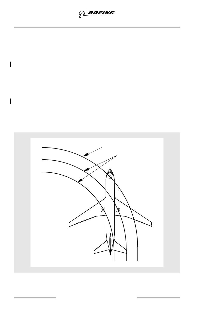
As the following diagram illustrates, while the airplane is turning, the main gear
tracks inside the nose gear. The smaller the radius of the turn, the greater the
distance that the main gear tracks inside the nose gear and the greater the need to
steer the nose gear outside of the taxi path (oversteer).
Nose gear track
Main gear tracks
(near centerline)
2.6
Ground Operations
Visual Cues and Techniques for Turning while Taxiing
The following visual cues assume the pilot’s seat is adjusted for proper eye
position. The following techniques also assume a typical taxiway width. Since
there are many combinations of turn angles, taxiway widths, fillet sizes and
taxiway surface conditions, pilot judgment must dictate the point of turn initiation
and the amount of nose wheel steering wheel required for each turn. Except for
turns less than approximately 30°, speed should be 10 knots or less prior to turn
entry. For all turns, keep in mind the main gear are located behind the nose wheels,
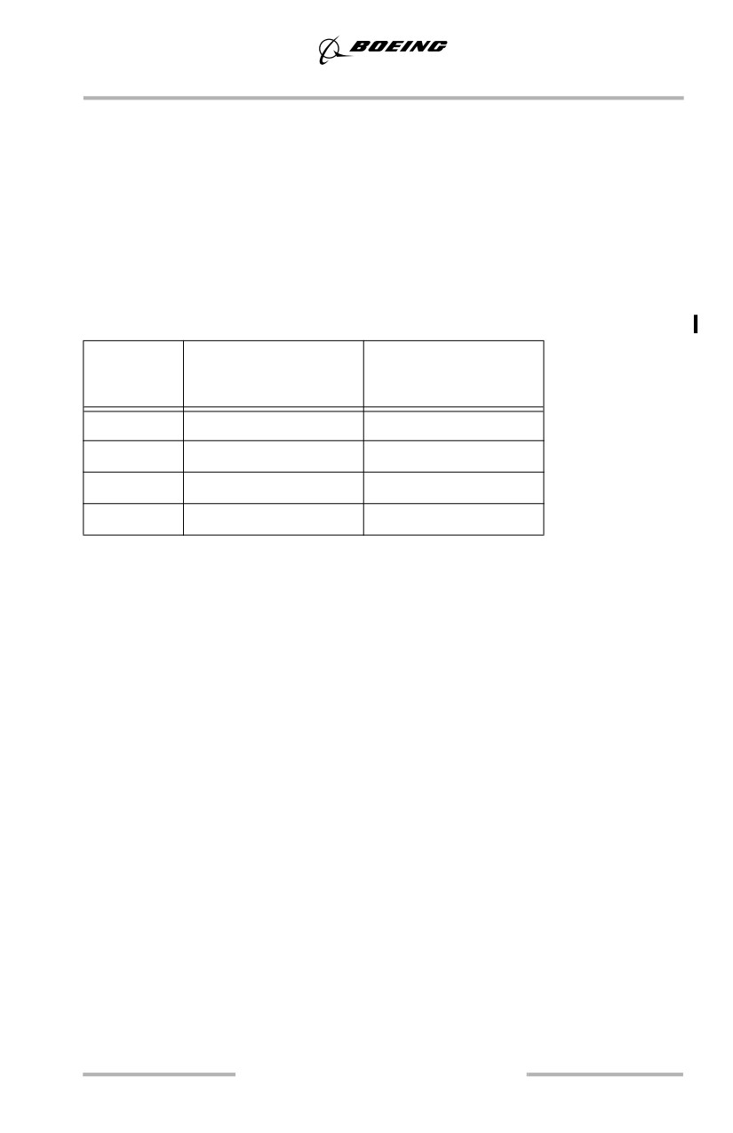
which causes them to track inside the nose wheels during turns. The pilot position
being forward of the nose wheels and main gear is depicted in the table below.
Model
Pilot Seat Position
Pilot Seat Position
(forward of nose gear)
(forward of main gear
feet (meters)
feet (meters))
737 - 600
5.25
(1.6)
42 (12.8)
737 - 700
5.25
(1.6)
47 (14.3)
737 - 800
5.25
(1.6)
56 (17.1)
737 - 900
5.25
(1.6)
62 (18.9)
Turns less than 90 degrees
Use a technique similar to other large airplanes: steer the nose wheels far enough
beyond the centerline of the turn to keep the main gear close to the centerline.
Turns of 90 degrees or more
Initiate the turn as the intersecting taxiway centerline (or intended exit point)
approaches approximately the center of the number 3 window. Initially use
approximately full nose wheel steering wheel displacement. Adjust the steering
wheel input as the airplane turns to keep the nose wheels outside of the taxiway
centerline, near the outside radius of the turn. Nearing turn completion, when the
main gear are clear of the inside radius, gradually release the steering wheel input
as the airplane lines up with the intersecting taxiway centerline or intended taxi
path.
Turns of 180 Degrees
If the available taxi surface is narrow, coordination with ATC and ground support
personnel may be required to complete the operation safely. Reference special
aerodrome operating instructions, if available. In some cases (e.g., heavy weight,
pilot uncertainty of runway and/or taxiway pavement edge locations and related
safety margins, nearby construction, vehicles, potential FOD damage, etc.),
towing the airplane to the desired location may be the safest option.
2.7
Ground Operations
If a minimum radius 180° turn is necessary, consider using the ground crew to
monitor the wheel path and provide relevant information as the turn progresses.
The ground crew should be warned of the risk associated with jet blast and
position themselves to avoid the hazard. Also ensure that obstacle clearance
requirements are met. Since more than idle thrust is required, the flight crew must
be aware of buildings or other objects in the area being swept by jet blast during
the turn.
Note: Monitor the nose gear track closely, as it will leave the pavement in the turn
before the main gear.
Approach the edge of the taxi surface at a shallow angle until the outboard side of
the main gear wheels are near the edge. The main gear are just inside the engine
nacelles. Maneuver to keep the engine nacelles over the prepared surfaces.
Note: Painted runway markings are slippery when wet and may cause skidding
of the nose gear during the turn.
Turning radius can be reduced by following a few specific taxi techniques. Taxi
the airplane so that the main gear tires are close to the runway edge.This provides
more runway surface to make the turn. Stop the airplane completely with the thrust
at idle. Hold the nose wheel steering wheel to the maximum steering angle, release
the brakes, then add thrust on the outboard engine. Only use the engine on the
outboard side of the turn and maintain 5 to 10 knots during the turn to minimize
turn radius. Light intermittent braking on the inside main gear helps decrease turn
radius. Stopping the airplane in a turn is not recommended unless required to
reduce the turn radius. As the airplane passes through 90° of turn, steer to place
the main gear approximately on the runway centerline, then gradually reduce the
nose wheel steering wheel input as required to align the airplane with the new
direction of taxi. These actions result in a low speed turn and less runway being
used. Wind, slope, runway or taxiway surface conditions, and center of gravity
may also affect the turning radius.
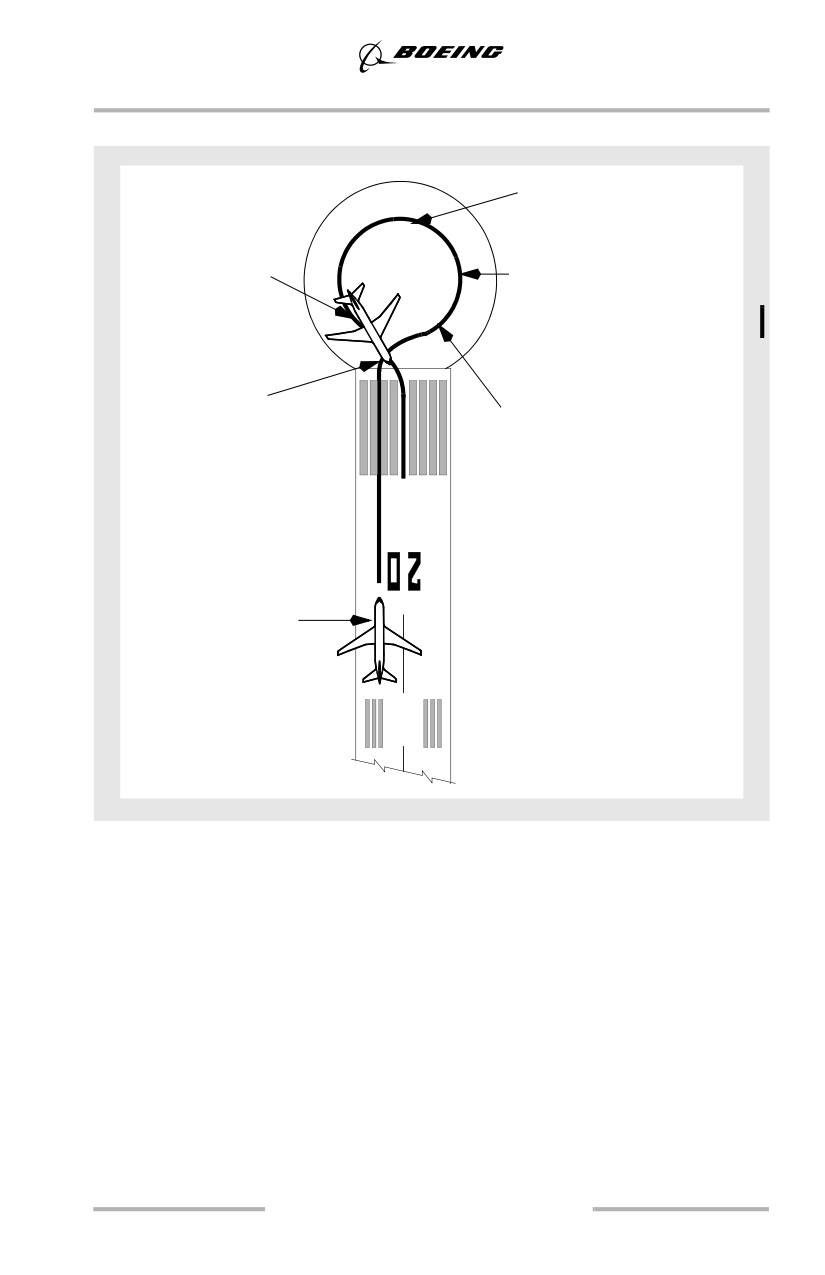
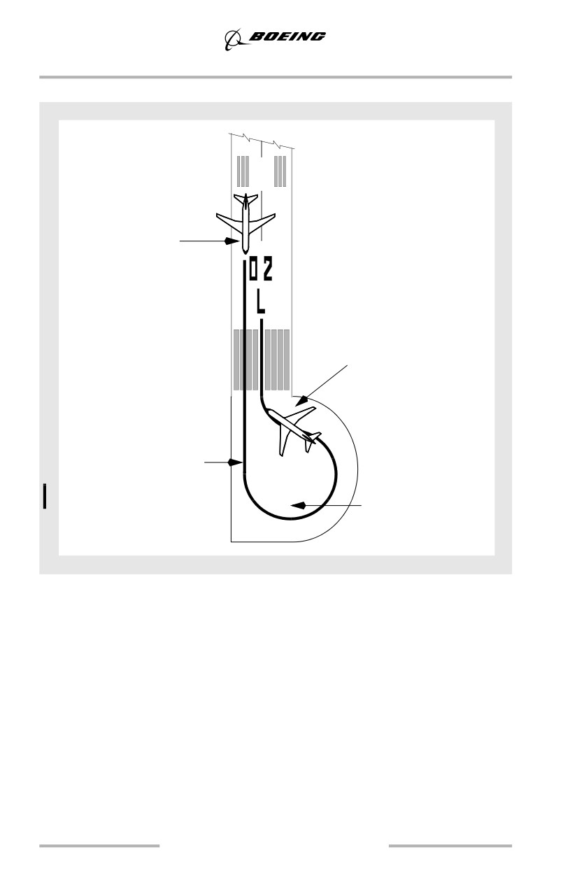
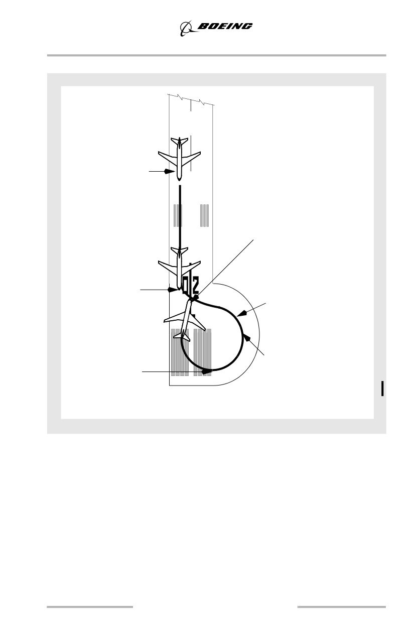
The following diagrams show suggested airplane ground tracks for minimum
radius 180° turns with various runway turnaround configurations. These ground
tracks provide the best maneuver capability while providing the maximum
runway length available for takeoff at the completion of the turn. However, this
type of maneuvering is normally not required unless operating on runways less
than 148 feet (45m) in width.
2.8
Ground Operations
Techniques when using a Circular Turnaround
When turn completion
Use momentary
is assured and main
application of inside
gear are on the runway
brakes, as needed
centerline, steer toward
runway centerline.
When abeam center of the
turnaround, stop the
airplane, apply full steering
wheel then add thrust to
maintain 5 to 10 knots
during the turn.
After entering the
turnaround, turn to align
Steer to maintain flight
airplane near opposite
deck over edge of taxi
side of circular
surface. Maintain 5 to 10
turnaround
knots.
Align airplane
near runway edge
Note: Follow turnaround
steering guidance
cues if available
2.9
Ground Operations
Techniques when using a Hammerhead Turnaround
Note: Follow turnaround
steering guidance
cues if available
Align airplane
near runway edge
When turn completion
is assured and main
gear are on the runway
centerline, steer toward
runway centerline.
When abeam center of the
turnaround, stop the
airplane, apply full steering
wheel, then add thrust to
Use momentary
maintain 5 to 10 knots
application of inside
during the turn.
brakes, as needed
2.10
Ground Operations
Techniques when using a Hammerhead Turnaround
Note: Follow turnaround
steering guidance
cues if available
Align airplane
near runway edge
When turn completion
is assured and main
gear are on the runway
centerline, steer toward
runway centerline.
After entering the
turnaround, turn to
Steer to place the nose
align airplane near
wheels near the edge
opposite side of
of the taxi surface
circular turnaround
Use momentary
When abeam center of
application of inside
the turnaround, stop the
brakes, as needed
airplane, apply full
steering wheel, then add
thrust to maintain 5 to
10 knots during the turn.
Taxi - Adverse Weather
Taxi under adverse weather conditions requires more awareness of surface
conditions.
2.11
Ground Operations
When taxiing on a slippery or contaminated surface, particularly with strong
crosswinds, use reduced speeds. Use of differential engine thrust assists in
maintaining airplane momentum through the turn. When nearing turn completion,
placing both engines to idle thrust reduces the potential for nose gear skidding.
Avoid using large nose wheel steering inputs to correct for skidding. Differential
braking may be more effective than nose wheel steering on slippery or
contaminated surfaces. If speed is excessive, reduce speed prior to initiating a
turn.
Note: A slippery surface is any surface where the braking capability is less than
that on a dry surface. Therefore, a surface is considered “slippery” when it
is wet or contaminated with ice, standing water, slush, snow or any other
deposit that results in reduced braking capability.
During cold weather operations, nose gear steering should be exercised in both
directions during taxi. This circulates warm hydraulic fluid through the steering
cylinders and minimizes the steering lag caused by low temperatures. If icing
conditions are present, use anti-ice as required by the FCOM.
During prolonged ground operations, periodic engine run-ups should be
accomplished to minimize ice build-up. These engine run-ups should be
performed as defined in the FCOM.
Engine exhaust may form ice on the ramp and takeoff areas of the runway, or blow
snow or slush which may freeze on airplane surfaces. If the taxi route is through
slush or standing water in low temperatures, or if precipitation is falling with
temperatures below freezing, taxi with flaps up. Extended or prolonged taxi times
in heavy snow may necessitate de-icing prior to takeoff.
To reduce the possibility of flap damage after making an approach in icing
conditions or landing on a runway covered with snow or slush, do not retract the
flaps to less than 15 until the flap area has been checked for debris by
maintenance.
Low Visibility
Pilots need a working knowledge of airport surface lighting, markings, and signs
for low visibility taxi operations. Understanding the functions and procedures to
be used with stop bar lights, ILS critical area markings, holding points, and low
visibility taxi routes is essential to conducting safe operations. Many airports have
special procedures for low visibility operations. For example, airports operating
under FAA criteria with takeoff and landing minimums below 1200ft (350m) RVR
are required to have a low visibility taxi plan.
2.12
Ground Operations
Taxi - One Engine
Because of additional operational procedural requirements and crew workload,
taxiing out for flight with an engine shut down is not recommended. High bypass
engines require warm up prior to applying takeoff thrust and cool down prior to
shutting down. If the engine has been shut down for several hours, it is desirable
to operate at as low a thrust setting as practical for several minutes prior to takeoff.
If an engine is shutdown during taxi in after flight, the crew must be aware of
systems requirements, (hydraulics, brakes, electrical). The APU should be
operating while taxiing with an engine shutdown. If possible, make minimum
radius turns in a direction that puts the operating engine on the outside of the turn.
In operational environments such as uphill slope, soft asphalt, high gross weights,
congested ramp areas, and wet/slippery ramps and taxiways, taxi with both
engines operating.
2.13
Ground Operations
Intentionally
Blank
2.14
Takeoff and Initial Climb
Chapter 3
Table of Contents
Section TOC
3.TOC Takeoff and Initial Climb-Table of Contents
Preface
3.1
Takeoff
3.2
Takeoff Profile
3.2
Takeoff - General
3.3
Thrust Management
3.3
Initiating Takeoff Roll
3.3
Rotation and Liftoff - All Engines
3.7
Effect of Rotation Speed and Pitch Rate on Liftoff
3.10
Center-Of-Gravity (CG) Effects
3.11
Crosswind Takeoff
3.12
Takeoff Crosswind Guidelines
3.12
Directional Control
3.13
Rotation and Takeoff
3.13
Gusty Wind and Strong Crosswind Conditions
3.13
Reduced Thrust Takeoff
3.14
Assumed Temperature Method (ATM)
3.14
Fixed Derate
3.15
Combination Fixed Derate and ATM
3.15
Improved Climb Performance Takeoff
3.15
Low Visibility Takeoff
3.16
Adverse Runway Conditions
3.16
Effect of Deicing/Anti-Icing Fluids on Takeoff
3.17
Federal Aviation Regulation (FAR) Takeoff Field Length
3.17
FAR Takeoff
3.18
3.TOC.1
Takeoff and Initial Climb -
Table of Contents
Rejected Takeoff Decision
3.19
Rejected Takeoff Maneuver
3.20
Go/Stop Decision Near V1
3.20
RTO Execution Operational Margins
3.21
Initial Climb - All Engines
3.24
Minimum Fuel Operation - Takeoff
3.24
Immediate Turn after Takeoff - All Engines
3.24
Roll Modes
3.25
Autopilot Engagement
3.25
Flap Retraction Schedule
3.25
Noise Abatement Takeoff
3.26
Takeoff - Engine Failure
3.27
General
3.27
Engine Failure Recognition
3.27
Rotation and Liftoff - One Engine Inoperative
3.27
Initial Climb - One Engine Inoperative
3.31
Immediate Turn after Takeoff - One Engine Inoperative
3.31
Autopilot Engagement - One Engine Inoperative
3.31
Flap Retraction - One Engine Inoperative
3.32
Flaps Up - One Engine Inoperative
3.32
Noise Abatement - One Engine Inoperative
3.32
Engine Failure During an ATM Takeoff
3.32
Engine Failure During a Fixed Derate Takeoff
3.33
Engine Failure During a Combined Takeoff
3.33
3.TOC.2
Takeoff and Initial Climb
Chapter 3
Preface
This chapter outlines the recommended operating practices and techniques for
takeoff and initial climb. Engine failure during takeoff/initial climb is also
addressed. The discussion portion of each illustration highlights important
information.
The flight profile illustrations represent the recommended basic configuration
during the accomplishment of the flight maneuvers, and provides a basis for
standardization and crew coordination.
3.1
Takeoff and Initial Climb
Takeoff
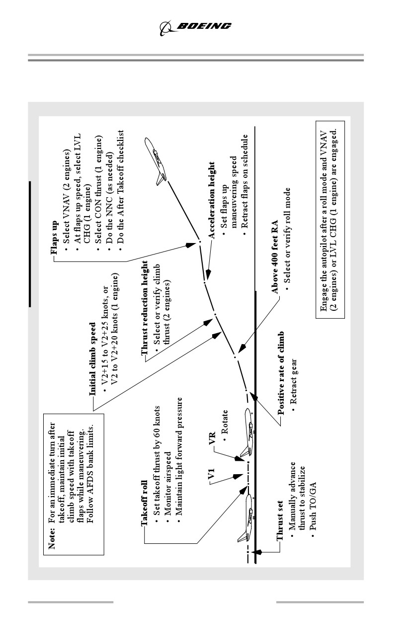
Takeoff Profile
3.2
Takeoff and Initial Climb
Takeoff - General
Normal takeoff procedures satisfy typical noise abatement requirements. Some
airports may have special procedures which require modification of the takeoff
profile.
As part of the before start procedure, review the TAKEOFF REF page to ensure
the entries are correct and the preflight is complete. Ensure V2 is set on the MCP.
The map display, map range and LEGS page sequence should be consistent with
the departure procedure.
Review the LEGS page for any climb constraints. Ensure the CLB page contains
the appropriate altitude and airspeed restrictions consistent with the departure
procedure.
Note: The lower center MFD is normally blank for takeoff to reduce display of
unnecessary information.
Although flaps up speed to 3,000 feet is generally recommended for noise
abatement reasons, it may not be required except at heavy weights. At lighter
weights the performance of the airplane is such that 3,000 feet is usually reached
before flap retraction is complete.
The PF should normally display the TAKEOFF REF page. To reduce heads down
activity, climb constraint modification immediately after takeoff should normally
be accomplished on the mode control panel. Modify the CLB page when workload
permits. The PM should display the LEGS page of the FMC for departure to allow
timely route modification if necessary.
Thrust Management
The Electronic Engine Control (EEC) simplifies thrust management procedures.
Having the EEC functioning does not relieve the pilots from monitoring the
engine parameters and verifying proper thrust is obtained.
High thrust settings from jet engine blast over unpaved surfaces or thin asphalt
pavement intended only to support occasional airplane movements can cause
structural blast damage from loose rocks, dislodged asphalt pieces, and other
foreign objects. Ensure run ups and takeoff operations are only conducted over
well maintained paved surfaces and runways.
Initiating Takeoff Roll
Autothrottle and flight director use is recommended for all takeoffs. However, do
not follow F/D commands until after liftoff.
3.3
Takeoff and Initial Climb
A rolling takeoff procedure is recommended for setting takeoff thrust. It expedites
the takeoff and reduces the risk of foreign object damage or engine surge/stall due
to a tailwind or crosswind. Flight test and analysis prove that the change in takeoff
roll distance due to the rolling takeoff procedure is negligible when compared to
a standing takeoff.
Rolling takeoffs are accomplished in two ways:
• if cleared for takeoff before or while entering the runway, maintain
normal taxi speed. When the airplane is aligned with the runway
centerline ensure the nose wheel steering wheel is released and apply
takeoff thrust by advancing the thrust levers to just above idle (40%N1).
Allow the engines to stabilize momentarily then promptly advance the
thrust levers to takeoff thrust (autothrottle TO/GA). There is no need to
stop the airplane before increasing thrust.
• if holding in position on the runway, ensure the nose wheel steering wheel
is released, release brakes, then apply takeoff thrust as described above.
Note: Brakes are not normally held with thrust above idle unless a static run-up
in icing conditions is required.
A standing takeoff procedure may be accomplished by holding the brakes until the
engines are stabilized, ensure the nose wheel steering wheel is released, then
release the brakes and promptly advance the thrust levers to takeoff thrust
(autothrottle TO/GA).
Allowing the engines to stabilize provides uniform engine acceleration to takeoff
thrust and minimizes directional control problems. This is particularly important
if crosswinds exist or the runway surface is slippery. The exact initial setting is not
as important as setting symmetrical thrust.
Note: Allowing the engines to stabilize for more than approximately 2 seconds
before advancing thrust levers to takeoff thrust may adversely affect
takeoff distance.
If thrust is to be set manually, smoothly advance thrust levers toward takeoff
thrust. Final thrust adjustments should be made, with reference to the digital
readouts, by 60 knots.
During takeoff, if an engine exceedance occurs after thrust is set and the decision
is made to continue the takeoff, do not retard the thrust lever in an attempt to
control the exceedance. Retarding the thrust levers after thrust is set invalidates
takeoff performance. When the PF judges that altitude (minimum 400 feet AGL)
and airspeed are acceptable, the thrust lever should be retarded until the
exceedance is within limits and the appropriate NNC accomplished.
3.4
Takeoff and Initial Climb
Use of the nose wheel steering wheel is not recommended above 30 knots.
However, pilots must use caution when using the nose wheel steering wheel above
20 knots to avoid over-controlling the nose wheels resulting in possible loss of
directional control. Limited circumstances such as inoperative rudder pedal
steering may require the use of the nose wheel steering wheel at low speeds during
takeoff and landing when the rudder is not effective. Reference the airplane
Dispatch Deviations Guide (DDG) for more information concerning operation
with rudder pedal steering inoperative.
Light forward pressure is held on the control column. Keep the airplane on
centerline with rudder pedal steering and rudder. The rudder becomes effective
between 40 and 60 knots. Maximum nose wheel steering effectiveness is available
when above taxi speeds by using rudder pedal steering.
Regardless of which pilot is making the takeoff, the captain should keep one hand
on the thrust levers until V1 in order to respond quickly to a rejected takeoff
condition. After V1, the captain’s hand should be removed from the thrust levers.
The PM should monitor engine instruments and airspeed indications during the
takeoff roll and announce any abnormalities. The PM should announce passing 80
knots and the PF should verify that his airspeed indicator is in agreement.
A pitot system blocked by protective covers or foreign objects can result in no
airspeed indication, or airspeed indications that vary between instruments. It is
important that aircrews ensure airspeed indicators are functioning and reasonable
at the 80 knot callout. If the accuracy of either primary airspeed indication is in
question, reference the standby airspeed indicator. Another source of speed
information is the ground speed indication. Early recognition of a malfunction is
important in making a sound go/stop decision. Refer to the Airspeed Unreliable
section in chapter 8 for an expanded discussion of this subject.
The PM should verify that takeoff thrust has been set and the throttle hold mode
(THR HLD) is engaged. A momentary autothrottle overshoot of 4% N1 may occur
but thrust should stabilize at +/- 2% N1, after THR HLD. Thrust should be
adjusted by the PM, if required, to - 0% + 1% target N1. Once THR HLD
annunciates, the autothrottle cannot change thrust lever position, but thrust levers
can be positioned manually. The THR HLD mode remains engaged until another
thrust mode is selected.
Note: Takeoff into headwind of 20 knots or greater may result in THR HLD
before the autothrottle can make final thrust adjustments.
3.5
Takeoff and Initial Climb
The THR HLD mode protects against thrust lever movement if a system fault
occurs. Lack of the THR HLD annunciation means the protective feature may not
be active. If THR HLD annunciation does not appear, no crew action is required
unless a subsequent system fault causes unwanted thrust lever movement. As with
any autothrottle malfunction, the autothrottle should then be disconnected and
desired thrust set manually.
If full thrust is desired when THR HLD mode is displayed, the thrust levers must
be manually advanced. When making a V1(MCG)-limited takeoff, do not exceed
the fixed derate thrust limit except in an emergency.
After the airplane is in the air, pushing a TO/GA switch advances the thrust to
maximum available thrust and TO/GA is annunciated.
Initiating Takeoff Roll Using HUD System
Normal procedures apply, however, pilots must be aware that the captain’s
attention is devoted almost exclusively to outside/HUD cues. This requires that
the first officer’s attention be devoted to head down instruments more than during
the normal takeoff roll.
The captain monitors the takeoff roll by using visual cues and HUD symbology.
Use HUD guidance symbology, runway lighting and runway markings to maintain
runway centerline. Rotate using the airplane reference symbol on the HUD.
3.6
Takeoff and Initial Climb
Rotation and Liftoff - All Engines
Takeoff speeds are established based on minimum control speed, stall speed, and
tail clearance margins. Shorter bodied airplanes are normally governed by stall
speed margin while longer bodied airplanes are normally limited by tail clearance
margin. When a smooth continuous rotation is initiated at VR, tail clearance
margin is assured because computed takeoff speeds depicted in the QRH, airport
analysis, or FMC, are developed to provide adequate tail clearance.
Above 80 knots, relax the forward control column pressure to the neutral position.
For optimum takeoff and initial climb performance, initiate a smooth continuous
rotation at VR toward 15° of pitch attitude. The use of stabilizer trim during
rotation is not recommended. After liftoff use the flight director as the primary
pitch reference cross checking indicated airspeed and other flight instruments.
Note: Do not adjust takeoff speeds or rotation rates to compensate for increased
body length.
With a consistent rotation technique, where the pilot uses approximately equal
control forces and similar visual cues, the resultant rotation rate differs slightly
depending upon airplane body length.
Using the technique above, liftoff attitude is achieved in approximately 3 to 4
seconds. Resultant rotation rates vary from 2 to 3 degrees/second with rates being
lowest on longer airplanes.
Note: The flight director pitch command is not used for rotation.
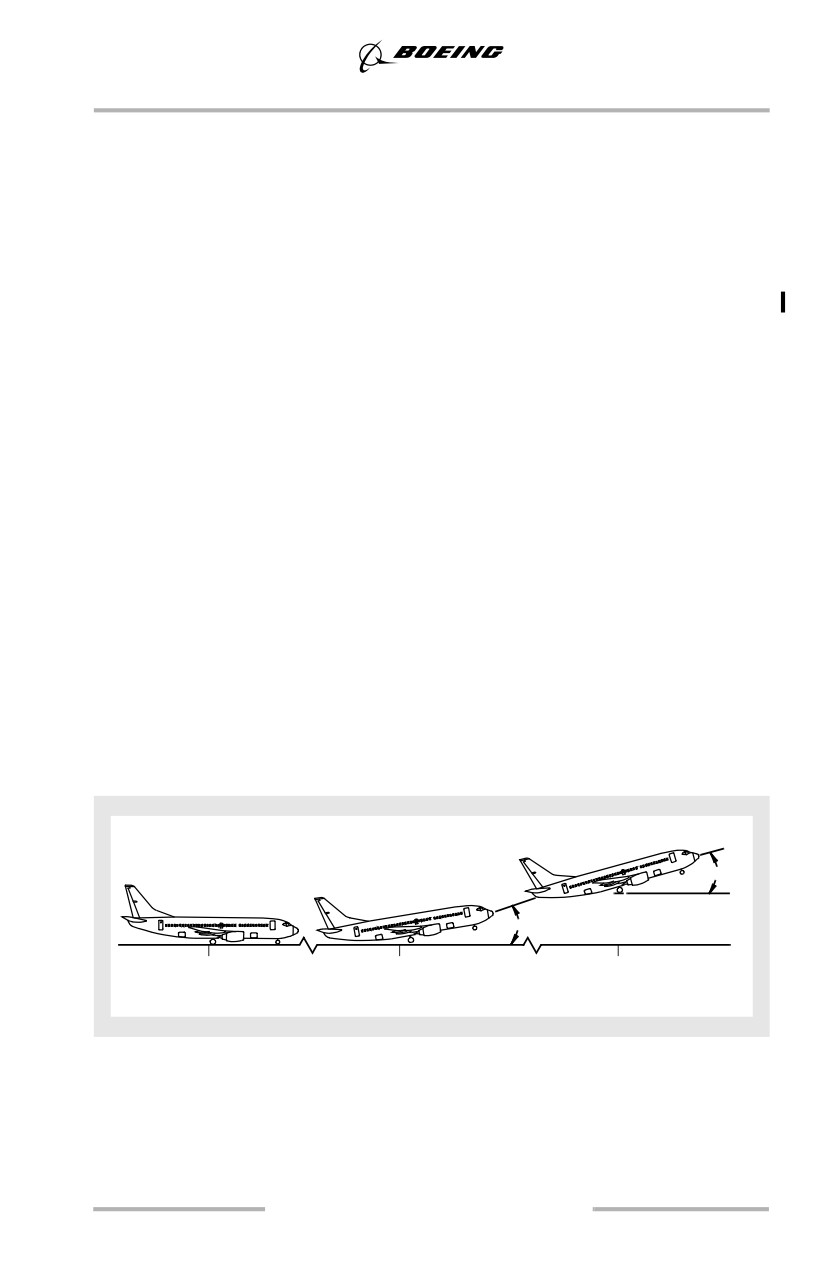
Typical Rotation, All Engines
The following figure shows typical rotation with all engines operating.
Liftoff
V
+ 15
V R
2
15-16°
35 ft.
7 - 9°
0
3
6.5
Time Seconds
Retract the landing gear after a positive rate of climb is indicated on the altimeter.
Retract flaps in accordance with the technique described in this chapter.
3.7
Takeoff and Initial Climb
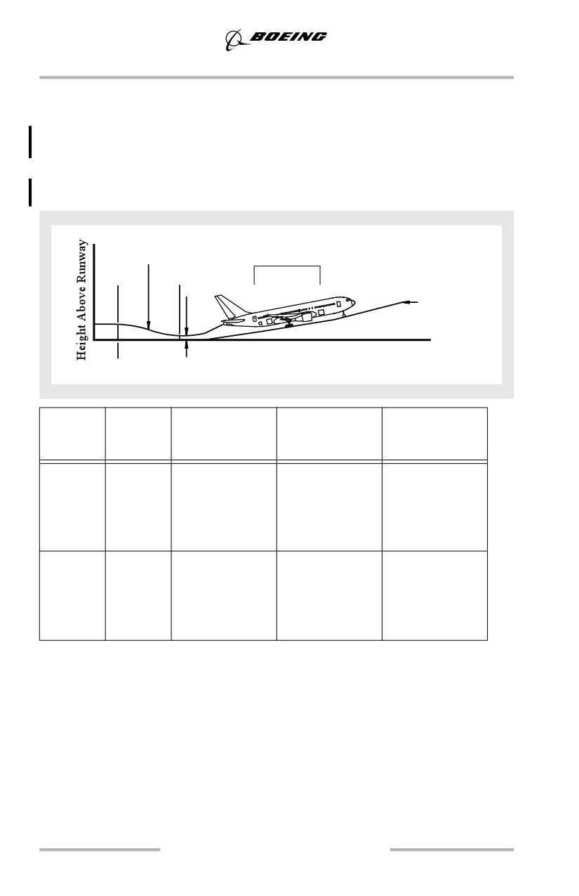
Typical Takeoff Tail Clearance
The following diagram and table show the effect of flap position on liftoff pitch
attitude and minimum tail clearance during takeoff. Additionally, the last column
shows the pitch attitude for tail contact with wheels on the runway and landing
gear struts extended. For a discussion of tail strike procedures see chapter 8 and
the FCOM.
Tail clearance height
TYPICAL
V R
V LOF
Gear height
Time
Min. tail clearance
Model
Flap
Liftoff Attitude
Minimum Tail
Tail Strike Pitch
(degrees)
Clearance
Attitude
inches (cm)
(degrees)
737-600
1
9.0
28 (71)
5
9.0
28 (71)
10
8.8
29 (73)
16.2
15
8.7
30 (76)
25
8.6
32 (81)
737-700
1
9.1
29 (73)
5
9.1
29 (73)
10
8.9
30 (76)
14.7
15
8.7
31 (79)
25
8.5
32 (81)
3.8

Takeoff and Initial Climb
Model
Flap
Liftoff Attitude
Minimum Tail
Tail Strike Pitch
(degrees)
Clearance
Attitude
inches (cm)
(degrees)
737-800
1
8.2
20 (51)
5
8.2
20 (51)
10
8.0
22 (56)
11.0
15
7.8
23 (58)
25
7.6
25 (64)
737-900
1
7.7
20 (51)
5
7.6
20 (51)
10
7.4
22 (56)
10.0
15
7.2
23 (58)
25
7.0
25 (64)
Note: Flaps 1 and 5 (-800/900) takeoffs have the least clearance. Consider
using a larger flap setting for takeoffs at light gross weights.
Because of the short fuselage, aft fuselage contact is unlikely in the
737-600.
3.9
Takeoff and Initial Climb
Effect of Rotation Speed and Pitch Rate on Liftoff
Takeoff and initial climb performance depend on rotating at the correct airspeed
and proper rate to the rotation target attitude. Early or rapid rotation may cause a
tail strike. Late, slow, or under-rotation increases takeoff ground roll. Any
improper rotation decreases initial climb flight path.
An improper rotation can have an effect on the command speed after liftoff. If the
rotation is delayed beyond V2 + 20, the speed commanded by the flight director
is rotation speed up to a maximum of V2 + 25. An earlier liftoff does not affect the
commanded initial climb speed, however, either case degrades overall takeoff
performance.
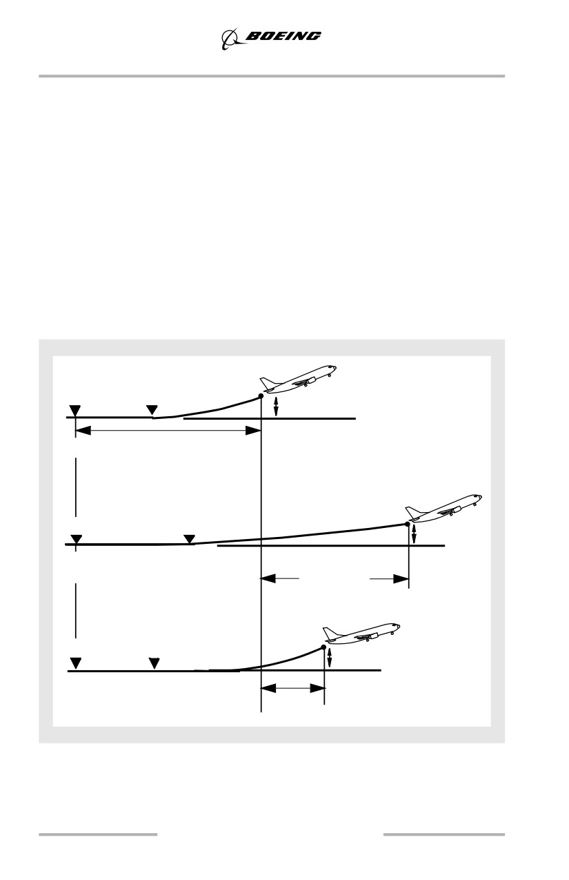
The following diagram shows how a slow or under rotation during takeoff
increases the distance to a height of 35 feet compared to a normal rotation.
Slow or Under Rotation (Typical)
VR
Liftoff
35'
Normal rotation
VR
Liftoff
35'
Slow rotation
(1° per sec slower than normal)
Up to 1000’
VR
Liftoff
35'
Under rotation
(Rotate to 5° less than target)
Up to 200’
3.10
Takeoff and Initial Climb
Center-Of-Gravity (CG) Effects
When taking off at light weight and with an aft CG, the combination of full thrust,
rapid thrust application, and sudden brake release may tend to pitch the nose up,
reducing nosewheel steering effectiveness. With CG at or near the aft limit,
maintain forward pressure on the control column until 80 knots to increase
nosewheel steering effectiveness. Above 80 knots, relax the forward control
column pressure to the neutral position. At light weight and aft CG, use of reduced
thrust and rolling takeoff technique is recommended whenever possible. The
rudder becomes effective between 40 and 60 knots.
Operation with Alternate Forward Center of Gravity Limit for Takeoff
Takeoff performance is based on the forward CG limitations as defined in the
AFM. However, takeoff performance can be improved by taking credit for an
alternate (further aft) forward CG limit if shown in the AFM. Use of this data
provides higher performance-limited takeoff weights than the basic AFM
performance data.
Typically alternate forward CG is used to increase performance-limited takeoff
weight for field length, climb or obstacle limited departures. Another potential
benefit of alternate forward CG is to allow greater thrust reduction which
increases engine reliability and reduces engine maintenance costs. However, this
improved performance capability is only available if the airline has the certified
data in their AFM and has approval from their regulatory agency to operate the
airplane at an alternate forward CG limit.
A more aft CG increases the lift available at a given angle of attack due to the
reduction in nose up trim required from the horizontal stabilizer. This allows VR
and V2 to be reduced, which in turn reduces the field length required for takeoff.
Reduction in field length required can also permit an increased field length limited
weight. In most instances this reduction in nose up trim also results in a decrease
in drag which improves the airplane’s climb capability.
Note: The FMC calculated takeoff speeds and QRH takeoff speeds are not valid
for operations using alternate forward CG. Takeoff speeds must be
calculated using alternate forward CG performance data normally
provided by dispatch or flight operations.
3.11
Takeoff and Initial Climb
Crosswind Takeoff
The crosswind guidelines shown below were derived through flight test data,
engineering analysis, and flight simulator evaluations.
Note: Engine surge can occur with a strong crosswind component if takeoff
thrust is set before brake release. Therefore, the rolling takeoff procedure
is strongly advised when crosswinds exceed 20 knots.
Takeoff Crosswind Guidelines
Crosswind guidelines are not considered limitations. Crosswind guidelines are
provided to assist operators in establishing their own crosswind policies.
Takeoff crosswind guidelines are based on the most adverse airplane loading (light
weight and aft center of gravity) and assume an engine out RTO and proper pilot
technique. On slippery runways, crosswind guidelines are a function of runway
surface condition.
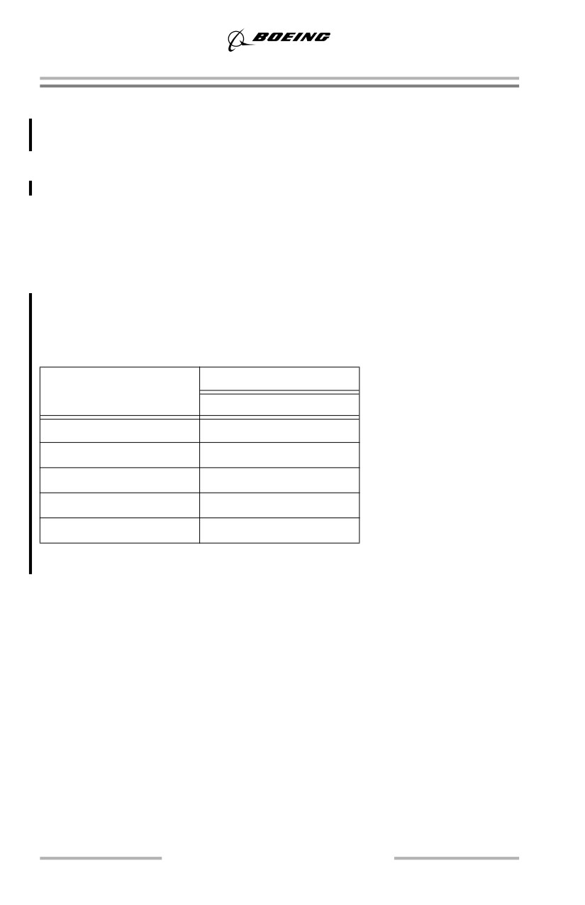
Crosswind - Knots*
Runway Condition
without / with winglets
Dry
36 / 34
Wet
25
Standing Water/Slush
15
Snow - No Melting **
25
Ice - No Melting **
15
*Winds measured at 33 feet (10 m) tower height and apply for runways 148 feet
(45m) or greater in width.
** Takeoff on untreated ice or snow should only be attempted when no melting is
present.
3.12
Takeoff and Initial Climb
Directional Control
Initial runway alignment and smooth symmetrical thrust application result in good
crosswind control capability during takeoff. Light forward pressure on the control
column during the initial phase of takeoff roll (below approximately 80 knots)
increases nose wheel steering effectiveness. Any deviation from the centerline
during thrust application should be countered with immediate smooth and positive
control inputs. Smooth rudder control inputs combined with small control wheel
inputs result in a normal takeoff with no overcontrolling. Large control wheel
inputs can have an adverse effect on directional control near V1(MCG) due to the
additional drag of the extended spoilers.
Note: With wet or slippery runway conditions, the PM should give special
attention to ensuring the engines have symmetrically balanced thrust
indications.
Rotation and Takeoff
Maintain wings level during the takeoff roll by applying control wheel
displacement into the wind. During rotation continue to apply control wheel in the
displaced position to keep the wings level during liftoff. The airplane is in a
sideslip with crossed controls at this point. A slow, smooth recovery from this
sideslip is accomplished after liftoff by slowly neutralizing the control wheel and
rudder pedals.
Gusty Wind and Strong Crosswind Conditions
For takeoff in gusty or strong crosswind conditions, use of a higher thrust setting
than the minimum required is recommended. When the prevailing wind is at or
near 90° to the runway, the possibility of wind shifts resulting in gusty tailwind
components during rotation or liftoff increases. During this condition, consider the
use of thrust settings close to or at maximum takeoff thrust. The use of a higher
takeoff thrust setting reduces the required runway length and minimizes the
airplane exposure to gusty conditions during rotation, liftoff, and initial climb.
3.13
Takeoff and Initial Climb
Avoid rotation during a gust. If a gust is experienced near VR, as indicated by
stagnant airspeed or rapid airspeed acceleration, momentarily delay rotation. This
slight delay allows the airplane additional time to accelerate through the gust and
the resulting additional airspeed improves the tail clearance margin. Do not rotate
early or use a higher than normal rotation rate in an attempt to clear the ground
and reduce the gust effect because this reduces tail clearance margins. Limit
control wheel input to that required to keep the wings level. Use of excessive
control wheel may cause spoilers to rise which has the effect of reducing tail
clearance. All of these factors provide maximum energy to accelerate through
gusts while maintaining tail clearance margins at liftoff. The airplane is in a
sideslip with crossed controls at this point. A slow, smooth recovery from this
sideslip is accomplished after liftoff by slowly neutralizing the control wheel and
rudder pedals.
Reduced Thrust Takeoff
Many operators prefer a less than maximum thrust takeoff whenever performance
limits and noise abatement procedures permit. The reduced thrust takeoff lowers
EGT and extends engine life.
The reduced thrust takeoff may be done using the Assumed Temperature Method,
a Fixed Derate, or a combination of both. Regardless of the method, use the
takeoff speeds provided by the airport analysis, FMC (if available), QRH (PI
chapter), Flight Planning and Performance Manual (FPPM), AFM, or other
approved source corresponding to the assumed (higher) temperature and/or
selected derate.
Assumed Temperature Method (ATM)
This method achieves a takeoff thrust less than the maximum takeoff thrust by
assuming a temperature that is higher than the actual temperature. The thrust
reduction authorized by most regulatory agencies is limited to 25% below the
maximum takeoff thrust.
The primary thrust setting parameter (N1) is not considered a limitation. If
conditions are encountered during the takeoff where additional thrust is desired,
such as windshear, the crew should not hesitate to manually advance thrust levers
to maximum takeoff thrust.
The assumed temperature method of computing reduced thrust takeoff
performance is always conservative and provides performance equal to or better
than the performance obtained if actually operating at the assumed temperature.
This is because the true airspeed of the airplane is lower than would be the case if
the actual temperature were equal to the assumed temperature.
3.14
Takeoff and Initial Climb
Do not use the ATM if conditions that affect braking such as a runway
contaminated by slush, snow, standing water, or ice exist, or if potential windshear
conditions exist. ATM procedures are allowed on a wet runway if suitable
performance accountability is made for the increased stopping distance on a wet
surface.
Note: An increase in elevator column force during rotation and initial climb may
be required for ATM takeoffs.
Fixed Derate
This method uses a takeoff thrust less than maximum takeoff thrust for which
complete and independent performance data are provided in the AFM. Derated
thrust is obtained by selection of a fixed takeoff derate in the FMC.
The fixed derate is considered a limitation for takeoff. Thrust levers should not be
advanced beyond the fixed derate limit unless conditions are encountered during
the takeoff where additional thrust is needed on both engines, such as windshear.
A thrust increase following an engine failure could result in a loss of directional
control.
Note: Although fixed derate takeoffs are permitted on wet or contaminated
runways, provided takeoff performance accounts for runway surface
conditions, they are not recommended if potential windshear conditions
exist.
Combination Fixed Derate and ATM
This method uses a takeoff thrust less than the fixed derate takeoff thrust by first
selecting a fixed takeoff derate from the FMC. This derate takeoff thrust is then
further reduced by assuming a temperature that is higher than the actual
temperature. In this case, the thrust reduction authorized by most regulatory
agencies is limited to 25% below the derated takeoff thrust.
Improved Climb Performance Takeoff
When not field length limited, an increased climb limit weight is achieved by
using the excess field length to accelerate to higher takeoff and climb speeds. This
improves the climb gradient, thereby raising the climb limit and obstacle limited
weights. V1, VR and V2 are increased to maintain consistent performance
relationships. V1, VR and V2 must be obtained from dispatch or the airport
analysis.
3.15
Takeoff and Initial Climb
Low Visibility Takeoff
Low visibility takeoff operations, below landing minima, may require a takeoff
alternate. When selecting a takeoff alternate, consideration should be given to
unexpected events such as an engine failure or other non-normal situation that
could affect landing minima at the takeoff alternate. Operators, who have
authorization for engine inoperative Category II/III operations, may be authorized
lower alternate minima.
With proper crew training and appropriate runway lighting, takeoffs with visibility
as low as 500ft/150m RVR may be authorized (FAA). With takeoff guidance
systems and centerline lighting that meets FAA or ICAO criteria for Category III
operations, takeoffs with visibility as low as 300ft/75m RVR may be authorized.
Regulatory agencies may impose takeoff crosswind limits specifically for low
visibility takeoffs.
All RVR readings must be equal to or greater than required takeoff minima. If the
touchdown or rollout RVR system is inoperative, the mid RVR may be substituted
for the inoperative system. When the touchdown zone RVR is inoperative, pilot
estimation of RVR may be authorized by regulatory agencies.
Adverse Runway Conditions
Slush, standing water, or deep snow reduces the airplane takeoff performance
because of increased rolling resistance and the reduction in tire-to-ground friction.
Most operators specify weight reductions to the AFM field length and/or obstacle
limited takeoff weight based upon the depth of powdery snow, slush, wet snow or
standing water and a maximum depth where the takeoff should not be attempted.
Slush or standing water may cause damage to the airplane. The recommended
maximum depth for slush, standing water, or wet snow is 0.5 inch (12.7 mm) on
the runway. For dry snow the maximum depth is 4 inches (102 mm).
A slippery runway (wet, compact snow, ice) also increases stopping distance
during a rejected takeoff. Takeoff performance and critical takeoff data are
adjusted to fit the existing conditions. Check the airport analysis or the PI section
of the QRH for takeoff performance changes with adverse runway conditions.
Note: If there is an element of uncertainty concerning the safety of an operation
with adverse runway conditions, do not takeoff until the element of
uncertainty is removed.
During wet runway or slippery conditions, the PM must give special attention to
ensuring that the thrust on the engines advances symmetrically. Any tendency to
deviate from the runway centerline must immediately be countered with steering
action and, if required, slight differential thrust.
3.16
Takeoff and Initial Climb
Forward pressure on the control column during the initial portion of the takeoff
roll (below approximately 80 knots) increases nose wheel steering effectiveness.
During takeoffs on icy runways, lag in rudder pedal steering and possible nose
wheel skidding must be anticipated. Keep the airplane on the centerline with
rudder pedal steering and rudder. The rudder becomes effective between 40 - 60
knots. If deviations from the centerline cannot be controlled either during the start
of the takeoff roll or until the rudder becomes effective, immediately reject the
takeoff.
Effect of Deicing/Anti-Icing Fluids on Takeoff
Testing of undiluted Type II and Type IV fluids has shown that some of the fluid
remains on the wing during takeoff rotation and during initial climb out. The
residual fluid causes a temporary decrease in lift and increase in drag. These
effects are more significant at lower ambient temperatures where the fluid tends
to stay on the wing longer. Operators must comply with the lowest operational use
temperatures provided by the fluid manufacturer to ensure a relatively clean wing.
No performance adjustments are required for the application of deicing/anti-icing
fluids. Takeoff operations with reduced thrust based on derates and/or the assumed
temperature method are permitted. Use normal rotation rates.
Federal Aviation Regulation (FAR) Takeoff Field Length
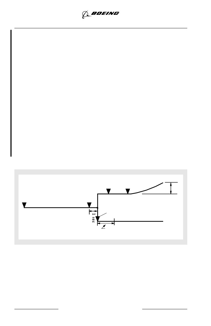
The FAR takeoff field length is the longest of the following:
• the distance required to accelerate with all engines, experience an engine
failure 1 second prior to V1, continue the takeoff and reach a point 35 feet
above the runway at V2 speed. (Accelerate-Go Distance).
• the distance required to accelerate with all engines, experience an event 1
second prior to V1, recognize the event, initiate the stopping maneuver
and stop within the confines of the runway (Accelerate-Stop Distance).
•
1.15 times the all engine takeoff distance required to reach a point 35 feet
above the runway.
Stopping distance includes the distance traveled while initiating the stop and is
based on the measured stopping capability as demonstrated during certification
flight test.
During certification, maximum manual braking and speedbrakes are used. Thrust
reversers are not used. Although reverse thrust and autobrakes are not used in
determining the FAR accelerate-stop distance, thrust reversers and RTO
autobrakes should be used during any operational rejected takeoff.
3.17
Takeoff and Initial Climb
Calculating a V1 speed that equates accelerate-go and accelerate-stop distances
defines the minimum field length required for a given weight. This is known as a
“balanced field length” and the associated V1 speed is called the “balanced V1”.
The QRH and FMC provide takeoff speeds based on a balanced V1. If either an
ATM or fixed derate reduced thrust takeoff is used, the QRH and FMC, if FMC
takeoff speeds are available, will provide a balanced V1 applicable to the lower
thrust setting.
Takeoff gross weight must not exceed the climb limit weight, field limit weight,
obstacle limit weight, tire speed limit, or brake energy limit. If the weight is
limited by climb, obstacle, or brake considerations, it may be beneficial to use
takeoff speeds that are different from the normal balanced takeoff speeds provided
by the QRH or FMC. Examples of this include the use of:
• improved climb to increase climb or obstacle limited weights
• maximum V1 policy to increase obstacle limited weights
• minimum V1 policy to increase brake energy limited weights
• clearway or stopway to increase field or obstacle limited weights.
If the takeoff weight is not based on normal balanced V1, the QRH and FMC
takeoff speeds are not applicable and the operator should provide the pilot with a
method to obtain the appropriate takeoff speeds.
FAR Takeoff
V 2
•
VR
V LOF
35'
V1
Brake
One Engine
Release
Event*
Acceleration
•
All Engine Acceleration
Brakes Applied
Stop
•
* For the continued takeoff,
Thrust levers idle and speedbrakes
the event is an engine failure
manually deployed
Note: The graphic above refers to dry runway conditions only. Refer to the AFM
for detailed wet runway performance information.
3.18
Takeoff and Initial Climb
Rejected Takeoff Decision
The total energy that must be dissipated during an RTO is proportional to the
square of the airplane velocity. At low speeds (up to approximately 80 knots), the
energy level is low. Therefore, the airplane should be stopped if an event occurs
that would be considered undesirable for continued takeoff roll or flight.
Examples include Master Caution, unusual vibrations or tire failure.
Note: Refer to the Rejected Takeoff NNM in the QRH for guidance concerning
the decision to reject a takeoff below and above 80 knots.
As the airspeed approaches V1 during a balanced field length takeoff, the effort
required to stop can approach the airplane maximum stopping capability.
Therefore, the decision to stop must be made before V1.
Historically, rejecting a takeoff near V1 has often resulted in the airplane stopping
beyond the end of the runway. Common causes include initiating the RTO after
V1 and failure to use maximum stopping capability (improper
procedures/techniques). Effects of improper RTO execution are shown in the
diagrams located in the RTO Execution Operational Margins section, this chapter.
The maximum braking effort associated with an RTO is a more severe level of
braking than most pilots experience in normal service.
Rejecting the takeoff after V1 is not recommended unless the captain judges the
airplane incapable of flight. Even if excess runway remains after V1, there is no
assurance that the brakes have the capacity to stop the airplane before the end of
the runway.
There have been incidents where pilots have missed FMC alerting messages
informing them that the takeoff speeds have been deleted or they have forgotten
to set the airspeed bugs. If, during a takeoff, the crew discovers that the V speeds
are not displayed and there are no other fault indications, the takeoff may be
continued. The lack of displayed V speeds with no other fault indications does not
fit any of the published criteria for rejecting a takeoff (refer to the Rejected
Takeoff NNM in the QRH). In the absence of displayed V speeds, the PM should
announce V1 and VR speeds to the PF at the appropriate times during the takeoff
roll. The V2 speed should be displayed on the MCP and primary airspeed
indicators. If neither pilot recalls the correct rotation speed, rotate the airplane 5
to 10 knots before the displayed V2 speed.
3.19
Takeoff and Initial Climb
Rejected Takeoff Maneuver
The RTO maneuver is initiated during the takeoff roll to expeditiously stop the
airplane on the runway. The PM should closely monitor essential instruments
during the takeoff roll and immediately announce abnormalities, such as
“ENGINE FIRE”, “ENGINE FAILURE”, or any adverse condition significantly
affecting safety of flight. The decision to reject the takeoff is the responsibility of
the captain, and must be made before V1 speed. If the captain is the PM, he should
initiate the RTO and announce the abnormality simultaneously.
Note: If the decision is made to reject the takeoff, the flight crew should
accomplish the rejected takeoff non-normal maneuver as described in the
Maneuvers chapter of the QRH.
If the takeoff is rejected before the THR HLD annunciation, the autothrottle
should be disengaged as the thrust levers are moved to idle. If the autothrottle is
not disengaged, the thrust levers advance to the selected takeoff thrust position
when released. After THR HLD is annunciated, the thrust levers, when retarded,
remain in idle. For procedural consistency, disengage the autothrottles for all
rejected takeoffs.
If rejecting due to fire, in windy conditions, consider positioning the airplane so
the fire is on the downwind side. After an RTO, comply with brake cooling
requirements before attempting a subsequent takeoff.
Go/Stop Decision Near V1
It was determined when the aviation industry produced the Takeoff Safety
Training Aid in 1992 that the existing definition of V1 might have caused
confusion because they did not make it clear that V1 is the maximum speed at
which the flight crew must take the first action to reject a takeoff. The U.S.
National Transportation Safety Board (NTSB) also noted in their 1990 study of
rejected takeoff accidents, that the late initiation of rejected takeoffs was the
leading cause of runway overrun accidents. As a result, the FAA has changed the
definition of V1 in FAR Part 1 to read as follows:
• V1 means the maximum speed in the takeoff at which the pilot must take
the first action (e.g., apply brakes, reduce thrust, deploy speedbrakes) to
stop the airplane within the accelerate-stop distance and
• V1 also means the minimum speed in the takeoff, following a failure of an
engine at which the pilot can continue the takeoff and achieve the required
height above the takeoff surface within the takeoff distance.
Pilots know that V1 is fundamental to making the Go/Stop decision. Under
runway limited conditions, if the reject procedure is initiated at V1, the airplane
can be stopped before reaching the end of the runway. See RTO Execution
Operational Margins diagrams for the consequences of initiating a reject after V1
and/or using improper procedures.
3.20
Takeoff and Initial Climb
When the takeoff performance in the AFM is produced, it assumes an engine
failure or event one-second before V1. In a runway limited situation, this means
the airplane reaches a height of 35 feet over the end of the runway if the decision
is to continue the takeoff.
Within reasonable limits, even if the engine failure occurs earlier than the assumed
one second before V1, a decision to continue the takeoff will mean that the
airplane is lower than 35 feet at the end of the runway, but it is still flying. For
example, if the engine fails 2 seconds before V1 and the decision is made to go,
the airplane will reach a height of 15 to 20 feet at the end of the runway.
Although training has historically centered on engine failures as the primary
reason to reject, statistics show engine thrust loss was involved in approximately
one quarter of the accidents, and wheel or tire problems have caused almost as
many accidents and incidents as have engine events. Other reasons that rejects
occurred were for configuration, indication or light, crew coordination problems,
bird strikes or ATC problems.
What's important to note here is that the majority of past RTO accidents were not
engine failure events. Full takeoff power from all engines was available. With
normal takeoff power, the airplane should easily reach a height of 150 feet over
the end of the runway, and the pilot has the full length of the runway to stop the
airplane if an air turnback is required.
Making the Go/Stop decision starts long before V1. Early detection, good crew
coordination and quick reaction are the keys to a successful takeoff or stop.
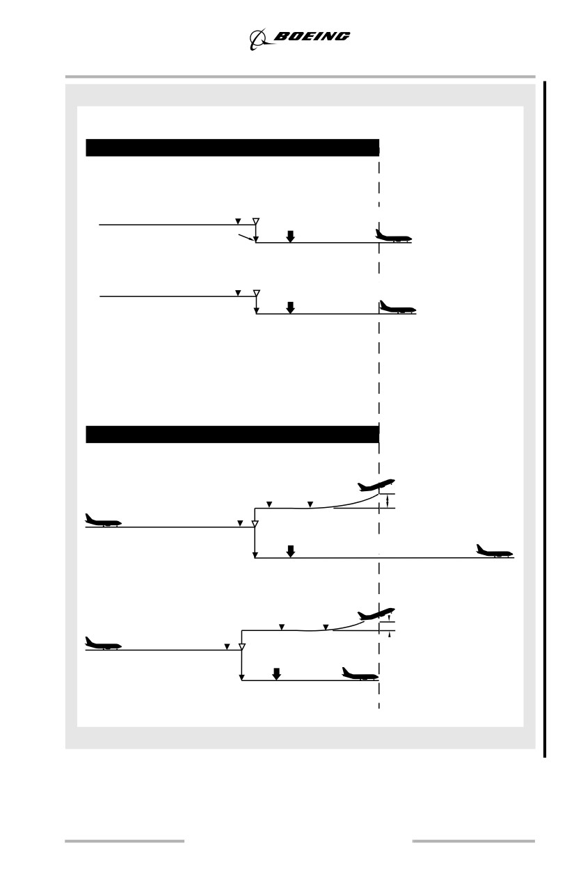
RTO Execution Operational Margins
A successful rejected takeoff at or near V1 is dependent upon the captain making
timely decisions and using the proper procedures.
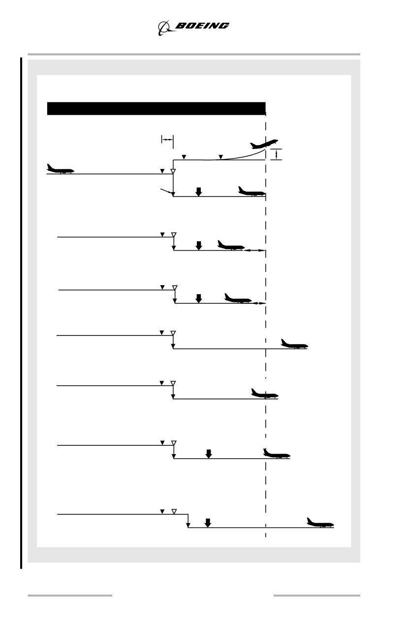
The data in the following diagrams, extracted from the Takeoff Safety Training
Aid, are provided as a reference. The individual diagrams show the approximate
effects of various configuration items and procedural variations on the stopping
performance of the airplane. These calculations are frequently based on estimated
data and are intended for training discussion purposes only. The data are generally
typical of the airplane at heavy weights, and except as noted otherwise, are based
on the certified transition time.
Each condition is compared to the baseline condition. The estimated speed at the
end of the runway and the estimated overrun distance are indicated at the right
edge of each figure. The distance estimates assume an overrun area that can
produce the same braking forces as the respective runway surface. If less than the
baseline FAA accelerate-stop distance is required, the distance is denoted as a
negative number.
3.21
Takeoff and Initial Climb
737
Available Runway (DRY)
Baseline
1 sec
V2
AFM balanced field length
All-engine RTO, brakes and
VR
Lift off
speedbrakes only, no thrust reverse
Go
35 ft
Event
One Engine Acceleration
V1Transition
complete
Brakes
Stop
No Go
Effect of reverse thrust
Engine-out RTO, brakes, speedbrakes,
and 1 thrust reverser
V1
-220 ft
Effect of reverse thrust
All-engine RTO, brakes, speedbrakes,
and 2 thrust reversers
V1
-150 ft
Effect of no speedbrakes
All-engine RTO, brakes only,
V1
no thrust reverse
60 kts
+430 ft
Effect of no speedbrakes
All-engine RTO, brakes and
V1
2 thrust reversers
35 kts
+120 ft
Effect of late speedbrakes
All-engine RTO, brakes, speedbrake
deployment 5 seconds after V1,
no thrust reverse
V1
50 kts
+250 ft
Effect of late RTO initiation
All-engine RTO initiated 2 seconds after V1,
AFM transition, brakes and speedbrakes
only, no thrust reverse
V1
75 kts
+690 ft
3.22
Takeoff and Initial Climb
737
Available Runway (DRY)
Effect of less than maximum
braking effort
All-engine RTO, 3/4 brake pressure,
speedbrakes, and 2 thrust reversers
EventV1
Transition
40 kts
complete
Brakes
+260 ft
Effect of blown tire
All-engine RTO, brakes, speedbrakes,
and 2 thrust reversers
V1
45 kts
+290 ft
Available Runway (WET)
Effect of using dry runway performance
V2
(limit weight and V1) on wet runway
All-engine RTO, brakes, speedbrakes,
VR
Lift off
35 ft
and 2 thrust reversers
One Engine Acceleration
V1
90 kts
+1070 ft
Effect of using wet runway
performance (reduced V1 and GW)
V2
Engine-out RTO, brakes, speedbrakes,
VR
and 1 thrust reverser
15 ft
One Engine Acceleration
V1
3.23
Takeoff and Initial Climb
Initial Climb - All Engines
After liftoff use the flight director as the primary pitch reference cross checking
indicated airspeed and other flight instruments. If the flight director is not used,
indicated airspeed and attitude become the primary pitch references.
After liftoff, the flight director commands pitch to maintain an airspeed of V2 +
20 knots until another pitch mode is engaged.
V2 + 20 is the optimum climb speed with takeoff flaps. It results in the maximum
altitude gain in the shortest distance from takeoff. Acceleration to higher speeds
reduces the altitude gain. If airspeed exceeds V2 + 20 during the initial climb, stop
the acceleration but do not attempt to reduce airspeed to V2 + 20. Any speed
between V2 + 15 and V2 + 25 knots results in approximately the same takeoff
profile. Crosscheck indicated airspeed for proper initial climb speed.
Retract the landing gear after a positive rate of climb is indicated on the altimeter.
Do not apply brakes after becoming airborne. Braking is automatically applied
when the landing gear lever is placed in the up position. After gear and flaps are
retracted, the PM should verify the gear and flaps indications are normal.
Minimum Fuel Operation - Takeoff
The minimum fuel recommended for takeoff is trip fuel plus reserves. On very
short flights this fuel quantity may not be enough to prevent forward fuel pump
low pressure lights from illuminating after takeoff.
If any main tank fuel pump indicates low pressure do not turn off fuel pump
switches. Avoid rapid acceleration of the airplane, reduce nose-up body attitude
and maintain minimum nose-up body angle required for a safe climb gradient.
Immediate Turn after Takeoff - All Engines
Obstacle clearance, noise abatement, or departure procedures may require an
immediate turn after takeoff. Initiate the turn at the appropriate altitude (normally
at least 400 feet AGL) and maintain V2 + 15 to V2 + 25 with takeoff flaps.
Note: A maximum bank angle of 30° is permitted at V2 + 15 knots with takeoff
flaps.
After completing the turn, and at or above flap retraction altitude, accelerate and
retract flaps while climbing.
Note: The possibility of an engine failure along the departure track must be
considered. Special engine out procedures, if available, are preferable to a
takeoff weight reduction to ensure all obstacles are cleared.
3.24
Takeoff and Initial Climb
Roll Modes
After takeoff and climb is stabilized, select LNAV (if not selected before takeoff)
after passing 400 feet AGL. If LNAV is selected for takeoff, LNAV guidance
becomes active at 50 feet AGL if the active leg is within 3.0 NM and 5° of the
runway heading. If the departure procedure or route does not begin at the end of
the runway, it may be necessary to use the HDG SEL mode at 400 feet AGL to
intercept the desired track for LNAV capture. When the departure procedure is not
a part of the active flight plan, use HDG SEL or VOR LOC mode. When an
immediate turn after takeoff is necessary, the desired heading may be preset before
takeoff.
Note: For all airplanes equipped with the HDG SEL takeoff option, leave runway
heading selected until turn initiation.
Navaids and appropriate radials or tracks required for use during the departure
may be displayed on the navigation display using the FIX page feature and/or
VOR/ADF switches on the EFIS control panel. Use of the STA and WPT switches
on the EFIS control panel provides additional information on the navigation
display.
Autopilot Engagement
The autopilot is FAA certified to allow engagement at or above 400 feet AGL after
takeoff. Other regulations or airline operating directives may specify a different
minimum altitude. The airplane should be in trim, and the flight director
commands should be satisfied before autopilot engagement. This prevents
unwanted changes from the desired flight path during autopilot engagement.
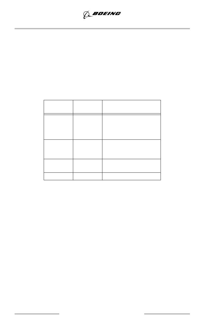
Flap Retraction Schedule
During training flights, 1,000 feet AFE is normally used as the acceleration height
to initiate thrust reduction and flap retraction. For noise abatement considerations
during line operations, thrust reduction typically occurs at approximately 1,500
feet AFE and acceleration typically occurs between 1,500 and 3,000 feet AFE, or
as specified by individual airport noise abatement procedures.
At thrust reduction altitude, select or verify that climb thrust is set. At acceleration
height, set flaps up maneuvering speed and retract flaps on the Flap Retraction
Schedule.
Begin flap retraction at V2 + 15 knots, except for a flaps 1 takeoff. For a flaps 1
takeoff, begin flap retraction when reaching the flaps 1 maneuvering speed.
With airspeed increasing, subsequent flap retractions should be initiated:
• when airspeed reaches the maneuvering speed (number) for the existing
flap position.
3.25
Takeoff and Initial Climb
For flaps up maneuvering, maintain at least:
•
“UP”
Note: The maneuver speed provides margin to stick shaker for at least an
inadvertent 15° overshoot beyond the normal 25° angle of bank.
With flaps up and above 3,000 feet AGL, select VNAV or set the desired climb
speed in the MCP speed window. Before selecting VNAV, flaps should be
retracted because VNAV does not provide overspeed protection for the leading
edge devices.
Takeoff Flap Retraction Speed Schedule
T/O
Select
Speed
Flaps
Flaps
(knots)
25
15
V2 + 15
5
“15”
1
“5”
UP
“1”
5
V2 + 15
15 or 10
1
“5”
UP
“1”
5
1
V2 + 15
UP
“1”
1
UP
“1”
•
“UP” - Flaps up maneuvering speed.
•
“1”, “5”, “10”, “15”, “25” - Number
corresponding to flap maneuvering speed.
Note: Limit bank angle to 15° until reaching V2 + 15.
Noise Abatement Takeoff
Normal takeoff procedures satisfy typical noise abatement requirements. Maintain
flaps up maneuvering speed until the noise abatement profile is satisfied, until
clear of obstacles or above any minimum crossing altitude. This is normally
achieved through the FMC speed restriction entered on the CLB page. It may be
also be accomplished using speed intervention (as installed) or LVL CHG.
Note: Specific local airport procedures should be followed.
3.26
Takeoff and Initial Climb
Takeoff - Engine Failure
General
Differences between normal and engine out profiles are few. One engine out
controllability is excellent during takeoff roll and after liftoff. Minimum control
speed in the air is below VR and VREF.
Engine Failure Recognition
An engine failure at or after V1 initially affects yaw much like a crosswind effect.
Vibration and noise from the affected engine may be apparent and the onset of the
yaw may be rapid.
The airplane heading is the best indicator of the correct rudder pedal input. To
counter the thrust asymmetry due to an engine failure, stop the yaw with rudder.
Flying with lateral control wheel displacement or with excessive aileron trim
causes spoilers to be raised.
Rotation and Liftoff - One Engine Inoperative
If an engine fails between V1 and liftoff, maintain directional control by smoothly
applying rudder proportionate with thrust decay.
During a normal all engine takeoff, a smooth continuous rotation toward 15° of
pitch is initiated at VR. With an engine inoperative, a smooth continuous rotation
is also initiated at VR; however, the target pitch attitude is approximately 2° to 3°
below the normal all engine pitch attitude. The rate of rotation with an engine
inoperative is also slightly slower (1/2° per second less) than that for a normal
takeoff. After liftoff adjust pitch attitude to maintain the desired speed.
If the engine failure occurs at or after liftoff apply rudder and aileron to control
heading and keep the wings level. In flight, correct rudder input approximately
centers the control wheel. To center the control wheel, rudder is required in the
direction that the control wheel is displaced. This approximates a minimum drag
configuration.
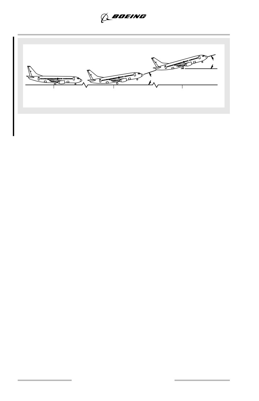
Typical Rotation - One Engine Inoperative
Liftoff attitude depicted in the following tables should be achieved in
approximately 5 seconds. Adjust pitch attitude, as needed, to maintain desired
airspeed of V2 to V2+20 knots.
3.27
Takeoff and Initial Climb
V R
Liftoff
V
to
V
+ 20
2
2
12-14°
35 ft.
7 - 11°
0
5
10 to 12
Time Seconds
Retract the landing gear after a positive rate of climb is indicated on the altimeter.
Retract flaps in accordance with the technique described in this chapter.
3.28
Takeoff and Initial Climb
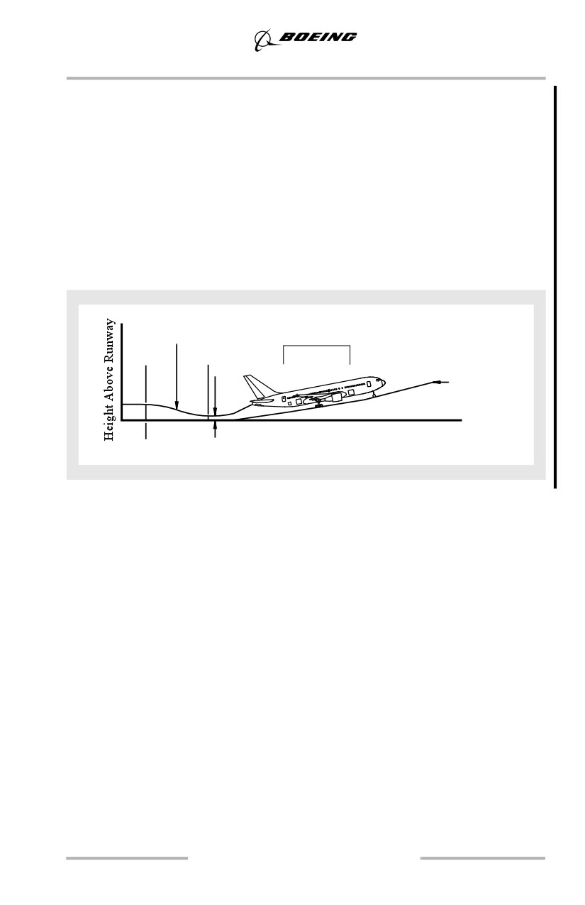
Typical Takeoff Tail Clearance - One Engine Inoperative
The following diagram and table show the effect of flap position on liftoff pitch
attitude and minimum tail clearance during takeoff with one engine inoperative.
Additionally, the last column shows the pitch attitude for tail contact with wheels
on the runway and landing gear struts extended. The tail strike pitch attitude
remains the same as during takeoffs with all engines operating. For a discussion
of tail strike procedures, see chapter 8 and the FCOM.
Note: Use of flap 1 as a takeoff flap setting is restricted to airplanes delivered
with this capability or to airplanes having flap 1 installed as a takeoff flap
setting.
Tail clearance height
TYPICAL
V R
V LOF
Gear height
Time
Min. tail clearance
3.29