Boeing 737 - 600/700/800/900. Flight Crew Training Manual (1999 year) - page 1
737 - 600/700/800/900
Flight Crew Training Manual
1999 The Boeing
Company
Document Number
April 1, 1999
Revision Number: 5
Revision Date: October 31, 2005
Copyright Information
Boeing claims copyright in each page of this document only to the extent that the page
contains copyrightable subject matter. Boeing also claims copyright in this document as a
compilation and/or collective work.
The right to reproduce, distribute, display, and make derivative works from this document,
or any portion thereof, requires a license from Boeing. For more information, contact The
Boeing Company, P.O. Box 3707, Seattle, Washington 98124.
Boeing 707, 717, 727, 737, 747, 757, 767, 777, DC-8, DC-9, DC-10, MD-10, MD-11,
MD-80, MD-90, BBJ, Boeing Business Jet, the Boeing logo symbol, and the
red-white-and-blue Boeing livery are all trademarks owned by The Boeing Company; and
no trademark license (either expressed or implied) is granted in connection with this
document or otherwise.
Preface
Chapter 0
Table of Contents
Section 0
0.0 Preface-Table of Contents
Title
Chapter
Preface
0
Table of Contents
0.0
Model Identification
0.1
Introduction
0.2
Abbreviations
0.3
Revision Record
0.4
List of Effective Pages
0.5
General Information
1
Ground Operations
2
Takeoff and Initial Climb
3
Climb, Cruise, Descent and Holding
4
Approach and Missed Approach
5
Landing
6
Maneuvers
7
Non-Normal Operations
8
Index
0.0.1
Preface -
Table of Contents
Intentionally
Blank
0.0.2
Preface
Chapter 0
Model Identification
Section 1
General
The airplane models listed in the table below are covered in this Flight Crew
Training Manual.
Model
737-600
737-700
737-800
737-900
Model numbers are used to distinguish information peculiar to one or more, but
not all of the airplanes. Where information applies to all models, no reference is
made to individual model numbers.
If information is applicable to consecutively numbered models, a dash (-) is used
in the model designator. For example, if information is applicable to 737-400 and
737-500 and 737-600 and 737-700 models, the model designator will show
737-400 - 737-700.
If information is applicable to models that are not consecutively numbered, a
comma (,) is used in the model designator. For example, if information is
applicable to only 737-300 and 737-800 models, the model designator will show
737-300, 737-800.
0.1.1
Preface -
Model Identification
Intentionally
Blank
0.1.2
Preface
Chapter 0
Introduction
Section 2
General
The Flight Crew Training Manual provides information and recommendations on
maneuvers and techniques. The manual is divided into eight chapters: General
Information; Ground Operations; Takeoff and Initial Climb; Climb, Cruise,
Descent and Holding; Approach and Missed Approach; Landing; Maneuvers; and
Non-Normal Operations.
General Information covers procedures and techniques not associated with a
particular maneuver or phase of flight. Ground Operations covers information
associated with airplane preflight, engine starting and taxi operations including
taxi operations in adverse weather conditions. Chapters 3 through 6 are titled by
phase-of-flight and contain information about airplane operations in each phase.
The Maneuvers chapter covers maneuvers associated with climb, cruise, and
descent, i.e., stall recovery and emergency descent. The Non-Normal Procedures
chapter covers non-normal situations that may occur during any phase of flight.
Each of the chapters has a preface which describes the chapter in more detail.
It is the responsibility of the individual airline to determine applicability of this
manual to its operation.
Any questions about the content or use of this manual can be directed to:
Chief Pilot - Training, Technical, and Standards
Flight Crew Operations
Boeing Commercial Airplane Group
P. O. Box 3707, M/C 14-HA
Seattle, Washington 98124-2207 USA
Airplane Configuration
The Flight Crew Training Manual (FCTM) is intended to provide information in
support of procedures listed in the Flight Crew Operations Manual (FCOM) and
techniques to help the pilot accomplish these procedures safely and efficiently.
The FCTM is written in a format that is more general than the FCOM. It does not
account for airplane configuration differences, unless these differences have an
impact on the procedure or technique being discussed. For example, the FCTM
states, "When the flaps are retracted and the airspeed approaches maneuvering
speed, ensure CLB thrust is set." This statement is not intended to tell the crew
how to set climb thrust, only to emphasize that the flight crew must ensure that
CLB thrust is set. It is recognized that crew actions required to set climb thrust are
different in different models. Reference to the applicable FCOM is required for
information on how to set climb thrust.
0.2.1
Preface -
Introduction
In cases where a procedure or technique is applicable only to an airplane with a
specific configuration, the annotation "as installed" is used. Airplane
configuration differences are found in the FCOM. In the event of a conflict, the
procedures published in the FCOM take precedence over information presented in
the FCTM
0.2.2
Preface
Chapter 0
Abbreviations
Section 3
Abbreviations
The following abbreviations may be found throughout the manual. Some
abbreviations may also appear in lowercase letters. Abbreviations having very
limited use are explained in the chapter where they are used.
A
ASA
Autoland Status
Annunciator
ACT
Active
ASI
Airspeed Indicator
ADF
Automatic Direction
Finder
ASR
Airport Surveillance
Radar
ADI
Attitude Director
Indicator
A/T
Autothrottle
ADIRU
Air Data Inertial
ATC
Air Traffic Control
Reference Unit
ATM
Assumed Temperature
AFDS
Autopilot Flight Director
Method
System
B
AFE
Above Field Elevation
B/CRS
Back Course
AFM
Airplane Flight Manual
B/C
(FAA approved)
C
AFM - DPI
Airplane Flight Manual -
C
Captain
Digital Performance
Celsius
Information
Center
AGL
Above Ground Level
CG
Center of Gravity
AH
Alert Height
CAA/JAA
Civil Aviation
ALT ACQ
Altitude Acquire
Authority/Joint Aviation
Authority
ALT HOLD
Altitude Hold
CDU
Control Display Unit
AMM
Aircraft Maintenance
Manual
CFIT
Controlled Flight Into
Terrain
ANP
Actual Navigation
Performance
CFP
Computer Flight Plan
A/P
Autopilot
CLB
Climb
APU
Auxiliary Power Unit
CON
Continuous
0.3.1
Preface -
Abbreviations
CRM
Crew Resource
F
Fahrenheit
Management
FCOM
Flight Crew Operations
CRT
Cathode Ray Tube
Manual
CRZ
Cruise
F/D
Flight Director
CWS
Control Wheel Steering
FAA
Federal Aviation
Administration
D
FAF
Final Approach Fix
D/D
Direct Descent
FAR
Federal Aviation
DDG
Dispatch Deviations
Regulation
Guide
FCC
Flight Control Computer
DES
Descent
FMA
Flight Mode Annunciator
DA(H)
Decision Altitude
(Height)
FMC
Flight Management
Computer
DIR
Direct
FMS
Flight Management
DME
Distance Measuring
System
Equipment
F/O
First Officer
E
FPA
Flight Path Angle
EADI
Electronic Attitude
Director Indicator
FPM
Feet Per Minute
ECON
Economy
FPV
Flight Path Vector
EEC
Electronic Engine
G
Control
GA
Go-Around
EFB
Electronic Flight Bag
GLS
GPS Landing System
EGT
Exhaust Gas Temperature
GP
Glide Path
EHSI
Electronic Horizontal
GPS
Global Positioning
Situation Indicator
System
EICAS
Engine Indication and
GPWS
Ground Proximity
Crew Alerting System
Warning System
ENG OUT
Engine Out
G/S
Glide Slope
EPR
Engine Pressure Ratio
GS
Ground Speed
ETOPS
Extended Range
H
Operation With Twin
Engine Airplanes
HAA
Height Above Airport
EXT
Extend
HDG SEL
Heading Select
F
0.3.2
Preface -
Abbreviations
HSI
Horizontal Situation
LOC
Localizer
Indicator
LRC
Long Range Cruise
HUD
Head Up Display
M
I
M
Mach
IAF
Initial Approach Fix
MAP
Missed Approach Point
IAN
Integrated Approach
MASI
Mach/Airspeed Indicator
Navigation
MCP
Mode Control Panel
IAS
Indicated Airspeed
MCT
Maximum Continuous
IFR
Instrument Flight Rules
Thrust
IGS
Instrument Guidance
MDA(H)
Minimum Descent
System
Altitude (Height)
ILS
Instrument Landing
MEA
Minimum Enroute
System
Altitude
IM
Inner Marker
MEL
Minimum Equipment
IMC
Instrument
List
Meteorological
MFD
Multifunction Display
Conditions
MM
Middle Marker
IP
Instructor Pilot
MMO
Maximum Mach
IRS
Inertial Reference
Operating Speed
System
MOCA
Minimum Obstruction
IRU
Inertial Reference Unit
Clearance Altitude
ISFD
Integrated Standby Flight
MOD
Modify
Display
MORA
Minimum Off Route
K
Altitude
K
Knots
MSL
Mean Sea Level
KCAS
Knots Calibrated
N
Airspeed
ND
Navigation Display
KGS
Kilograms
NM
Nautical Mile
KIAS
Knots Indicated Airspeed
NNC
Non-Normal Checklist
L
NNM
Non-Normal Maneuver
LBS
Pounds
NPS
Navigation Performance
LDA
Localizer-type
Scales
Directional Aid
O
LNAV
Lateral Navigation
0.3.3
Preface -
Abbreviations
OM
Outer Marker
SPD
Speed
P
T
PAPI
Precision Approach Path
TAC
Thrust Asymmetry
Indicator
Compensation
PAR
Precision Approach
TE
Trailing Edge
Radar
TA
Traffic Advisory
PF
Pilot Flying
TACAN
Tactical Air Navigation
PFD
Primary Flight Display
TCAS
Traffic Alert and
PI
Performance Inflight
Collision Avoidance
System
PIP
Product Improvement
Package
TO
Takeoff
PMC
Power Management
T/D
Top of Descent
Control
TO/GA
Takeoff /Go-Around
PM
Pilot Monitoring
TR
Traffic Resolution
Q
TRK
Track
QRH
Quick Reference
U
Handbook
U.S.
United States
R
V
RA
Radio Altitude
Resolution Advisory
VASI
Visual Approach Slope
Indicator
RAT
Ram Air Turbine
VDP
Visual Descent Point
RNV
Area Navigation (RNAV)
VEF
Speed at Engine Failure
RNP
Required Navigation
Performance
VFR
Visual Flight Rules
RSEP
Rudder System
VHF
Very High Frequency
Enhancement Program
VLOF
Lift Off Speed
RTO
Rejected Takeoff
VMC
Visual Meteorological
RVR
Runway Visual Range
Conditions
RVSM
Reduced Vertical
VMCA
Minimum Control Speed
Separation Minimum
Air
S
VMCG
Minimum Control Speed
Ground
SAT
Static Air Temperature
VMO
Maximum Operating
SDF
Simplified Directional
Speed
Facility
0.3.4

Preface -
Abbreviations
VNAV
Vertical Navigation
VOR
VHF Omnidirectional
Range
VR
Rotation Speed
VREF
Reference Speed
V/S
Vertical Speed
VSI
Vertical Speed Indicator
VSD
Vertical Situation Display
V1
Takeoff Decision Speed
V2
Takeoff Safety Speed
W
WGS-84
World Geodetic system
of 1984
WPT
Waypoint
X
XTK
Cross Track
0.3.5
Preface -
Abbreviations
737 NG Flight Crew Training Man
Intentionally
Blank
0.3.6

Preface
Chapter 0
Revision Record
Section 4
Revision Record
No.
Revision Date
Date
No.
Revision Date
Date
Filed
Filed
Initial
April 1, 1999
1
October 31, 2001
2
October 31, 2002
3
October 31, 2003
4
October 31, 2004
5
General
The Boeing Company issues FCTM revisions to provide new or revised
recommendations on maneuvers and techniques, or information supporting
changes in FCOM procedures. Revisions may also incorporate appropriate
information from previously issued Flight Operations Technical Bulletins.
Revisions reflect the most current information available to The Boeing Company
through the subject revision date.
Formal revisions include a new Revision Record, Revision Highlights, and a
current List of Effective Pages. Use the information on the new Revision Record
and List of Effective Pages to verify the Flight Crew Training Manual content.
Pages containing revised technical material have revision bars associated with the
changed text or illustration. Editorial revisions (for example, spelling corrections)
may have revision bars with no associated highlight.
This revised Flight Crew Training Manual is provided in quantities as specified in
each operator’s contract. Additional copies are available through the Boeing Data
and Services Management (DSM) Catalog. The manual is also available in
FRAME© format for use in airline modification. Advise if information about
FRAME© format is required.
Filing Instructions
This revision is a complete reprint of the FCTM as indicated on the List of
Effective Pages (0.5). Remove all old pages and replace all new pages. However,
retain all tabs. There are no replacement tabs included with this revision.
Revision Highlights
This section (0.4) replaces the existing section 0.4 in your manual.
0.4.1
Preface -
Revision Record
This manual is published from a database; the text and illustrations are marked
with configuration information. Occasionally, because data base markers are
rearranged, or because items are marked with configuration information due to the
additions of new database content, some pages may contain revision bars when
content appears to be unchanged. Pages may also be republished without revision
bars due to slight changes in the flow of the document.
Chapter 1 - General Information
Pilot Area of Responsibility
1.2 - Removed section titled Pilot Area of Responsibility. The information in
this section is covered in more detail in the Normal Procedures Introduction
section (NP.10) of the FCOM.
Flap Usage
1.3 - Corrected the chapter reference for the "Typical Takeoff Tail Clearance"
table.
Maneuver Margins to Stick Shaker
1.5 - Added a bullet to explain that illustrations do not reflect adjustments that
are made to maneuver margins for the use of anti-ice.
1.5 - Added a note to clarify that the graphics are for training purposes only.
Callouts
1.19 - Changed the requirement for the PF to acknowledge all GPWS callouts
during approach except altitude callouts below "minimums" to below "500
feet AFE". The 500 feet AFE altitude is more compatible with low visibility
approach operations.
AFDS Guidelines
1.35 - Modified section title to more accurately indicate that this section
contains guidelines rather than procedures.
Crew Action Upon Confirming Pilot Incapacitation
1.38 - Modified the first three bullets for clarity. Removed the double
reference to autopilot engagement.
Turbulent Air Penetration
1.38 - Removed reference to setting ignition as directed by the operations
manual. Not all engine manufacturers recommend setting ignition in
turbulent air. If an ignition setting is recommended, it is listed in the
supplementary procedure.
0.4.2
Preface -
Revision Record
Chapter 2 - Ground Operations
Taxi Speed and Braking
2.4 - Modified thrust required for taxi after the airplane begins to roll forward
from "idle thrust" to "thrust as required to maintain normal taxi speed".
Although idle thrust is usually sufficient for taxi, conditions such as high
gross weight and slope of the taxi surface may require sustained thrust above
idle to maintain normal taxi speed.
Turns of 180 Degrees
2.9-11 - Changed "tiller" to "steering wheel" to match FCOM nomenclature.
Taxi - Adverse Weather
2.12 - Added the recommendation to place both engines to idle when
completing a turn during taxi on a slippery or contaminated surface. This
technique reduces the potential for nose gear skidding, especially during
crosswinds and while using differential thrust.
Taxi - One Engine
2.13 - Clarified the Boeing recommendation to start the APU anytime taxi is
accomplished with an engine shutdown.
Chapter 3 - Takeoff and Initial Climb
Takeoff Profile
3.2
- Modified the text indicating where autopilot engagement is
recommended to address both the normal takeoff and takeoff with one engine
inoperative.
Rotation and Liftoff - All Engines
3.7 - Changed the word "adjusted" to "developed" to clarify that there is no
adjustment made by the pilot.
3.8 - Removed reference to a takeoff flaps 1 restriction for some airplanes.
This note applies to the 737-300 through 737-500 only. All 737-600 through
767-900 and BBJ models are certified for a Flaps 1 takeoff.
Crosswind Takeoff
3.12 - Added "piloted simulation evaluations" to the references used for
crosswind guidelines.
Takeoff Crosswind Guidelines
3.12 - Modified explanation of takeoff crosswind guidelines to clarify that
proper pilot technique was assumed for dry and slippery runway conditions.
0.4.3
Preface -
Revision Record
3.12 - Modified the Takeoff Crosswind Guidelines based upon the results of
piloted evaluations in an engineering simulator at the Boeing Company.
These new guidelines are more consistent with the methods and guidelines
used by other Boeing models.
Reduced Thrust Takeoff
3.14 - Added clarification that the reduced thrust takeoff may be done using
a combination of the Assumed Temperature Method and a Fixed Derate.
Assumed Temperature Method (ATM)
3.14 - Added an explanation of why the assumed temperature method
provides equal to or better performance than if the takeoff was actually done
at the assumed temperature.
Fixed Derate
3.15 - Changed reference from an "emergency" to be more specific about
when thrust levers may be advanced beyond the fixed derate limit.
Combination Fixed Derate and ATM
3.15 - Added new section to provide information not previously covered in
the FCTM.
Improved Climb Performance Takeoff
3.15 - Added that improved climb performance takeoff can be used to
increase obstacle limited weights as well as climb limited weights.
Adverse Runway Conditions
3.16 - Modified structure to place the information that should be emphasized
in a note. No change made to the text.
Federal Aviation Regulation (FAR) Takeoff Field Length
3.18 - Modified the text to make it clearer and more informative. Added that
use of QRH and FMC speeds are not appropriate in all cases.
Rejected Takeoff Maneuver
3.20 - Modified note to accurately describe new chapter titles in the QRH.
3.20 - Removed reference to the first officer callout. The callout is a
procedural step.
RTO Execution Operational Margins
3.21 - Removed date for Takeoff Safety Training Aid (TOSA) because not all
data is derived from the 1992 version and the TOSA is undergoing revision
now.
0.4.4
Preface -
Revision Record
3.22-23 - Modified condition descriptions and illustrations to improve clarity.
Changed the label "Engine fail" to "Event" because the RTO may be initiated
for an event other than an engine fail. These changes will appear in the next
revision of the Takeoff Safety Training Aid.
General
3.27 - Removed reference to VMCA.VMCA is not always the limiting factor
for minimum control speed in the air.
Rotation and Liftoff - One Engine Inoperative
3.27 - Title changed to more accurately reflect section contents. Section
reorganized to more closely parallel the similar section earlier in this chapter
titled Rotation and Liftoff - All Engines. Static diagram replaced with a
dynamic diagram showing typical pitch attitude and time from start of takeoff
at both liftoff and at 35 feet. Added a diagram that shows tail clearance is at
a minimum just after liftoff during takeoff. Added tail strike pitch attitude to
the table.
Autopilot Engagement - One Engine Inoperative
3.31 - Relocated section to more closely match the sequence of the all engines
operating section.
Engine Failure During an ATM Takeoff
3.32 - Section previously titled Engine Failure during Reduced Thrust
Takeoff expanded to include information about engine failure during ATM,
Fixed Derate, and Combination of ATM and Fixed Derate takeoffs. Provided
more specific information about when thrust m
Engine Failure During a Fixed Derate Takeoff
3.33 - Section previously titled Engine Failure during Reduced Thrust
Takeoff expanded to include information about engine failure during ATM,
Fixed Derate, and Combination of ATM and Fixed Derate takeoffs. Provided
more specific information about when thrust m
Engine Failure During a Combined Takeoff
3.33 - Section previously titled Engine Failure during Reduced Thrust
Takeoff expanded to include information about engine failure during ATM,
Fixed Derate, and Combination of ATM and Fixed Derate takeoffs. Provided
more specific information about when thrust m
Chapter 4 - Climb, Cruise, Descent and Holding
Reduced Thrust Climb
4.1 - Clarified text about overriding the automatically selected climb derate.
0.4.5
Preface -
Revision Record
Low Altitude Level Off
4.2 - Added some factors that should be considered when a low altitude level
off following takeoff with high thrust settings and low gross weight is
anticipated.
Economy Climb
4.3 - Modified text to indicate that the use of ECON speed always provides
additional cost savings.
Engine Inoperative Climb
4.4 - Modified text to clearly indicate that pitch is adjusted to maintain
airspeed regardless of the rate of thrust loss.
Step Climb
4.7 - Removed reference to a "step up" or "step down" step altitude. The step
up is the only practical training issue here.
Low Fuel Temperature
4.9 - Added a more specific reference for the location of fuel temperature
limitations.
ETOPS
4.13 - Added a more detailed explanation of how critical fuel reserves and
other ETOPS planning information are calculated and received by the flight
crew.
Descent Preparation Using HUD System
4.13 - Added new section to provide information for airplanes equipped with
a HUD system..
Chapter 5 - Approach and Missed Approach
Instrument Approaches
5.1 - Modified the note to place confirmation of the correct alphabetical
identifier before aural identification of the navaid. This visual confirmation is
the method normally used while aurally identifying the navaid is normally an
alternate method.
Approach Category
5.3 - Removed the discussion about Vat and how VREF is determined. This
discussion was beyond the purpose of this section. Changed landing mass to
landing weight. Landing weight is the standard term used throughout this
manual.
0.4.6
Preface -
Revision Record
5.3 - Added an explanation of how approach categories are determined and
used for the circling approach.
Stabilized Approach Recommendations
5.5 - Modified definition of a stabilize approach for the ILS in accordance
with a change to PAA Practical Test Standards. This change allows the crew
to accurately interpret the localizer tolerance when the localizer display is in
the expanded mode. A full scale/one dot deflection in the expanded mode
represents a ¼ scale deflection (1/2 dot) on a normal ILS display.
Mandatory Missed Approach
5.5 - Modified section to indicate that the conditions requiring a missed
approach apply only where visual reference with the runway has not been
established and is not expected to be maintained. Added expanded
information about the RNP based approach.
Approach
5.12 - Removed reference to "INTERCEPT LEG TO".
5.13 - Removed Caution about using LNAV to intercept the final approach
course. This information is now provided in paragraph form. A Warning has
been added to the Landing Procedure in NP.20 of the FCOM about this
potential hazard. An additional step has also been added to the Landing
Procedure describing what roll mode may be used to avoid this hazard.
AFDS Autoland Capabilities
5.17 - Modified discussion about vehicle and aircraft operation in ILS critical
areas. Deleted specific restrictions used by the airfield controlling agency.
Specific requirements for U.S. operations are located in the Air Navigation
Aids chapter of the Aeronautical Information Manual.
Non - ILS Instrument Approaches - General
5.33 - Removed reference to "INTERCEPT LEG TO".
5.34 - Clarified use of LNAV relating to fix or radial data displayed on the
map.
5.35 - Changed format about ILS approaches coded with threshold crossing
height from a note to a paragraph. Most or all ILS approaches have now been
coded.
5.35 - Added explanation that the published GP angel refers to the LEGS
page.
5.35 - Clarified paragraph that provides examples of approaches that do not
have features permitting construction of a normal glide path.
0.4.7
Preface -
Revision Record
Vertical Path Construction
5.38 - Added a technique that enables the airplane to make a shallower path
to the FAF when both the FAF and FACF are coded with "at or above" altitude
constraints.
Instrument Approach Using VNAV
5.40 - Moved selection of landing flaps to the point where descent is initiated
to DA(H) or MDA(H). This aligns the sequence more closely to the ILS
Approach profile and is more fuel efficient than selecting landing flaps in
level flight.
5.42 - Diagram relocated from the "Minimum Descent Altitude (MDA (H))/
Decision Altitude (DA(H))" which has been deleted.
5.43 - Modified diagram to match a typical approach procedure.
Instrument Approach Using V/S
5.50 - Moved selection of landing flaps to the point where descent is initiated
to MDA(H). This aligns the sequence more closely to the ILS Approach
profile and is more fuel efficient than selecting landing flaps in level flight.
Changed the title of the position where the missed approach altitude is set
from "Approaching MDA(H)" to "Approximately 300 feet above MDA(H)".
This should help prevent setting the missed approach altitude after altitude
capture. These changes will also be made to the Instrument Approach Using
Vertical Speed (V/S) procedure in the Supplementary Procedures section,
Vol. 1 of the FCOM and to the Maneuvers section of the QRH.
Minimum Descent Altitude (MDA (H))/ Decision Altitude (DA(H))
5.52
- Deleted section titled "Minimum Descent Altitude
(MDA (H))/
Decision Altitude (DA(H))". Most of this information was already contained
in the sections titled "Instrument Approach Using VNAV" or "Instrument
Approach Using V/S". The diagram illustrating an approach procedure
containing DA(H) and MDA(H) minimums moved to the "Instrument
Approach Using VNAV" section.
Circling Approach
5.55 - Moved guidance for initiating a missed approach from the normal
runway position to a box at the top of the graphic. This change is intended to
emphasize that the missed approach can be initiated anytime during the
circling maneuver.
5.55 - Changed heading to indicate that actions may be accomplished either
before turning base or when initiating the turn to base. Some pilots use the
technique of completing configuration changes prior to beginning the base
leg. Removed the parenthetical phrase "(if not previously selected)".
Selecting landing flaps prior to this point is not recommended.
0.4.8
Preface -
Revision Record
Circling Approach - General
5.56 - Modified the circling approach discussion to remove the option of
accomplishing the circling maneuver in VNAV ALT (as installed). This
avoids the unwanted pitch mode reversion to CWS P when maneuvering for
the approach with a higher altitude is set in the MCP. This change will appear
in the Supplementary Procedure during the next FCOM revision.
5.56 - Changed text to indicate that actions may be accomplished either
before turning base or when initiating the turn to base.
5.56 - Modified note for clarity. The corresponding flight director command
bars are affected when a go-around is selected with any flight director switch
in the OFF position. As previously written, it appeared that both F/D switches
needed to be in the OFF position to affect the command bars.
Circling Approach - One Engine Inoperative
5.57 - Changed text to indicate that actions may be accomplished either
before turning base or when initiating the turn to base.
Missed Approach - Circling
5.57 - Clarified the purpose of the initial turn and which missed approach
procedure is flown.
Touch and Go Landings
5.62 - Modified the Entering Downwind block to do the "Descent" checklist
instead of the "Approach" checklist. The NC has been revised to include a
Descent checklist and these items are appropriate entering downwind.
Modified the Stabilized on Downwind block to do the "Approach" checklist
instead of the "Recheck VREF" step. VREF is checked during the Descent
checklist.
Go-Around and Missed Approach - All Engines Operating
5.67 - Added the option of selecting VNAV when the flaps are up. This
matches the revised normal procedure.
Go-Around after Touchdown
5.67 - Section relocated here from Chapter 6. Section reorganized for clarity.
Removed the technique used by some operators of selecting 500 feet as the
commit point. The FCTM normally provides one technique although it is
recognized that other techniques may be used by operators.
Chapter 6 - Landing
Non-Normal Landing Distance
6.2 - Added specific location for non-normal configuration landing distance.
0.4.9
Preface -
Revision Record
VASI Landing Geometry
6.5 - Modified title because this section provides two bar VASI landing
geometry only.
Rejected Landing
6.11 - Moved section titled Go-Around after Touchdown to the Go-Around
section in Chapter 5. Added a new section titled Rejected Landing.
Landing Roll
6.22 - Modified title for simplicity.
Reverse Thrust Operation
6.32 - Modified instruction after the reverser interlock releases for clarity.
Landing Crosswind Guidelines
6.34 - Modified explanation of landing crosswind guidelines to clarify that
airplane loading is not a variable used when entering the table.
Overweight Landing
6.36 - Modified the description of where the landing distance charts are
located to be more specific.
Chapter 7 - Maneuvers
Preface
7.1 - Modified to provide more accurately describe chapter contents. Added
general guidance when maneuvering results in deviation from the ATC
clearance.
Engine Out Familiarization
7.2 - Removed reference to VMCA.VMCA is not always the limiting factor
for minimum control speed in the air.
Rapid Descent
7.5 - Added information about the possible need for special planning or
company procedures for routes flown over mountainous terrain.
7.5 - Added the word "normally" to the note. The rapid descent can be done
with the gear down as described in the new section titled Landing Gear
Extended Descent.
7.6 - Modified text to indicate that a reduction to turbulent air penetration
speed is only required when severe turbulent air is encountered.
0.4.10
Preface -
Revision Record
Landing Gear Extended Descent
7.7 - New section added to address a rapid descent when airspeed must be
limited due to structural integrity.
Rollout
7.22 - Added more specific information about adjusting pitch and thrust
during rollout.
Traffic Advisory (TA)
7.23 - Added the goal of the TA as described in ICAO regulations.
Resolution Advisory (RA)
7.23 - Added "particularly at night" to the sentence describing that visual
perception of an RA encounter can be misleading.
7.23 - Removed the note that indicated visual acquisition of a target is reason
to not comply with an RA command. As stated, this note was possibly in
conflict with current regulatory guidance. The subject of visual acquisition is
discussed in the first paragraph of this section.
General
7.27 - Removed specific AFM load factor limit. The crew has no flight deck
indication showing actual load factor.
Chapter 8 - Non-Normal Operations
Troubleshooting
8.2 - Added new section to emphasize the Boeing recommended policy on
troubleshooting.
Approach and Landing
8.3 - Added an explanation about why autobrakes are recommended during
approach and landing unless precluded by the NNC.
8.3 - Modified last sentence for clarity.
Air Systems
8.4 - New section added to help make crews more aware of crew caused cabin
altitude warning alerts and confusion about what caused the alert.
Approach and Landing on Standby Power
8.6 - Changed reference to normal approach procedures because an approach
on standby power requires actions beyond those required on a normal
approach.
8.6 - Clarified that the list of equipment powered by standby power is not all
inclusive. Only significant items are included.
0.4.11
Preface -
Revision Record
Engine Failure vs Engine Fire After Takeoff
8.6 - Removed the first sentence. Engine failure due to severe damage or
separation could be interpreted as a failure requiring recall NNC items.
Loss of Thrust on Both Engines
8.8 - Changed "driftdown" to "descent" to avoid any implication that the
engine inoperative driftdown discussion in chapter 4 was applicable in this
situation.
Discharging Fire Bottles during an Evacuation
8.10 - Added new section with considerations regarding the discharge of fire
bottles while accomplishing the Evacuation NNC. An evacuation can be
conducted for many different events, not all of which can be fully explained
in the NNC.
Stabilizer Trim Inoperative
8.15 - Modified title to match the revised NNC title.
8.15 - Modified section to removed information duplicated in the NNC, to
include additional reasons why a stabilizer may become inoperative, and to
explain consequences of each failure mode.
Fuel Balance
8.19 - Removed note that indicated fuel balancing should be terminated prior
to final approach. This restriction has been removed from the AFM.
Partial or Gear Up Landing
8.23 - Section extensively rewritten to remove steps that are not supported by
the NNC and those that are adequately described in the NNC, provide more
general techniques for approach and landing, add specific recommendations
on where to touchdown for applicable gear malfunctions, standardization
across all models where applicable, and improve the clarity of the section.
8.24 - Added new section to explain why the NNC specifies how and when
the speedbrakes are to be used.
8.24 - Added new section to explain why the NNC specifies when reverse
thrust is to be used.
8.25 - Removed reference to placing the start lever to OFF when landing with
one main gear only extended. This action is not supported by the NNC.
Overspeed
8.25
- Modified section to incorporate information from
777 Flight
Operations Tech Bulletin #11 dated December 2002. The information in this
section applies to all models, but more frequently to those models that
normally operate near VMO/MMO.
0.4.12
Preface
Chapter 0
List of Effective Pages
Section 5
0.5 Preface-List of Effective Pages
Page
Date
Page
Date
FCTM
Maneuvers (tab)
* 7.TOC.1-2
* Title Page
* 7.1-30
* Copyright
* 0.0.1-2
Non-Normal Operations (tab)
* 0.1.1-2
* 8.TOC.1-4
* 0.2.1-2
* 8.1-34
* 0.3.1-6
Index (tab)
Revision Record (tab)
* Index.1-8
* 0.4.1-12
(blank tab)
* 0.5.1-2
General Information (tab)
* 1.TOC.1-4
* 1.1-40
Ground Operations (tab)
* 2.TOC.1-2
* 2.1-14
Takeoff, Initial Climb (tab)
* 3.TOC.1-2
* 3.1-34
Climb, Cruise, Descent, Holding (tab)
* 4.TOC.1-2
* 4.1-22
Approach, Missed Approach (tab)
* 5.TOC.1-4
* 5.1-68
Landing (tab)
* 6.TOC.1-2
* 6.1-38
* = Revised, Added, or Deleted
0.5.1
Preface -
List of Effective Pages
Intentionally
Blank
0.5.2
General Information
Chapter 1
Table of Contents
Section TOC
1.TOC General Information-Table of Contents
Preface
1.1
Operational Philosophy
1.1
Events Requiring Maintenance Inspection
1.1
Training Objectives
1.2
Qualification Requirements (Checkride)
1.2
Evaluation
1.2
Crew Resource Management (CRM)
1.2
Headphone and Flight Deck Speaker Use
1.3
Flap Usage
1.3
Flap - Speed Schedule/Maneuvering Speeds
1.3
Maneuver Margins to Stick Shaker
1.5
Flap Operation
1.14
Command Speed
1.15
Takeoff
1.15
Climb, Cruise and Descent
1.15
Approach
1.15
Landing
1.15
Non-Normal Conditions
1.16
Reference Bugs
1.17
Bug Setting (MASI or PFD/ND)
1.17
Callouts
1.19
Standard Callouts
1.20
Standard Phraseology
1.23
1.TOC.1
General Information -
Table of Contents
Electronic Flight Bag (EFB)
1.24
Airport Moving Map
1.24
Terminal Charts
1.25
Airplane Performance
1.25
Video Surveillance
1.25
Electronic Logbook and Other Documents
1.25
Flight Path Vector (FPV)
1.25
Cold Temperature Altitude Corrections
1.26
Operation in Icing Conditions
1.27
Training Flights
1.27
Recommended Rudder Trim Technique
1.28
Drag Factors Due to Trim Technique
1.28
Primary Rudder Trim Technique
1.28
Alternate Rudder Trim Technique
1.29
Flight Management Computer(s)/CDUs
1.30
FMC Route Verification Techniques
1.30
FMC Performance Predictions - Non-Normal Configuration
1.30
RNP and RNAV Operations
1.31
Basic RNP Concept
1.31
RNAV Operations: En-route, Terminal, and Approach
1.33
GPS Use in Non-WGS-84 Reference Datum Airspace
1.34
Weather Radar and Terrain Display Policy
1.35
AFDS Guidelines
1.35
Autothrottle Use
1.35
Manual Flight
1.36
1.TOC.2
General Information -
Table of Contents
Automatic Flight
1.36
Pilot Incapacitation
1.37
Crew Action Upon Confirming Pilot Incapacitation
1.38
Turbulent Air Penetration
1.38
1.TOC.3
General Information -
Table of Contents
Intentionally
Blank
1.TOC.4
General Information
Chapter 1
Preface
This chapter outlines Boeing operational policies used during training.
Recommended procedures for Crew Coordination, Flap/Speed Schedule, Thrust
Management, Turbulent Air Penetration, and Crew Resource Management are
covered. This provides a basis for standardization. Conditions beyond the control
of the flight crew may preclude following a maneuver exactly. The maneuvers are
not intended to replace good judgment and logic.
Operational Philosophy
The normal procedures are designed for use by trained flight crewmembers. The
procedure sequence follows a definitive panel scan pattern. Each crewmember is
assigned a flight deck area to initiate action in accordance with Normal and
Supplementary Procedures. Non-normal procedural actions and actions outside
the crewmembers’ area of responsibility are initiated at the direction of the
captain.
Non-normal checklists are provided to cope with or resolve non-normal situations
on the ground or in flight.
Supplementary Procedures are accomplished as required rather than on each flight
sector. They are not included in the Quick Reference Handbook (QRH).
Events Requiring Maintenance Inspection
During ground or flight operations, events may occur which require a maintenance
inspection after flight. Most operators have established a procedure/policy to
ensure that aircrews document these events so that proper maintenance can take
place.
Chapter 5 of the Aircraft Maintenance Manual (AMM) refers to such events as
“Conditional Inspections”. These include, but are not limited to:
• hard landing
• severe turbulence
•
(landing gear, flap/slat, MMO/VMO) overspeed
• high-energy stop (refer to the AMM for guidance)
• lightning strike
• extreme dust
• tail strike
• overweight landing
1.1
General Information
Additional events, that are not listed in chapter 5 but may require maintenance
inspection, should also be reported. An example of such an event is an overly
aggressive pitch up during a TCAS event or a Terrain Avoidance maneuver that
could cause structural damage. If in doubt, the best course of action is to report it.
Training Objectives
The flight-training program prepares the student for airplane qualification and/or
the FAA rating checkride (or equivalent). Flight safety, passenger comfort and
operational efficiency are emphasized.
Qualification Requirements (Checkride)
Following satisfactory completion of transition training and when recommended
by an authorized instructor, each pilot must satisfactorily demonstrate the ability
to perform maneuvers and procedures prescribed in FAA or other applicable
governing regulations. Throughout the prescribed maneuvers, command ability
and good judgment commensurate with a high level of safety must be
demonstrated. In determining whether such judgment has been shown, the
evaluator considers adherence to approved procedures, actions based on the
analysis of situations, and care and prudence in selecting the course of action.
Evaluation
An evaluation may be given at the end of simulator training. The content of the
evaluation varies with the capabilities of the simulator used and the requirements
of the governing regulatory agency.
An evaluation in the airplane may be required if the training has not been
accomplished under the prescribed requirements of FAA or other applicable
governing regulations.
Crew Resource Management (CRM)
Crew resource management is the application of team management concepts and
the effective use of all available resources to operate a flight safely. In addition to
the aircrew, it includes all other groups routinely working with the aircrew who
are involved in decisions required to operate a flight. These groups include, but
are not limited to, airplane dispatchers, flight attendants, maintenance personnel,
and air traffic controllers.
Throughout this manual, techniques that help build good CRM habit patterns on
the flight deck are discussed. For example, situational awareness and
communications are stressed. Situational awareness, or the ability to accurately
perceive what is going on in the flight deck and outside the airplane, requires on
going questioning, crosschecking, communication, and refinement of perception.
1.2

General Information
It is important that all flight deck crewmembers identify and communicate any
situation that appears unsafe or out of the ordinary. Experience has proven that the
most effective way to maintain safety of flight and resolve these situations is to
combine the skills and experience of all crewmembers in the decision making
process to determine the safest course of action.
Headphone and Flight Deck Speaker Use
In the airplane, headphones or boom microphones/headsets are worn during
takeoff until the top of climb and from the start of descent throughout approach
and landing. During cruise, flight deck speakers may be used. Speaker volume
should be kept at the minimum usable level adequate to avoid interference with
normal crew flight deck conversation, but still assure reception of relevant
communications.
Flap Usage
For takeoffs, when conditions permit, consider using larger flap settings to provide
shorter takeoff distance. Refer to the Typical Takeoff Tail Clearance table, chapter
3, to determine minimum tail clearance for different takeoff flap settings.
During maneuvering for an approach, when the situation dictates an earlier than
normal speed reduction, the use of flaps 10 with the gear up is acceptable.
For normal landings, use flaps 30. When required, use flaps 40 to minimize
landing speed and landing distance.
Flap - Speed Schedule/Maneuvering Speeds
The flap maneuvering speed schedule provides the recommended maneuvering
speed for various flap settings. When recommended maneuvering speeds are
followed, the schedule provides margin to stick shaker for at least an inadvertent
15° overshoot beyond the normal 25° angle of bank.
The schedule provides speeds that are close to minimum drag and in climb are
close to maximum angle of climb speed. In level flight it provides relatively
constant pitch attitudes and requires little change in thrust at different flap settings.
Flap Maneuvering Speed Schedule
The flap maneuvering speed schedule is based upon VREF 40 and provides
adequate maneuver margin to stick shaker at all weights.
Flap Position
All Weights
Flaps UP
VREF 40 + 70
Flaps 1
VREF 40 + 50
Flaps 5
VREF 40 + 30
1.3

General Information
Flap Position
All Weights
Flaps 10
VREF 40 + 30
Flaps 15
VREF 40 + 20
Flaps 25
VREF 40 + 10
Flaps 30
VREF 30
Flaps 40
VREF 40
During flap retraction/extension, selecting the next flap setting should be initiated
when reaching the maneuver speed for the existing flap position. The airplane
should be accelerating when flaps are retracting to the next position. Adequate
maneuver margin is retained at a speed 20 knots below the recommended speed
for all bank angles up to 30°. During flap extension, selection of the flaps to the
next position should be made prior to decelerating below the recommended flap
speed for the current flap setting.
The maneuver speed for the existing flap position is indicated by the numbered
flap maneuvering speed bugs.
1.4
General Information
Maneuver Margins to Stick Shaker
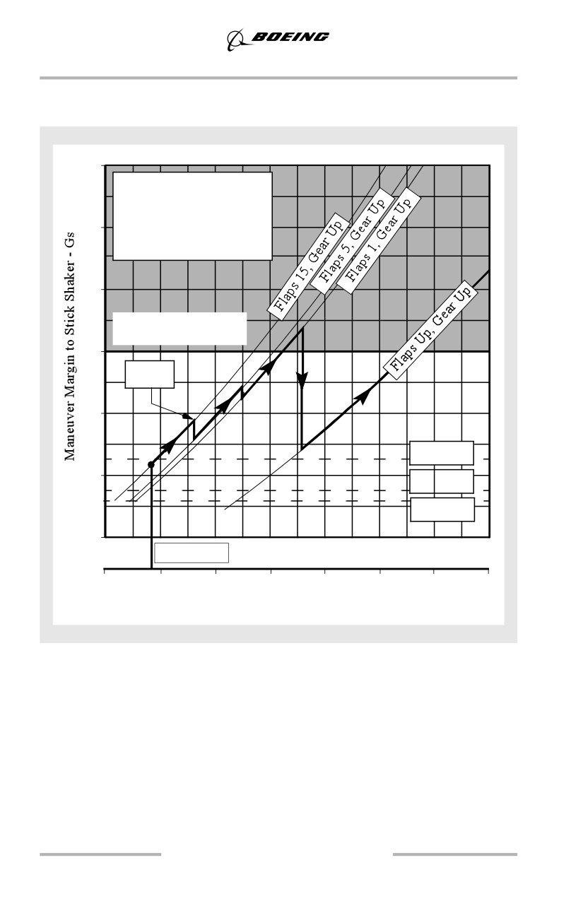
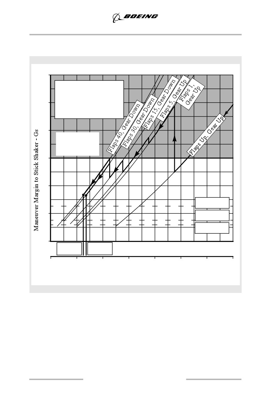
The following figures illustrate airplane maneuvering capability or margin to stick
shaker as a function of airspeed. This includes an engine inoperative departure
scenario (Takeoff) and an all engine approach scenario (Landing).
When reviewing the maneuver margin illustrations, note that:
• there is a direct correlation between bank angle and load factor (G's) in
level, constant speed flight. For example, 1.1G corresponds to 25° of
bank, 1.3G ~ 40°, 2.0G's ~ 60°
• the illustrated bank maneuver capability assumes a constant speed, level
flight condition
• stick shaker activates prior to actual stall speed
• the bold line designates flap configuration changes at the scheduled flap
transition speeds
• maneuver margins are based upon basic stick shaker schedules and do not
include adjustments for the use of anti-ice.
The distance between the bold line representing the flap retraction (Takeoff) or
extension schedule (Landing) and a given bank angle represents the maneuver
margin between stick shaker and the flap schedule for level constant speed flight.
Where the flap extension/retraction schedule extends below a depicted bank
angle, stick shaker activation can be expected prior to reaching that bank angle.
The takeoff figures assume a single engine climbout and takes into account the
vertical component of the thrust vector of one engine at full power. These figures
are an example of a heavy weight, sea level standard day condition. The unshaded
region of the chart represents the area within the certified structural load factor for
flaps down operation.
Note: The Maneuver Margins to Stick Shaker figures are to be used for training
purposes only. This data is not suitable for engineering analysis.
1.5
General Information
Maneuver Margins to Stick Shaker Takeoff
737-600
3.2
Weight = 143,500 Lbs
65,090 Kgs
One Engine Inoperative
2.8
Sea Level
Standard Day
2.4
Max Structural Load
Factor, Flaps Down
2.0
V2+15
1.6
40° Bank
1.2
25° Bank
15° Bank
0.8
V2 (flaps 15)
120
140
160
180
200
220
240
260
Airspeed (KCAS)
1.6
General Information
Maneuver Margins to Stick Shaker Landing
737-600
3.2
Weight = 120,500 Lbs
54,658 Kgs
All Engine
2.8
Sea Level
Standard Day
2.4
Max. Structural
Load Factor
Flaps Down
2.0
1.6
40° Bank
1.2
25° Bank
15° Bank
0.8
V
V
REF40
REF30
100
120
140
160
180
200
220
240
Airspeed (KCAS)
1.7
///////////////////////////////////////