Boeing 737 - 600/700/800/900. Flight Crew Training Manual (1999 year) - page 2
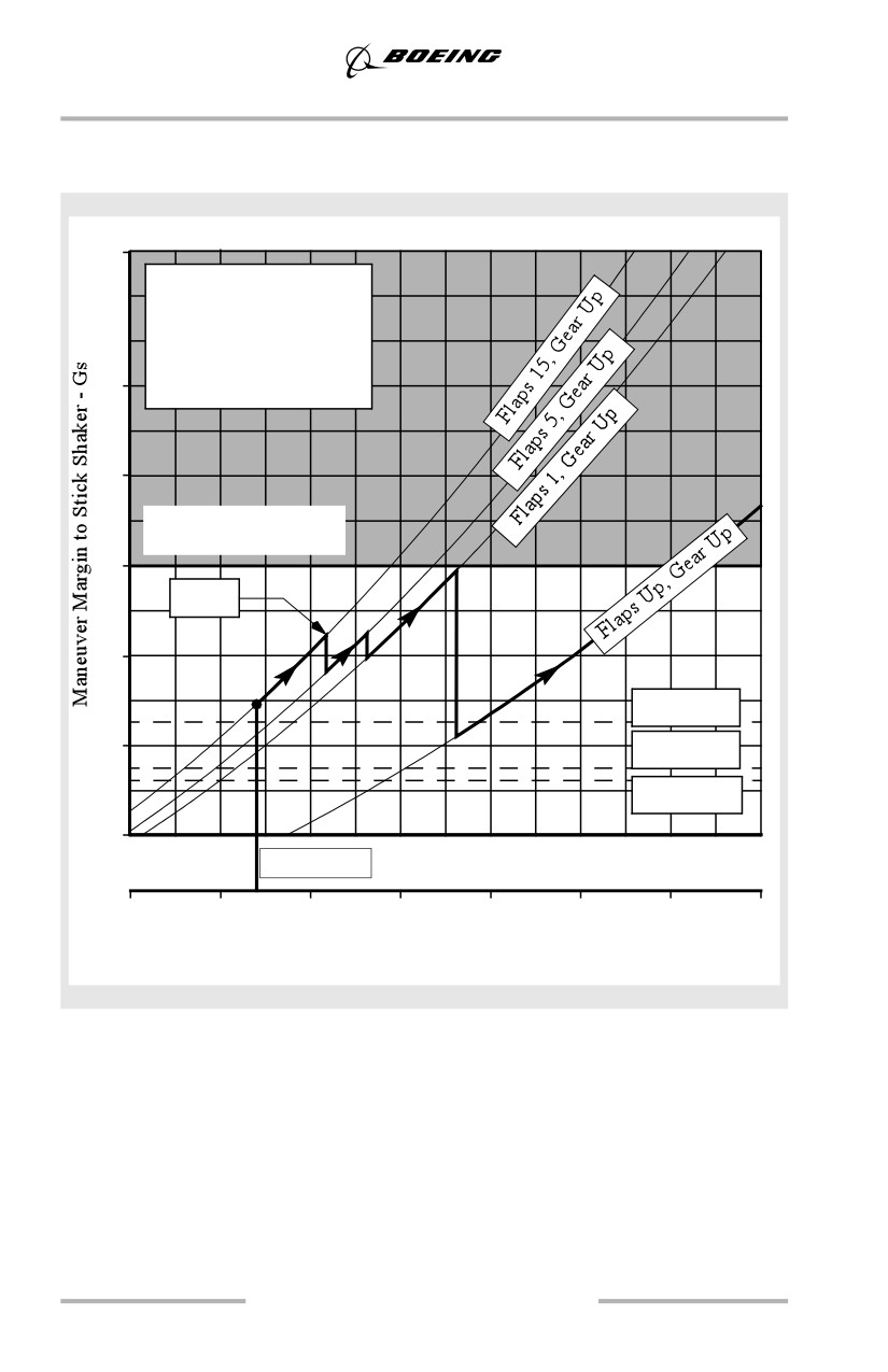
General Information
Maneuver Margins to Stick Shaker Takeoff
737-700
3.2
Weight = 154,500 Lbs
70,100 Kgs
One Engine Inoperative
Sea Level
2.8
Standard Day
2.4
Max Structural Load
Factor, Flaps Down
2.0
V
+15
2
1.6
40° Bank
1.2
25° Bank
15° Bank
0.8
V2 (flaps 15)
120
140
160
180
200
220
240
260
Airspeed (KCAS)
1.8
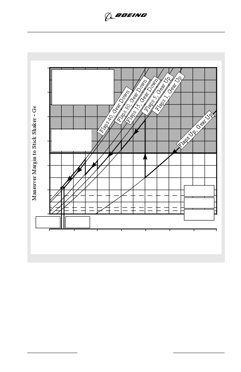
General Information
Maneuver Margins to Stick Shaker Landing
737-700
3.4
Weight = 129,200 Lbs
58,600 Kgs
All Engine
3.0
Sea Level
Standard Day
2.6
Max. Structural
2.2
Load Factor,
Flaps Down
1.8
1.4
40° Bank
25° Bank
1.0
15° Bank
V
V
REF40
REF30
120
140
160
180
200
220
240
260
Airspeed (KCAS)
1.9
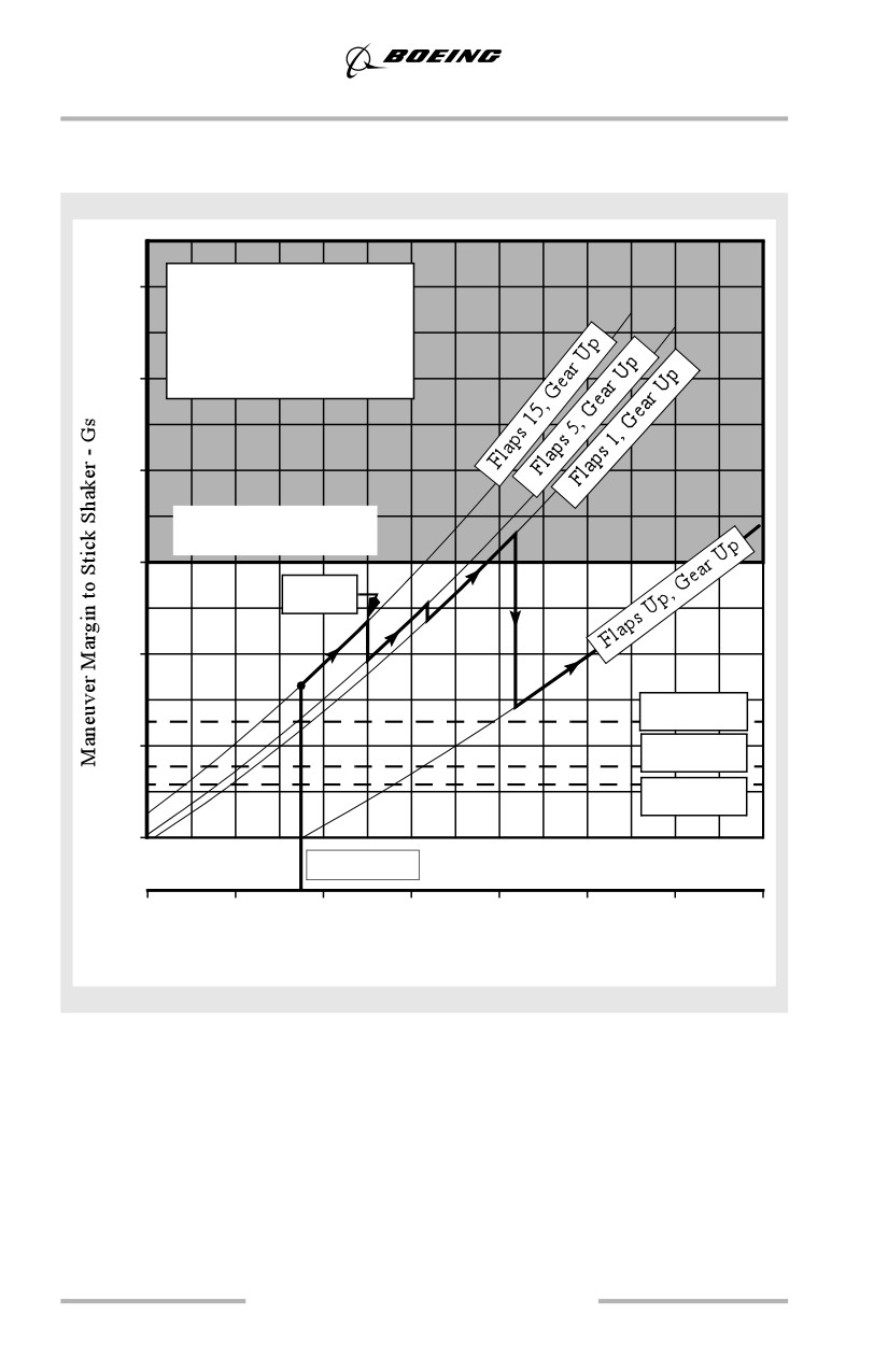
General Information
Maneuver Margins to Stick Shaker Takeoff
737-800
3.2
Weight = 174,200 Lbs
79,016 Kgs
One Engine Inoperative
Sea Level
2.8
Standard Day
2.4
Max Structural Load
Factor, Flaps Down
2.0
V
+15
2
1.6
40° Bank
1.2
25° Bank
15° Bank
0.8
V2 (flaps 15)
120
140
160
180
200
220
240
260
Airspeed (KCAS)
1.10
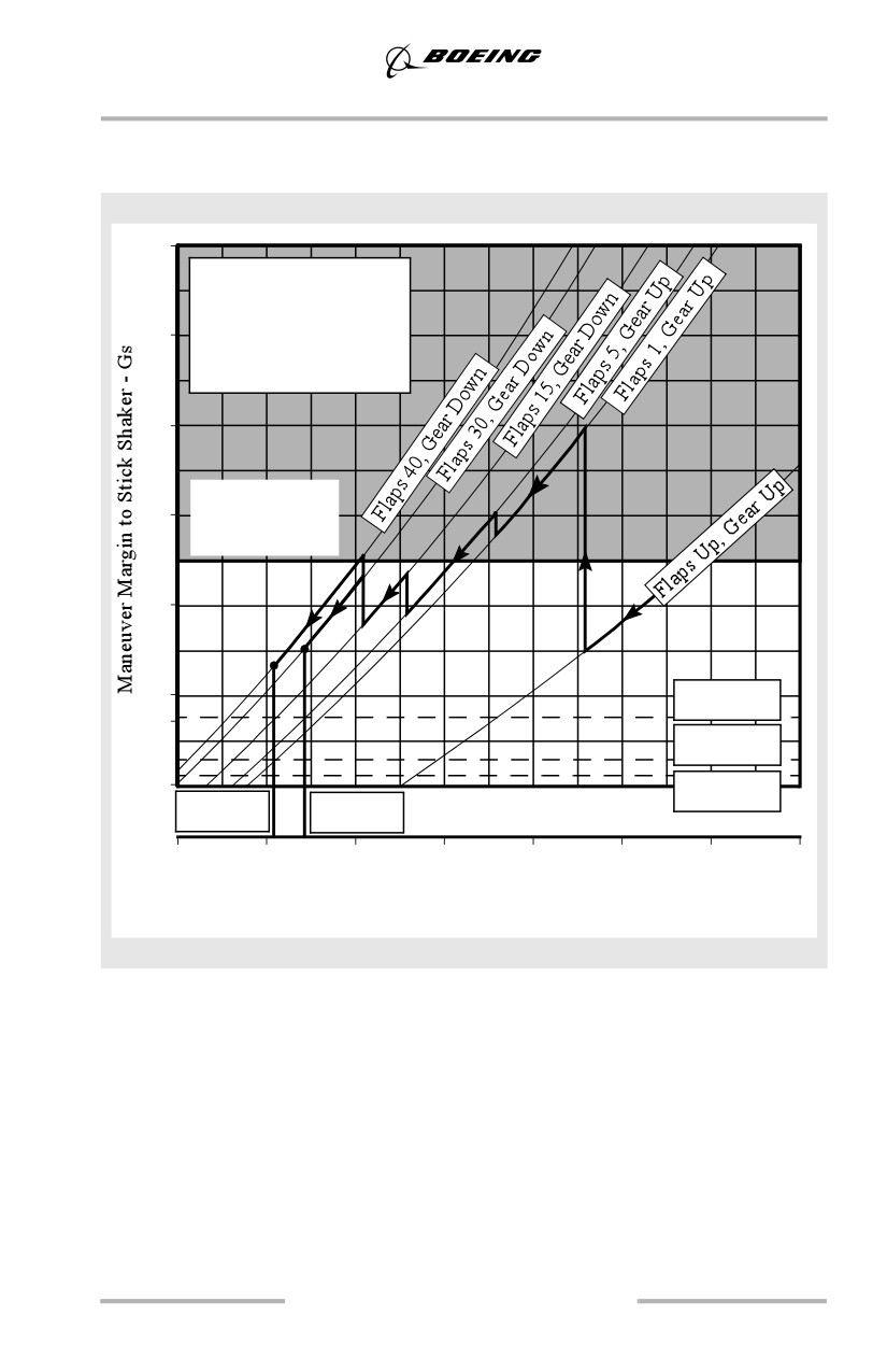
General Information
Maneuver Margins to Stick Shaker Landing
737-800
3.4
Weight = 146,300 Lbs
66,360 Kgs
All Engines
3.0
Sea Level
Standard Day
2.6
Max. Structural
2.2
Load Factor,
Flaps Down
1.8
1.4
40° Bank
25° Bank
1.0
15° Bank
V
VREF40
REF30
120
140
160
180
200
220
240
260
Airspeed (KCAS)
1.11
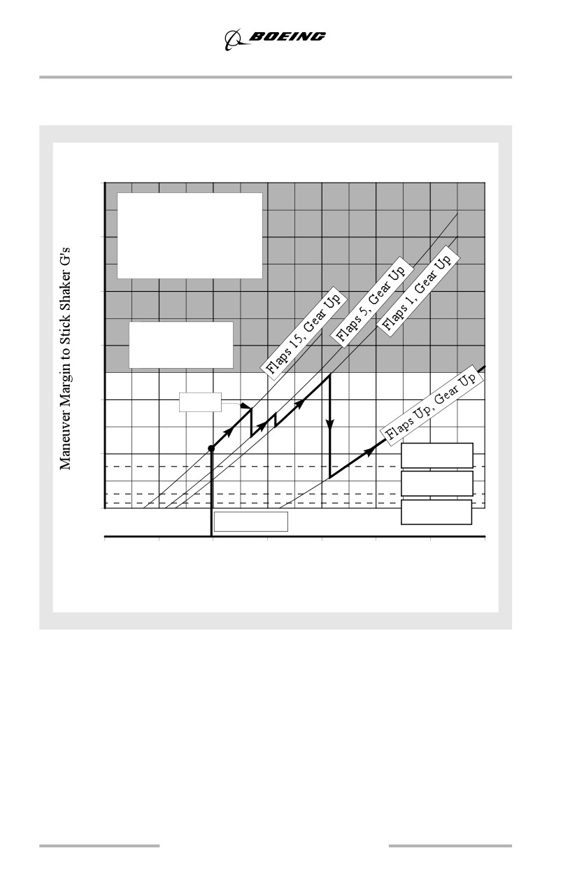
General Information
Maneuver Margins to Stick Shaker Takeoff
737-900
3.4
Weight=174,200 Lbs
79,016 Kgs
3.0
One Engine Inoperative
Sea Level
Standard Day
2.6
Max. Structural
2.2
Load Factor,
Flaps Down
1.8
V2+15
1.4
40° Bank
25° Bank
1.0
15° Bank
V2 (flaps 15)
120
140
160
180
200
220
240
260
Airspeed (KCAS)
1.12
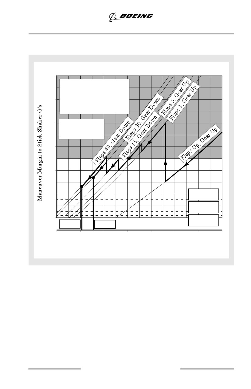
General Information
Maneuver Margins to Stick Shaker Landing
737-900
3.4
Weight=147,300 Lbs
66,815 Kgs
All Engines Operating
3.0
Sea Level
Standard Day
2.6
Max. Structural
Load Factor,
Flaps Down
2.2
1.8
1.4
40° Bank
25° Bank
1.0
15° Bank
VREF40
VREF30
120
140
160
180
200
220
240
260
Airspeed (KCAS)
1.13
General Information
Flap Operation
Acceleration Height - All Engines
The altitude selected for acceleration and flap retraction may be specified for each
airport. Safety, obstruction clearance, airplane performance or noise abatement
requirements are usually the determining factors. Some operators have adopted a
standard climb profile for all of their operations based on the airport which
requires the greatest height for level off to clear a close-in obstacle with an engine
failure.
The minimum altitude for flap retraction is 400 feet. Boeing recommends 1000
feet for the standard flap retraction altitude used in training.
Acceleration Height - Engine Out
Acceleration height for a takeoff with an engine failure after V1 is based on
accelerating to the recommended flaps up speed while retracting flaps and
selecting maximum continuous thrust limits within 5 minutes (10 minutes
optional) after initiating takeoff. Some combinations of high gross weight, takeoff
flap selection and airport elevation may require initiating flap retraction as low as
400 feet after takeoff with an engine failure.
At typical training weights, adequate performance exists to climb to 1000 feet
before beginning flap retraction. Therefore, during training, 1000 feet is used as
the acceleration height for engine failure after V1.
1.14
General Information
Command Speed
Command speed may be set by the pilot through the MCP or FMC and is
displayed by a magenta airspeed cursor on the airspeed indicator or by a magenta
speed bug on the PFD airspeed display.
Takeoff
Command speed remains set at V2 until changed by the pilot for acceleration and
flap retraction. Manually select flaps up maneuver speed at flap retraction altitude.
Climb, Cruise and Descent
Command speed is set to the appropriate speed by the FMC during VNAV
operation or manually using the MCP. The white airspeed bugs (if installed) are
positioned to the appropriate airspeeds for approach and landing.
Approach
Command speed is set to the maneuvering speed for the selected flap position by
the FMC during VNAV operation or manually using the MCP.
Landing
When using the autothrottle, position command speed to VREF + 5 knots.
Sufficient wind and gust protection is available with the autothrottle engaged
because the autothrottle is designed to adjust thrust rapidly when the airspeed
drops below command speed while reducing thrust slowly when the airspeed
exceeds command speed. In turbulence, the result is that average thrust is higher
than necessary to maintain command speed. This results in an average speed
exceeding command speed.
If the autothrottle is disengaged, or is planned to be disengaged prior to landing,
the recommended method for approach speed correction is to add one half of the
reported steady headwind component plus the full gust increment above the steady
wind to the reference speed. One half of the reported steady headwind component
can be estimated by using 50% for a direct headwind, 35% for a 45° crosswind,
zero for a direct crosswind and interpolation in between.
When making adjustments for wind additives, the maximum command speed
should not exceed VREF + 20 knots or landing flap placard speed minus 5 knots,
whichever is lower. This technique provides sufficient low speed maneuver
margin and reduces the possibility of flap load relief activation. Margin to load
relief activation may also be increased by using a reduced landing flap setting. The
following table shows examples of wind additives with a runway heading of 360°.
1.15

General Information
Reported Winds
Wind Additive
Approach Speed
360 at 16
8
VREF + 8 knots
Calm
0
VREF + 5 knots
360 at 20 Gust 30
10 + 10
VREF + 20 knots*
060 at 24
6
VREF + 6 knots
090 at 15
0
VREF + 5 knots
090 at 15 Gust 25
0 + 10
VREF + 10 knots
* If VREF + 20 exceeds landing flap placard speed minus 5 knots, use landing flap
placard speed minus 5 knots.
The minimum command speed setting with autothrottle disconnected is VREF +
5 knots. The gust correction should be maintained to touchdown while the steady
headwind correction should be bled off as the airplane approaches touchdown.
Note: Do not apply wind corrections for tailwinds. Set command speed at VREF
+ 5 knots (autothrottle engaged or disconnected).
Non-Normal Conditions
Occasionally, a non-normal checklist instructs the flight crew to use a VREF
speed that also includes a speed additive such as VREF 15 + 15. When VREF has
been adjusted by the non-normal procedure, the new VREF is called the adjusted
VREF and becomes the new VREF for landing (adjusted VREF does not include
wind corrections). For example, if a non-normal checklist specifies “Use flaps 15
and VREF 15 + 10 for landing”, the flight crew would select flaps 15 as the
landing flaps and look up the VREF 15 speed in the FMC or QRH and add 10
knots to that speed.
If the autothrottle is disengaged, or is planned to be disengaged prior to landing,
appropriate wind corrections must be added to the adjusted VREF to arrive at
command speed, the speed used to fly the approach. For example, if the checklist
states “use VREF 40 + 30 knots”, command speed should be positioned to
adjusted VREF (VREF 40 + 30) + wind correction (5 knots minimum, 20 knots
maximum).
If a flaps 15 landing is performed and VREF ICE is required, (VREF ICE = VREF
15 + 10), the wind correction should not exceed 10 knots.
1.16
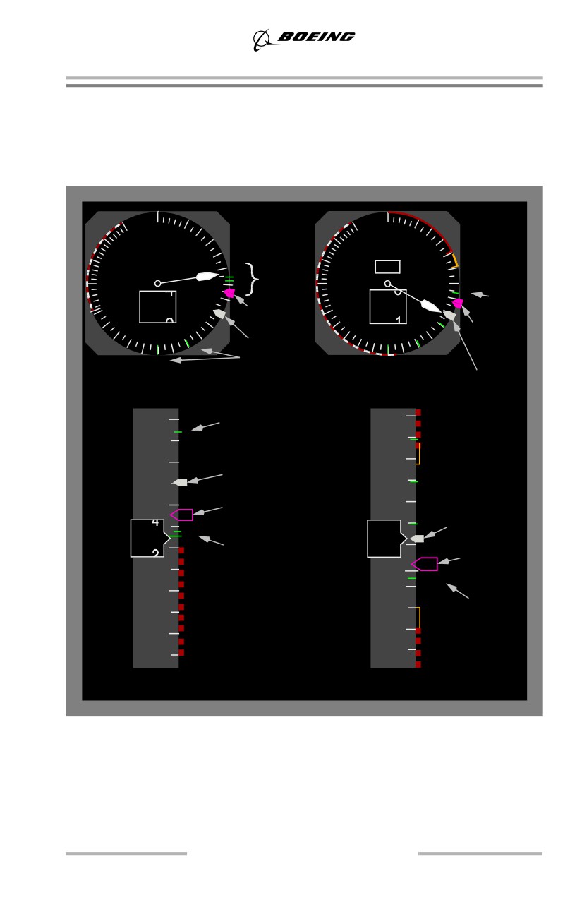
General Information
Reference Bugs
The following figure shows the positioning of the reference bugs on the airspeed
indicator for takeoff and approach.
Bug Setting (MASI or PFD/ND)
60
60
80
80
400
100
400
100
350
350
120
1
120
V
&
V
300
R
1
R
300
140
140
R
VREF
250
123
Command
250
152
240
160
Speed (V2 )
240
160
5
Command
220
180
220
180
200
V2
+ 15
200
Speed
1
1
UP
Flap
UP
Maneuvering
V
+ 15 *
REF
Takeoff
Speeds
Landing
180
Flap Maneuvering
210
1
Speed
UP
160
190
V2
+ 15
1
170
140
Command Speed (V
)
2
5
V
+ 15 *
3
REF
V1VR
123
1
V
&V
1
R
52
Command
Speed
REF
100
130
VREF
80
110
Takeoff
Landing
737-800, 737-900
* VREF + 20 with CDS Block Point 2004 and later. Refer to the FCOM for correct
configuration.
1.17
General Information
Takeoff
When V1, VR and gross weight are entered into the FMC, airspeed bugs are
automatically displayed at V1, VR and the minimum flap retraction speed for the
next flap position. Command speed is set at V2 using the MCP. V2 is the minimum
takeoff safety speed and provides at least 30° bank capability (15° + 15°
overshoot) for all takeoff flaps. An airspeed bug is automatically set 15 knots
above command speed. V2 + 15 provides 40° bank capability (25° + 15°
overshoot) for all takeoff flaps.
Approach - Landing
737-600, 737-700
VREF and VREF + 15 are displayed upon entry of landing flaps/speed in the
FMC. The maneuvering speed for the current flap position and the next flap
position are automatically displayed on the airspeed display.
737-800, 737-900
VREF and VREF + 15 (VREF + 20 for airplanes with CDS Block Point 2004 and
later) are displayed upon entry of landing flaps/speed in the FMC. The
maneuvering speed for the current flap position and the next flap position are
automatically displayed on the airspeed display.
Bug Setting with FMC Inoperative
With FMC inoperative, the speed reference selector is used to set V1, VR and
VREF. Refer to the FCOM, Section SP.10, for details.
1.18
General Information
Callouts
Both crewmembers should be aware of altitude, airplane position and situation.
Avoid nonessential conversation during critical phases of flight, particularly
during taxi, takeoff, approach and landing. Unnecessary conversation reduces
crew efficiency and alertness and is not recommended when below 10,000 feet
MSL / FL100. At high altitude airports, adjust this altitude upward, as required.
The Pilot Monitoring (PM) makes callouts based on instrument indications or
observations for the appropriate condition. The Pilot Flying (PF) should verify the
condition/location from the flight instruments and acknowledge. If the PM does
not make the required callout, the PF should make it.
The PM calls out significant deviations from command airspeed or flight path.
Either pilot should call out any abnormal indications of the flight instruments
(flags, loss of deviation pointers, etc.).
One of the basic fundamentals of Crew Resource Management is that each
crewmember must be able to supplement or act as a back-up for the other
crewmember. Proper adherence to standard callouts is an essential element of a
well-managed flight deck. These callouts provide both crewmembers required
information about airplane systems and about the participation of the other
crewmember. The absence of a standard callout at the appropriate time may
indicate a malfunction of an airplane system or indication, or indicate the
possibility of incapacitation of the other pilot.
The PF should acknowledge all GPWS voice callouts during approach except
altitude callouts while below 500 feet AFE. The standard callout of "CONTINUE"
or "GO-AROUND" at minimums is not considered an altitude callout and should
always be made. If the automatic electronic voice callout is not heard by the flight
crew, the PM should make the callout.
Note: If automatic callouts are not available, the PM may call out radio altitude
at 100 feet, 50 feet and 30 feet (or other values as required) to aid in
developing an awareness of eye height at touchdown.
1.19

General Information
Standard Callouts
CONDITION / LOCATION
CALLOUT
(Pilot Monitoring, unless noted)
Approaching Transition
“TRANSITION ALTITUDE/
Climb
Altitude/Transition Level
LEVEL, ALTIMETERS RESET
And
______” (in. or mb)
Descent
1000 ft. above/below assigned
“1000 FT TO LEVEL OFF”
altitude/Flight Level (IFR)
Descent
10,000 ft. MSL / FL100 (Reduce
“10,000 / FL100”
airspeed if required) (IFR and VFR)
1.20

General Information
Standard Callouts - ILS Approach
CONDITION / LOCATION
CALLOUT
(Pilot Monitoring, unless noted)
First positive inward motion of localizer pointer
“LOCALIZER ALIVE”
First positive motion of Glide Slope pointer
“GLIDE SLOPE ALIVE”
Final approach fix inbound
“OUTER MARKER/FIX, ____FT”
500 ft. AFE (Check autoland status
“500 FEET” (F/D or single autopilot
annunciator, if applicable)
approach)
Autoland status “FLARE ARMED”
(Autoland callout only)
Autoland status “LAND 2 or LAND
3 or NO AUTOLAND”
100 ft. above DA(H) (fail passive airplanes)
“APPROACHING MINIMUMS”
Individual sequence flasher lights visible
“STROBE LIGHTS”
At AH (fail operational airplanes) - check
“ALERT HEIGHT”
autoland status annunciator
At DA(H) with individual approach light bars
“MINIMUMS - APPROACH
visible
LIGHTS / RED BARS” (if installed)
At DA(H) - Suitable visual reference
PF: “CONTINUE”
established, i.e., PM calls visual cues
At DA(H) - Suitable visual reference not
PF: “GO AROUND”
established, i.e., PM does not call any visual
cues or only strobe lights
At minimums callout - If no response from PF
“I HAVE CONTROL______”
(state intentions)
Below DA(H) - Suitable visual reference
“THRESHOLD/RUNWAY
established
TOUCHDOWN ZONE”
Below DA(H) - Suitable visual reference
PF: “LANDING”
established
Below DA(H) - Suitable visual reference not
PF: “GO AROUND”
established, i.e., PM does not call any visual
cues
1.21

General Information
Standard Callouts - Non-ILS Approach
CONDITION / LOCATION
CALLOUT
(Pilot Monitoring, unless noted)
First positive inward motion of VOR or LOC
“COURSE/LOCALIZER ALIVE”
course deviation indication
Final approach fix inbound
“VOR/NDB/FIX”
500 ft. AFE
“500 FEET”
100 ft. above DA(H) or MDA(H)
“APPROACHING MINIMUMS”
Individual sequence flasher lights visible
“STROBE LIGHTS”
At DA(H) or MDA(H) with individual
“MINIMUMS - APPROACH
approach light bars visible
LIGHTS / RED BARS” (if installed)
At DA(H) or MDA(H) - Suitable visual
PF: “CONTINUE”
reference established, i.e., PM calls visual cues
At DA(H) or MDA(H)- Suitable visual
PF: “GO AROUND”
reference not established, i.e., PM does not call
any visual cues or only strobe lights
At minimums callout - If no response from PF
“I HAVE CONTROL______”
(state intentions)
Below DA(H) or MDA(H)- Suitable visual
“THRESHOLD/RUNWAY
reference established
TOUCHDOWN ZONE”
Below DA(H) or MDA(H)- Suitable visual
PF: “LANDING”
reference established
Below DA (H) or MDA(H)- Suitable visual
PF: “GO AROUND”
reference not established, i.e., PM does not call
any visual cues
1.22
General Information
Standard Phraseology
A partial list of recommended words and phrases follows:
Thrust:
•
“SET TAKEOFF THRUST”
•
“SET GO-AROUND THRUST”
•
“SET MAXIMUM CONTINUOUS THRUST”
•
“SET CLIMB THRUST”
•
“SET CRUISE THRUST”
Flap Settings:
•
“FLAPS UP”
•
“FLAPS ONE”
•
“FLAPS FIVE”
•
“FLAPS TEN”
•
“FLAPS FIFTEEN”
•
“FLAPS TWENTY-FIVE”
•
“FLAPS THIRTY”
•
“FLAPS FORTY”
Airspeed:
•
“80 KNOTS”
•
“V1”
•
“ROTATE”
•
“SET _____ KNOTS”
•
“SET VREF PLUS (additive)”
•
“SET FLAPS _____ SPEED”
1.23
General Information
Electronic Flight Bag (EFB)
This section provides guidance on the use of the optional Electronic Flight Bag
(EFB).
Airport Moving Map
The airport map display is intended to enhance crew positional awareness while
planning taxi routes and while taxiing. The system is not intended to replace
normal taxi methods including the use of direct visual observation of the taxiways,
runways, airport signs and markings and other airport traffic. Prior to taxi,
NOTAMS and airport charts (using EFB terminal charts or paper) should be
consulted for the latest airport status to include closed taxiways, runways,
construction, etc., since these temporary conditions are not shown on the airport
map.
Note: Crews must avoid fixation on the display or distraction from primary crew
duties while using any EFB application.
Crews must use direct visual observation out flight deck windows as the primary
taxi navigation reference. Use the airport Heading-Up or North-Up map to provide
enhanced positional awareness by:
• verifying taxi clearance and assisting in determining taxi plan (both
pilots)
• monitoring taxi progress and direction (both pilots)
• alerting and updating the pilot taxiing with present position and upcoming
turns and required stops (pilot not taxiing).
In flight, the airport North-Up (fixed) fixed map may be used to aid in runway exit
planning and anticipating the taxi route to the gate or parking spot.
If one airport map display is inoperative at dispatch, the crewmember with the
inoperative display may wish to keep a paper copy of the airport diagram readily
available. During taxi in this situation, one pilot should continue to use the airport
map display for positional awareness while the other pilot monitors progress on
the paper chart. If an airport map display fails after dispatch and no paper backup
airport diagrams are available, the crew should consider having the pilot not
taxiing provide progressive taxi and positional updates to the pilot taxiing or
request progressive taxi instruction from ground control. In any case, the pilot
taxiing should always devote primary attention to taxiing the airplane by external
visual observation. If the airport map display is inoperative on both sides, use
normal taxi procedures.
Note: GPS position must be available to use the Heading-Up map.
1.24
General Information
Terminal Charts
Electronic terminal charts may be used in place of paper charts. Enroute charts are
not available in the EFB at this time. Should the airplane dispatch with one or both
displays inoperative, the crew should comply with the provisions of the MEL
regarding the use of backup charts.
Airplane Performance
When all appropriate entries are made, the airplane performance application
provides runway specific performance information equivalent to AFM-DPI data
or airline airport analysis. During approach preparation, the system can provide
advisory landing distance information.
Video Surveillance
The video surveillance display may be used at the discretion of the crew to identify
individuals requesting flight deck entry or for other airline-specific purposes such
as passenger cabin or cargo compartment observation.
Electronic Logbook and Other Documents
The electronic logbook and other electronic documents should be used as defined
by operator policy and procedures.
Flight Path Vector (FPV)
The FPV displays Flight Path Angle (FPA) relative to the horizon line and drift
angle relative to the center of the pitch scale on the attitude display. This indication
uses inertial and barometric altitude inputs. The vertical flight path angle
displayed by the FPV should be considered unreliable with unreliable primary
altitude displays. The FPV can be used by the pilot in several ways:
• as a reference for establishing and maintaining level flight when the F/D
is not in use or not available. When maneuvering the airplane, adjust pitch
to place the FPV on the horizon. This results in zero vertical velocity
• as a cross-check of the vertical flight path angle when established in a
climb, descent, or on a visual final approach segment
Note: When on final approach, the FPV does not indicate airplane glide path
relative to the runway. ILS glide slope, VASI/PAPI or other means must
be used for a proper glide path indication.
• in climbs or descents, radar tilt can be adjusted to an appropriate elevation
based on the displayed FPA. Radar tilt, like the FPV, is referenced to the
horizon. Example: Adjusting the radar tilt to the same angle relative to the
horizon as the FPV during climb results in the radar beam centered on the
existing flight path
1.25
General Information
• as a qualitative indication of airplane lateral drift direction if the map is
not available. The FPV moves left or right of the pitch scale to indicate
the relative position of the ground track to the present heading. The
amount of drift cannot be determined from this display unless the airplane
is equipped with heading marks on the horizon line. Example: FPV
displaced to the left indicates wind component from the right and
corresponding drift to the left
• as a reference by the pilot in maintaining proper pitch control with
unreliable airspeed indications. Adjust pitch to establish desired flight
path by placing the FPV just above, below or on the horizon line.
Note: The FPV should not be used in reference to the PLI, which is a pitch
attitude referenced display.
Cold Temperature Altitude Corrections
If the outside air temperature (OAT) is different from standard atmospheric
temperature (ISA), barometric altimeter errors result due to non-standard air
density. Larger temperature differences from standard result in larger altimeter
errors. When the temperature is warmer than ISA, true altitude is higher than
indicated altitude. When the temperature is colder than ISA, true altitude is lower
than indicated altitude. Extremely low temperatures create significant altimeter
errors and greater potential for reduced terrain clearance. These errors increase
with higher airplane altitudes above the altimeter source.
Generally, operators should consider altitude corrections when altimeter errors
become appreciable, especially where high terrain and/or obstacles exist near
airports in combination with very cold temperatures (-30°C/ -22°F or colder).
Further, operators should also consider correcting en route minimum altitudes
and/or flight levels where terrain clearance is a factor. In some cases corrections
may be appropriate for temperatures between 0°C and -30°C.
Operators should coordinate with local and en route air traffic control facilities for
each cold weather airport or route in their system. Coordination should include:
• confirmation that minimum assigned altitudes or flight levels provide
adequate terrain clearance for the coldest expected temperatures
• cold weather altitude correction procedures to be used for published
procedures, to include the table being used
• a determination of which procedures or routes, if any, that have been
designed for cold temperatures and can be flown as published (without
altitude corrections).
Pilots should note that for very cold temperatures, when flying published
minimum altitudes significantly above the airport, altimeter errors can exceed
1000 feet, resulting in potentially unsafe terrain clearance if no corrections are
made.
1.26
General Information
Operation in Icing Conditions
Boeing airplanes are certified to all applicable airworthiness regulations regarding
flight in icing conditions. Operators are required to observe all operational
procedures concerning flight in these conditions.
Although the process of certifying jet transport airplanes for operation in icing
conditions involves many conservative practices, these practices have never been
intended to validate operations of unlimited duration in severe icing conditions.
The safest course of action is to avoid prolonged operation in moderate to severe
icing conditions.
Training Flights
Multiple approaches and/or touch and go landings in icing conditions may result
in significant ice accumulations beyond those experienced during typical revenue
flights. This may result in fan blade damage as a result of ice accumulation on
unheated surfaces shedding into the engines.
1.27
General Information
Recommended Rudder Trim Technique
This section describes two techniques for properly trimming the rudder. It is
assumed that the airplane is properly rigged and in normal cruise. The primary
technique uses rudder trim only to level the control wheel and is an acceptable and
effective method for trimming the airplane. It is approximately equal to a
minimum drag condition. This technique is usable for normal as well as many
non-normal conditions. For some non-normal conditions, such as engine failure,
this technique is the preferred method and provides near minimum drag.
The alternate technique may provide a more accurate trim condition when the roll
is caused by a roll imbalance. In addition, this technique outlines the steps to be
taken if the primary trim technique results in an unacceptable bank angle or
excessive rudder trim. The alternate technique uses both rudder and aileron trim
to neutralize a rolling condition using the bank pointer as reference.
Note: Large trim requirements should be documented for maintenance. Refer to
the maintenance manual for guidance.
Drag Factors Due to Trim Technique
If the control wheel is displaced to the point of spoiler deflection a significant
increase in aerodynamic drag results. Additionally, any rigging deviation that
results in early spoiler actuation causes a significant increase in drag per unit of
trim. These conditions result in increased fuel consumption. Small out of trim
conditions affect fuel flow by less than 1%, if no spoilers are deflected.
Note: Aileron trim may be required for significant fuel imbalance, airplane
damage, or flight control system malfunctions.
Primary Rudder Trim Technique
It is recommended that the autopilot remain engaged while accomplishing the
primary rudder trim technique (using rudder trim only). After completing this
technique, if the autopilot is disconnected, the airplane should maintain a constant
heading.
The following steps define the primary rudder trim technique:
• set symmetrical thrust
• balance fuel if required
1.28
General Information
• ensure the autopilot is engaged in HDG SEL and stabilized for at least 30
seconds
• trim the rudder in the direction corresponding to the down (low) side of
the control wheel until the control wheel indicates level. The indices on
top of the control wheel should be used to ensure a level wheel condition.
The airplane is properly trimmed when the control wheel is level, (zero
index). As speed, gross weight, or altitude change, trim requirements may
also change. In a proper trim condition, there may be a slight forward slip
(slight bank angle indicated on the bank pointer) and a slight deflection of
the slip/skid indicator, which is acceptable.
Alternate Rudder Trim Technique
The alternate rudder trim technique is used if the primary trim technique results in
an unacceptable bank angle, excessive rudder trim, or if a more accurate dual axis
trim is required.
The following steps define the alternate rudder trim technique:
• set symmetrical thrust
• balance fuel if required
• verify rudder trim is zero
• ensure the autopilot is engaged in HDG SEL and stabilized for at least 30
seconds
• trim the rudder in the direction corresponding to the down (low) side of
the control wheel until the bank indicates level (no bank angle indicated
on the bank pointer). Apply rudder trim incrementally, allowing the bank
to stabilize after each trim input. Large trim inputs are more difficult to
coordinate. The airplane is properly trimmed when the bank angle on the
bank pointer indicates zero. If the airplane is properly rigged, the control
wheel should indicate approximately level. The resultant control wheel
condition indicates the true aileron (roll) trim of the airplane being used
by the autopilot.
After completing the alternate rudder trim technique, if the autopilot is disengaged
the airplane may have a rolling tendency. Hold the wings level using the sky
pointer as reference. Trim out any control wheel forces using the aileron trim
switches. If properly trimmed, the airplane holds a constant heading and the
aileron trim reading on the wheel/column agrees with what was seen while the
autopilot was engaged. Aileron trim inputs require additional time and should be
accomplished prior to final approach.
1.29
General Information
Flight Management Computer(s)/CDUs
The Flight Management System provides the crew with navigation and
performance information that can result in a significant crew workload reduction.
This workload reduction is fully realized when the system is operated as intended,
including proper preflight and timely changes in flight. FMC guidance must
always be monitored after any in flight changes. If flight plan changes occur
during periods of high workload or in areas of high traffic density, the crew should
not hesitate to revert to modes other than LNAV/VNAV.
During preflight, all flight plan or performance related FMC CDU entries made
by one pilot must be verified by the other pilot. In flight FMC CDU changes
should be made by the PM and executed only after confirmation by the PF.
FMC Route Verification Techniques
After entering the route into the FMC, the crew should verify that the entered route
is correct. There are several techniques that may be used to accomplish this. The
crew should always compare:
• the filed flight plan with the airways and waypoints entered on the
ROUTE pages
• the computer flight plan total distance and estimated fuel remaining with
the FMC-calculated distance to destination and the calculated fuel
remaining at destination on the PROGRESS page.
For longer flights and flights that are planned to transit oceanic airspace, the crew
should cross-check each leg on the LEGS page with the computer flight plan to
ensure that the waypoints, magnetic or true tracks, and distances between
waypoints match.
If there is a discrepancy noted in any of the above, correct the LEGS page to match
the filed flight plan legs. A cross check of the map display using the plan mode
may also assist in verification of the flight plan.
FMC Performance Predictions - Non-Normal Configuration
FMC performance predictions are based on the airplane being in a normal
configuration. These predictions include:
• climb and descent path predictions including top of climb and top of
descent
• ECON, LRC, holding, and engine out speeds
• altitude capability
• step climb points
• fuel remaining at waypoints and destination or alternate
• estimated time of arrival at waypoints and destination or alternate
• holding time available.
1.30
General Information
If operating in a non-normal configuration, such as gear down, flaps extended,
spoilers extended, gear doors open, etc., these performance predictions are
inaccurate. FMC predictions for the climb and descent path are not usable.
Do not use FMC fuel predictions. Cruise fuel predictions are based on a clean
configuration. Fuel consumption may be significantly higher than predicted in
other configurations.
Note: VNAV PTH operation for approaches is usable for non-normal
configurations.
An accurate estimated time of arrival is available if current speed or Mach is
entered into the VNAV cruise page. Estimates of fuel remaining at waypoints or
the destination may be computed by the crew based upon current fuel flow
indications, but should be updated frequently. Performance information for gear
down altitude capability and gear down cruise performance is available in the PI
chapter of the QRH.
Holding time available is accurate only in the clean configuration provided the
FMC holding speed is maintained.
RNP and RNAV Operations
This section describes the basic concepts of RNP and provides information on
RNAV operations by phase of flight to include terminal (SIDs and STARs),
en-route, and approach.
Basic RNP Concept
RNP has been developed through international cooperation as a means of
identifying the navigation performance required for a specified area, route,
airspace, procedure or operation. RNP supports use of RNAV systems that use
multi-sensor position updating methods such as the flight management computer
(FMC). This accuracy is specified in NM (e.g., RNP 0.3 means the performance
required is “within 0.3 NM”). RNP values are usually smaller for terminal area
procedures (SIDs, STARs, approach transitions, and approaches) than en-route
procedures. Small RNP values normally require navigation performance that is
more precise than current VOR/ADF navigation, allowing lower weather minima
for departures and/or approaches.
1.31
General Information
The FMC uses one of the following as the displayed RNP:
• default RNP - FMC default values are set by the FMC and are displayed if
no RNP is available from the navigation data base or one has not been
manually entered
• navigation Data Base RNP - RNP values (if available) are displayed
based on values associated with the procedure. These values may be
unique for certain segments or terminal procedures
• manually entered RNP - remains until changed or deleted.
The crew may need to make a manual RNP entry if the displayed RNP for the
route or procedure is incorrect. Setting an RNP smaller than what is specified for
the procedure, airspace, or route, may cause nuisance crew alerts. If the RNP is
larger than required for a procedure or segment, inadequate alerting results if
needed. Operators should select FMC default values that meet the requirements of
their route structure or terminal area procedures. However, AFM requirements
may specify RNPs for certain approaches. (For example, RNP 0.3 is required for
RNAV (GPS) approaches).
The FMC calculates and displays its Actual Navigation Performance (ANP) as
described in the FCOM. When the ANP exceeds the RNP a crew alert is provided.
When this occurs on a route or terminal area procedure where an RNP is
published, the crew should verify position, confirm updating is enabled, and
consider requesting an alternate clearance. This may mean changing to a non-RNP
procedure or route or changing to a procedure or route with a RNP higher than the
displayed ANP value. Crews should note that ANP is only related to the accuracy
of FMC position. Lateral deviation from the route or procedural track is indicated
by the XTK ERROR (cross-track error) value shown by the FMC. LNAV should
be used with the autopilot engaged to minimize cross-track error. Excessive XTK
ERROR does not result in a crew alert.
Note: The NPS system (as installed) provides an alert on the PFD when lateral or
vertical deviation exceeds preset limits. Reference the FCOM for specific
NPS system indications and description.
The following illustration shows the FMC position and displayed ANP and shows
the relationship of ANP to RNP for a particular route segment. Normally, a route
segment or procedural leg is defined by its required width (the illustration shows
2.0 NM either side of the centerline). RNP is normally set at 50% of the allowed
maximum deviation from the route centerline. Required width is determined by
minimum terrain or traffic clearance requirements. The probability of exceeding
this maximum deviation while in LNAV with the autopilot engaged is very small.
For each airplane type, minimum demonstrated RNPs are given in the AFM.
These minimum values vary depending on LNAV, flight director and autopilot
use.
1.32
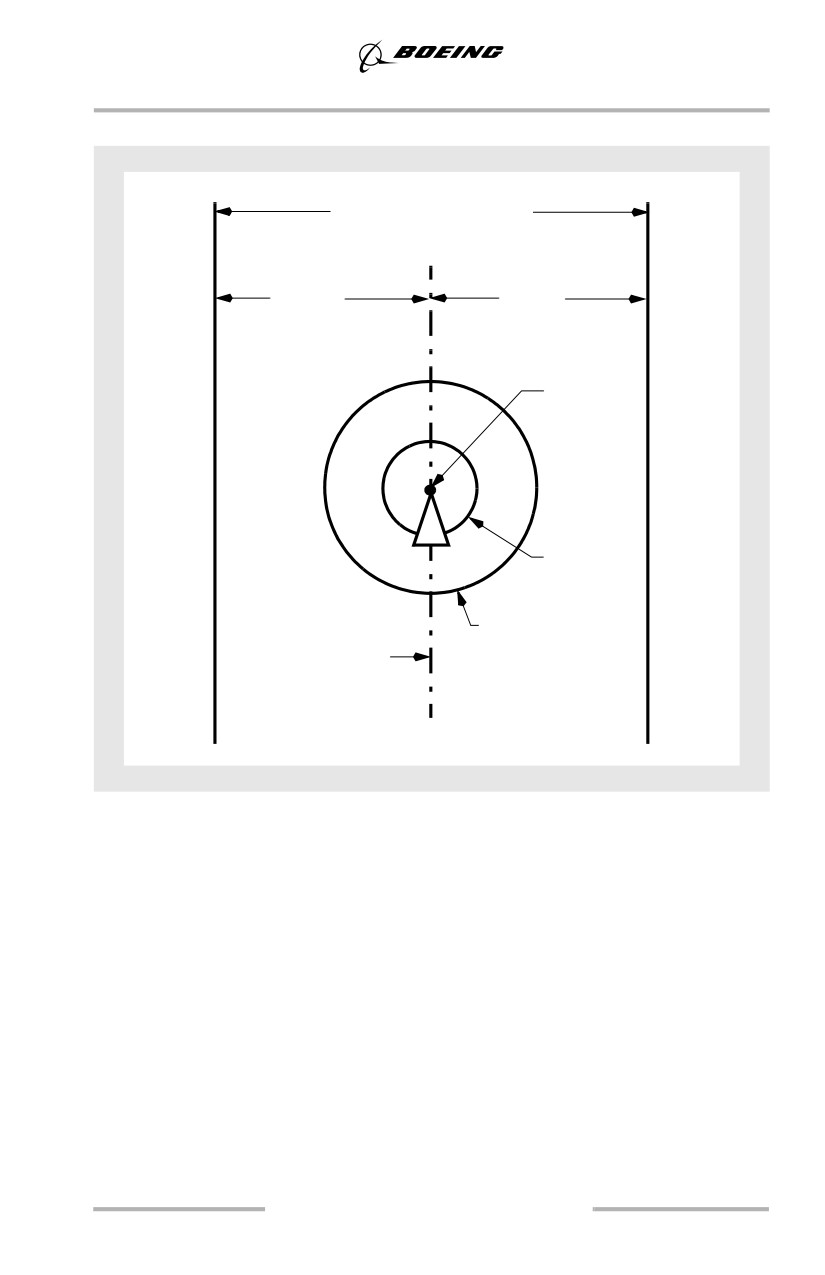
General Information
RNAV Route and RNP/ANP
Required Route Width
(4.0 NM example)
2.0 NM
2.0 NM
example
example
FMC
Position
ANP
RNP
(1.0 NM example)
Route or Procedure
Centerline
RNAV Operations: En-route, Terminal, and Approach
All Boeing FMCs are capable of performing RNAV operations. Regarding
navigation accuracy, these FMCs differ only by demonstrated RNP capabilities
and the ability to use GPS updating.
En-route operations can be defined as oceanic and domestic. Oceanic RNAV
requirements are described in detail in the applicable MNPS guidance material
such as the Pacific or North Atlantic manuals. Specific routes or areas of operation
are given RNPs based on route separation requirements. RNP 10 routes are
suitable for all FMCs that are capable of GPS updating and those FMCs that
cannot update from GPS but have received the last radio update within the
previous six hours.
In general, oceanic operations require dual navigation systems (dual FMC or
single FMC in combination with alternate navigation capability).
1.33
General Information
Domestic en-route RNAV operations depend on the availability of radio updating
(DME-DME) sources to support domestic RNPs. The following domestic RNP
operations are fully supported by any Boeing FMC with DME-DME or GPS
updating active:
• USA and Canada - RNP 2.0 or higher
• Europe - B-RNAV (RNP 5.0)
• Asia - As specified for the route or area (e.g. RNP 4 or RNP 10 routes)
• Africa - As specified for the route or area
Terminal RNAV operations (SIDs, STARs and Transitions) are fully compatible
with all FMCs with DME-DME or GPS updating active and are defined as:
• USA and Canada - RNP 1.0 SIDs and STARS
• Europe - P-RNAV (RNP 1.0)
RNAV approaches are compatible with all FMCs provided DME-DME or GPS
updating is active at the beginning of the approach and the approach RNP is equal
to or greater than the minimum demonstrated RNP in the AFM. Restrictions
published on some RNAV approaches may preclude their use without GPS
updating active.
For published RNAV approaches, all Boeing FMCs have RNP 0.5 capability with
DME-DME updating active without GPS updating. See the Approach section of
this manual for further details regarding the techniques for flying RNAV
approaches.
GPS Use in Non-WGS-84 Reference Datum Airspace
In non-WGS-84 airspace, the local datum (position basis) used to survey the
navigation data base position information may result in significant position errors
from a survey done using the WGS-84 datum. To the pilot, this means that the
position of runways, airports, waypoints, navaids, etc., may not be as accurate as
depicted on the map display and may not agree with the GPS position. Operators
should consult appropriate sources to determine the current status of airspace in
which they operate.
A worldwide survey has been conducted which determined that using the FMC
while receiving GPS position updating during SIDS, STARS and enroute
navigation meets the required navigation accuracy in non-WGS-84 airspace. This
navigation position accuracy may not be adequate for approaches, therefore the
AFM requires the crew to inhibit GPS position updating while flying approaches
in non-WGS-84 airspace “unless other appropriate procedures are used.”
1.34
General Information
Boeing's recommendations for operators are as follows:
• Provided operational approval has been received and measures to ensure
their accuracy have been taken, RNAV approaches may be flown with
GPS updating enabled. Options available to operators may include
surveys of the published approaches to determine if significant
differences or position errors exist, developing special RNAV procedures
complying with WGS-84 or equivalent, or inhibiting GPS updating
• For approaches based upon ground-based navigation aids such as ILS,
VOR, LOC, NDB, etc., the GPS updating need not be inhibited provided
that appropriate raw data is used throughout the approach and missed
approach as the primary navigation reference. LNAV and VNAV may be
used. As always, when a significant difference exists between the airplane
position, raw data course, DME and/or bearing information, discontinue
use of LNAV and VNAV. Provided the FMC is not used as the primary
means of navigation for approaches, this method can be used as the “other
appropriate procedure” in lieu of inhibiting GPS updating.
Operators are encouraged to survey their navigation data bases and have all
non-WGS-84 procedures eliminated or modified to WGS-84 standards.
Weather Radar and Terrain Display Policy
Whenever the possibility exists for adverse weather and terrain/obstacles near the
intended flight path, one pilot should monitor the weather radar display and the
other pilot should monitor the terrain display. The use of the terrain display during
night or IMC operations, on departure and approach when in proximity to
terrain/obstacles, and at all times in non-radar environments is recommended.
Note: It may be useful to show the terrain display at other times to enhance
terrain/situational awareness.
AFDS Guidelines
Crewmembers must coordinate their actions so that the airplane is operated safely
and efficiently.
Autopilot engagement should only be attempted when the airplane is in trim, F/D
commands (if the F/D is on) are essentially satisfied and the airplane flight path is
under control. The autopilot is not certified or designed to correct a significant out
of trim condition or to recover the airplane from an abnormal flight condition
and/or unusual attitude.
Autothrottle Use
Autothrottle use is recommended during takeoff and climb in either automatic or
manual flight. During all other phases of flight, autothrottle use is recommended
only when the autopilot is engaged.
1.35
General Information
Autothrottle ARM Mode
The autothrottle ARM mode is normally not recommended because its function
can be confusing. The primary feature the autothrottle ARM mode provides is
minimum speed protection in the event the airplane slows to minimum
maneuvering speed. Other features normally associated with the autothrottle, such
as gust protection, are not provided. The autothrottle ARM mode should not be
used with Non-Normal Checklists. Some malfunctions that affect maneuvering
speeds cause the autothrottle to maintain a speed above approach speed.
Manual Flight
The PM should make AFDS mode selections at the request of the PF. Heading and
altitude changes from ATC clearances and speed selections associated with flap
position changes may be made without specific directions. However, these
selections should be announced, such as, “HEADING 170 SET”. The PF must be
aware such changes are being made. This enhances overall safety by requiring that
both pilots are aware of all selections, while still allowing one pilot to concentrate
on flight path control.
Ensure the proper flight director modes are selected for the desired maneuver. If
the flight director commands are not to be followed, the flight director should be
turned off.
Automatic Flight
Autoflight systems can enhance operational capability, improve safety, and reduce
workload. Automatic approach and landing, Category III operations, and
fuel-efficient flight profiles are examples of some of the enhanced operational
capabilities provided by autoflight systems. Maximum and minimum speed
protection are among the features that can improve safety while LNAV, VNAV,
and instrument approaches using VNAV are some of the reduced workload
features. Varied levels of automation are available. The pilot decides what level of
automation to use to achieve these goals by selecting the level that provides the
best increase in safety and reduced workload.
Note: When the autopilot is in use, the PF makes AFDS mode selections. The PM
may select new altitudes, but must ensure the PF is aware of any changes.
Both pilots must monitor AFDS mode annunciations and the current FMC
flight plan.
1.36
General Information
Automatic systems give excellent results in the vast majority of situations.
Deviations from expected performance are normally due to an incomplete
understanding of their operations by the flight crew. When the automatic systems
do not perform as expected, the pilot should reduce the level of automation until
proper control of path and performance is achieved. For example, if the pilot failed
to select the exit holding feature when cleared for the approach, the airplane will
turn outbound in the holding pattern instead of initiating the approach. At this
point, the pilot may select HEADING SELECT and continue the approach while
using other automated features. A second example, if the airplane levels off
unexpectedly during climb or descent with VNAV engaged, LVL CHG may be
selected to continue the climb or descent until the FMC can be programmed.
Early intervention prevents unsatisfactory airplane performance or a degraded
flight path. Reducing the level of automation as far as manual flight may be
necessary to ensure proper control of the airplane is maintained. The pilot should
attempt to restore higher levels of automation only after airplane control is
assured. For example, if an immediate level-off in climb or descent is required, it
may not be possible to comply quickly enough using the AFDS. The PF should
disconnect the autopilot and level off the airplane manually at the desired altitude.
After level off, set the desired altitude in the MCP, select an appropriate pitch
mode and re-engage the autopilot.
Recommended Pitch and Roll Modes
If the LEGS page and map display reflect the proper sequence and altitudes,
LNAV and VNAV are recommended. If LNAV is not used, use an appropriate roll
mode. When VNAV is not used, the following modes are recommended:
LVL CHG is the preferred mode for altitude changes of 1,000 feet or more. V/S is
preferred if the altitude change is less than 1,000 feet.
If unplanned speed or altitude restrictions are imposed during the arrival, the
continued use of VNAV may induce an excessive workload. If this occurs, use
LVL CHG or V/S as appropriate.
Pilot Incapacitation
Pilot incapacitation occurs frequently compared with other routinely trained
non-normal conditions. It has occurred in all age groups and during all phases of
flight. Incapacitation occurs in many forms ranging from sudden death to subtle,
partial loss of mental or physical performance. Subtle incapacitations are the most
dangerous and they occur the most frequently. Incapacitation effects can range
from loss of function to unconsciousness or death.
1.37
General Information
The key to early recognition of pilot incapacitation is the regular use of crew
resource management concepts during flight deck operation. Proper crew
coordination involves checks and crosschecks using verbal communications.
Routine adherence to standard operating procedures and standard profiles can aid
in detecting a problem. Suspicion of some degree of gross or subtle incapacitation
should also be considered when a crewmember does not respond to any verbal
communication associated with a significant deviation from a standard procedure
or standard flight profile. Failure of any crewmember to respond to a second
request or a checklist response is cause for investigation.
If you do not feel well, let the other pilot know and let that pilot fly the airplane.
During flight, crewmembers should also be alert for incapacitation of the other
crewmember.
Crew Action Upon Confirming Pilot Incapacitation
If a pilot is confirmed to be incapacitated, the other pilot shall take over the
controls and check the position of essential controls and switches.
• after ensuring the airplane is under control, engage the autopilot to reduce
workload
• declare an emergency
• use the cabin crew (if available). When practical, try to restrain the
incapacitated pilot and slide the seat to the full-aft position. The shoulder
harness lock may be used to restrain the incapacitated pilot
• flight deck duties should be organized to prepare for landing
• consider using help from other pilots or crewmembers aboard the
airplane.
Turbulent Air Penetration
Severe turbulence should be avoided if at all possible. However, if severe
turbulence is encountered, use the Severe Turbulence procedure listed in the
Supplementary Procedures section of the FCOM. Turbulent air penetration speeds
provide high/low speed margins in severe turbulent air.
During manual flight, maintain wings level and smoothly control attitude. Use the
attitude indicator as the primary instrument. In extreme updrafts or downdrafts,
large altitude changes may occur. Do not use sudden or large control inputs. After
establishing the trim setting for penetration speed, do not change pitch trim. Allow
altitude and airspeed to vary and maintain attitude. However, do not allow the
airspeed to decrease and remain below the turbulent air penetration speed because
stall/buffet margin is reduced. Maneuver at bank angles below those normally
used. Set thrust for penetration speed and avoid large thrust changes. Flap
extension in an area of known turbulence should be delayed as long as possible
because the airplane can withstand higher gust loads with the flaps up.
1.38
General Information
Normally, no changes to cruise altitude or airspeed are required when
encountering moderate turbulence. If operating at cruise thrust limits, it may be
difficult to maintain cruise speed. If this occurs, select a higher thrust limit (if
available) or descend to a lower altitude.
1.39
General Information
Intentionally
Blank
1.40
Ground Operations
Chapter 2
Table of Contents
Section TOC
2.TOC Ground Operations-Table of Contents
Preface
2.1
Takeoff Briefing
2.1
Push Back
2.2
Backing with Reverse Thrust
2.2
Taxi
2.2
Taxi General
2.2
Flight Deck Perspective
2.4
Thrust Use
2.4
Taxi Speed and Braking
2.4
Antiskid Inoperative
2.5
Nose Wheel/Rudder Pedal Steering
2.5
Turning Radius and Gear Tracking
2.6
Visual Cues and Techniques for Turning while Taxiing
. 2.7
Turns of 180 Degrees
2.7
Taxi - Adverse Weather
2.11
Taxi - One Engine
2.13
2.TOC.1
Ground Operations -
Table of Contents
Intentionally
Blank
2.TOC.2
Ground Operations
Chapter 2
Preface
This chapter outlines the recommended operating practices and techniques during
ground operations, including pushback, engine start and taxi. Taxi operations
during adverse weather are also addressed. The recommended operating practices
and techniques discussed in this chapter improve crew coordination, enhance
safety and provide a basis for standardization.
Takeoff Briefing
The takeoff briefing should be accomplished as soon as practical so it does not
interfere with the final takeoff preparations.
The takeoff briefing is a description of the departure flight path with emphasis on
anticipated track and altitude restrictions. It assumes normal operating procedures
are used. Therefore, it is not necessary to brief normal or standard takeoff
procedures. Additional briefing items may be required when any elements of the
takeoff and/or departure are different from those routinely used. These may
include:
• adverse weather
• adverse runway conditions
• unique noise abatement requirements
• dispatch using the minimum equipment list
• special engine out departure procedures (if applicable)
• any other situation where it is necessary to review or define crew
responsibilities.
2.1
Ground Operations
Push Back
Each operator should develop specific pushback procedures and policies which
are tailored for their specific operations. The flight operations and maintenance
departments need to be primary in developing these procedures.
Pushbacks present a serious hazard to ground personnel. There have been many
accidents where personnel were run over by the airplane wheels during the
pushback process.
Pushback or towing involves three phases:
• positioning and connecting the tug and tow bar
• moving the airplane
• disconnecting the tow bar.
Proper training of both pilots and ground maintenance and good communication
between the flight deck and ground personnel are essential for a safe pushback
operation.
The headset operator, who is walking in the vicinity of the nose wheels, is usually
the person injured or killed in the majority of the accidents. Procedures that do not
have personnel in the vicinity of the nose wheels help to reduce the possibility of
these type accidents.
Note: Pushback or tow out is normally accomplished with all hydraulic systems
pressurized and the nose wheel steering locked out.
The captain should ensure that all appropriate checklists are completed prior to
airplane movement. All passengers should be in their seats, all doors closed and
all equipment away from the airplane. After the tow tractor and tow bar have been
connected, obtain a pushback clearance from ground control. Engine start may be
accomplished during the pushback or delayed until the pushback is completed.
Ground personnel should be on headset to observe and communicate any possible
safety hazards to the flight crew.
Note: The airplane should not be taxied away from a gate, or pushback position,
unless the marshaller clears the airplane to taxi.
Backing with Reverse Thrust
Backing with reverse thrust is not recommended.
Taxi
Taxi General
An airport diagram should be kept in a location readily available to both
crewmembers during taxi. The following guidelines aid in conducting safe and
efficient taxi operations:
2.2
Ground Operations
Prior to Taxi
• both pilots verify the correct airplane parking position is entered into the
FMC
• brief applicable items from airport diagrams and related charts
• ensure both crewmembers understand the expected taxi route
• write down the taxi clearance when received.
During Taxi
•
progressively follow taxi position on the airport diagram
•
during low visibility conditions, call out all signs to verify position
•
if unfamiliar with the airport consider requesting a FOLLOW ME vehicle
or progressive taxi instructions
•
use standard radio phraseology
•
read back all clearances. If any crewmember is in doubt regarding the
clearance, verify taxi routing with the written clearance or with ATC. Stop
the airplane if the clearance is in doubt
•
when ground/obstruction clearance is in doubt, stop the airplane and
obtain a wing-walker
•
avoid distractions during critical taxi phases; plan ahead for checklist
accomplishment and company communications
•
consider delaying checklist accomplishment until stopped during low
visibility operations
•
do not allow ATC or anyone else to rush you
•
verify the runway is clear (both directions) and clearance is received prior
to entering a runway
•
be constantly aware of the equipment, structures, and airplanes behind
you when the engines are above idle thrust
•
consider using the taxi light to visually indicate movement
•
at night use all appropriate airplane lighting
•
when entering any active runway ensure the exterior lights specified in
the FCOM are illuminated.
Prior to Landing
• plan/brief the expected taxiway exit and route to parking.
After Landing
• ensure taxi instructions are clearly understood, especially when crossing
closely spaced parallel runways
• delay company communications until clear of all runways.
2.3
Ground Operations
Flight Deck Perspective
There is a large area near the airplane where personnel, obstacles or guidelines on
the ground cannot be seen, particularly in the oblique view across the flight deck.
Special care must be exercised in the parking area and while taxiing. When
parked, the pilot should rely on ground crew communications to a greater extent
to ensure a safe, coordinated operation.
The pilot’s seat should be adjusted for optimum eye position. The rudder pedals
should be adjusted so that it is possible to apply maximum braking with full rudder
deflection.
During taxiing, the pilot’s heels should be on the floor, sliding the feet up on the
rudder pedals only when required to apply brakes to slow the taxi speed, or when
maneuvering in close quarters on the parking ramp.
Thrust Use
Thrust use during ground operation demands sound judgment and technique. Even
at relatively low thrust the air blast effects from the large, high bypass engines can
be destructive and cause injury. Airplane response to thrust lever movement is
slow, particularly at high gross weights. Engine noise level in the flight deck is low
and not indicative of thrust output. Idle thrust is adequate for taxiing under most
conditions. A slightly higher thrust setting is required to begin taxiing. Allow time
for airplane response before increasing thrust further.
Excess thrust while taxiing may cause foreign objects to deflect into the lower aft
fuselage, stabilizer, or elevators, especially when the engines are over an
unimproved surface. Run-ups and taxi operations should only be conducted over
well maintained paved surfaces and runways.
Taxi Speed and Braking
To begin taxi, release brakes, smoothly increase thrust to minimum required for
the airplane to roll forward, and then reduce thrust as required to maintain normal
taxi speed. A turn should normally not be started until sufficient forward speed has
been attained to carry the airplane through the turn at idle thrust.
The airplane may appear to be moving slower than it actually is due to the flight
deck height above the ground. Consequently, the tendency may be to taxi faster
than desired. This is especially true during runway turnoff after landing. The
ground speed display on the flight instruments may be used to determine actual
taxi speed. The appropriate taxi speed depends on turn radius and surface
condition.
Note: Some taxi speeds, usually between 10 and 20 knots, can cause an increase
in airplane vibration, especially on rough taxiways. If this occurs, a slight
increase or decrease in speed reduces or eliminates the vibration and
increases passenger comfort.
2.4
Ground Operations
Taxi speed should be closely monitored during taxi out, particularly when the
active runway is some distance from the departure gate. Normal taxi speed is
approximately 20 knots, adjusted for conditions. On long straight taxi routes,
speeds up to 30 knots are acceptable, however at speeds greater than 20 knots use
caution when using the nose wheel steering wheel to avoid overcontrolling the
nose wheels. When approaching a turn, speed should be slowed to an appropriate
speed for conditions. On a dry surface, use approximately 10 knots for turn angles
greater than those typically required for high speed runway turnoffs.
Note: High taxi speed combined with heavy gross weight and a long taxi distance
can result in tire sidewall overheating.
Avoid prolonged brake application to control taxi speed as this causes high brake
temperatures and increased wear of brakes. If taxi speed is too high, reduce speed
with a steady brake application and then release the brakes to allow them to cool.
Braking to approximately 10 knots and subsequent release of the brakes results in
less heat build-up in the tires and brakes than when the brakes are constantly
applied.
Under normal conditions, differential braking and braking while turning should be
avoided. Allow for decreased braking effectiveness on slippery surfaces.
Avoid following other airplanes too closely. Jet blast is a major cause of foreign
object damage.
During taxi, the use of reverse thrust above reverse idle is not recommended due
to the possibility of foreign object damage and engine surge. Momentary use of
idle reverse thrust may be necessary on slippery surfaces for airplane control while
taxiing. Consider having the airplane towed rather than relying on extended use of
reverse thrust for airplane control.
Antiskid Inoperative
With antiskid inoperative, tire damage or blowouts can occur if moderate to heavy
braking is used. With this condition, it is recommended that taxi speed be adjusted
to allow for very light braking.
Nose Wheel/Rudder Pedal Steering
The captain’s and first officer’s (if installed) positions are equipped with a nose
wheel steering wheel. The nose wheel steering wheel is used to turn the nosewheel
through the full range of travel at low taxi speeds. Maintain positive pressure on
the nose wheel steering wheel at all times during a turn to prevent the nose wheels
from abruptly returning to center. Rudder pedal steering turns the nose wheels
through a limited range of travel. Straight ahead steering and large radius turns
may be accomplished with rudder pedal steering.
2.5