Boeing 737 - 600/700/800/900. Flight Crew Training Manual (1999 year) - page 6
Approach and Missed Approach
GPWS glide slope alerting is provided on IAN airplanes during ILS and IAN
approaches. The GPWS glide slope alerting provides alerting when the airplane
deviates below the glide slope (ILS) or glide path (IAN) before reaching a full
scale deflection. During the approach, any time a full scale vertical or lateral
deflection occurs or an UNABLE REQ’D NAV - RNP alert occurs and suitable
visual reference has not been established, a missed approach must be executed.
The final approach is similar to the ILS final approach, however the IAN mode
does not support dual autopilot coupled approaches. Therefore, the autopilot
should be disconnected no lower than the minimum single autopilot use altitude
specified in the Limitations chapter of the FCOM. Set missed approach altitude
after glide path capture.
If the final approach course is offset from the runway centerline, maneuvering to
align with the runway centerline is required. When suitable visual reference is
established, the airplane should continue following the glide path (GP) angle
while maneuvering to align with the runway.
With the autopilot engaged below 100 feet radio altitude, an aural GPWS alert
sounds and the autopilot engage status flashes to remind the crew that the autopilot
must be disengaged before landing.
Minimum Descent Altitude (MDA(H))/Decision Altitude (DA(H))
When specifically authorized by the instrument procedure and regulatory
authority, approaches may be flown to the following minima:
• a published VNAV DA(H)
• a published MDA(H) used as a decision altitude
When either of the above minima are not specifically authorized, use the MDA(H)
specified for the instrument procedure.
When reaching the DA(H) or MDA(H), be prepared to disengage the autopilot,
disconnect the autothrottle and land or execute an immediate go-around.
Note: If using an MDA(H), initiating a missed approach approximately 50 feet
above MDA(H) may be necessary to avoid descending below the MDA(H)
during the missed approach, if required for the procedure or by the
regulatory authority.
The pilot monitoring should expand the instrument scan to include outside visual
cues when approaching DA(H) or MDA(H). Do not continue the approach below
DA(H) or MDA(H) unless the airplane is in a position from which a normal
approach to the runway of intended landing can be made and suitable visual
reference can be maintained. Upon arrival at DA(H) or MDA(H) or any time
thereafter, if any of the above requirements are not met, immediately execute the
missed approach procedure.
5.48
Approach and Missed Approach
When suitable visual reference is established, maintain the descent path to the
flare. Do not descend below the visual glide path. While VNAV PTH guidance
may still be used as a reference once the airplane is below DA(H) or MDA(H), the
primary means of approach guidance is visual.
Note: Glide path guidance transitions to level flight once the missed approach fix
is passed.
5.49
Approach and Missed Approach
Instrument Approach Using V/S
5.50
Approach and Missed Approach
Approach Preparations for using V/S
Select the approach procedure from the ARRIVALS page of the FMC. Tune and
identify appropriate navaids. If additional waypoint references are desired, use the
FIX page. To enable proper LNAV waypoint sequencing, select a straight-in
intercept course to the FAF when being radar vectored to final approach.
Verify/enter the appropriate RNP and set the MDA(H) using the baro minimums
selector. If required to use MDA(H) for the approach minimum altitude, the
barometric minimums selector should be set at MDA + 50 feet to ensure that if a
missed approach is initiated, descent below the MDA(H) does not occur during
the missed approach.
Final Approach using V/S
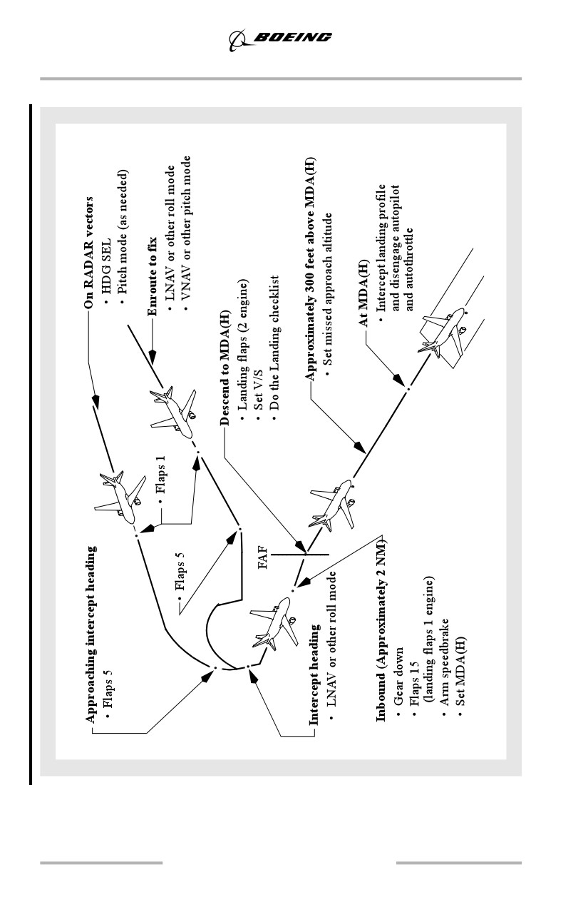
Approaching intercept heading, select flaps 5 and select LNAV or other
appropriate roll mode. Approaching the FAF (approximately 2 NM), select gear
down and flaps 15 and adjust speed. Set the MCP altitude window to the first
intermediate altitude constraint, or MDA(H) if no altitude constraint exists.
Note: If desired altitude is not at an even 100 foot increment, set the MCP altitude
to the nearest 100 ft. increment above the altitude constraint or MDA(H).
Just before FAF, select landing flaps, slow to final approach speed and do the
Landing checklist. If the charted FAF is too close to the runway to permit a
stabilized approach, consider establishing final approach pitch mode and
configuring for approach and landing earlier than specified in the FCOM
procedure.
At or after the FAF, select V/S mode and descend at appropriate vertical speed to
arrive at the MDA(H) at a distance from the runway (VDP) to allow a normal
landing profile. Initial selection of an appropriate V/S should be made considering
the recommended vertical speeds that are published on the approach chart, if
available. These recommended vertical speeds vary with the airplane's ground
speed on final approach. If no recommended vertical speeds are available, set
approximately -700 to -800 fpm.
When stabilized in a descent on final approach, use one of the following
techniques to make small incremental changes to the resulting vertical speed to
achieve a constant angle descent to minimums. There should be no level flight
segment at minimums.
5.51
Approach and Missed Approach
Several techniques may be used to achieve a constant angle path that arrives at
MDA(H) at or near the VDP:
• the most accurate technique is to monitor the VNAV path deviation
indication on the map display and adjust descent rate to maintain the
airplane on the appropriate path. This technique requires the path to be
defined appropriately on the LEGS page and that the header GPx.xx is
displayed for the missed approach point or there is a RWxx, MXxx, or
named waypoint on the legs page with an altitude constraint which
corresponds to approximately 50 ft. threshold crossing height. When this
method is used, crews must ensure compliance with each minimum
altitude constraint on the final approach segment (step down fixes).
• select a descent rate that places the altitude range arc at or near the
stepdown fix or visual descent point (VDP). This technique requires the
stepdown fix or MDA(H) to be set in the MCP and may be difficult to use
in turbulent conditions. See the Visual Descent Point section for more
details on determining the VDP.
• using 300 feet per mile for a 3° path, determine the desired HAA which
corresponds to the distance in NM from the runway end. The PM can then
call out recommended altitudes as the distance to the runway changes
(Example: 900 feet - 3 NM, 600 feet - 2NM, etc.). The descent rate should
be adjusted in small increments for significant deviations from the
nominal path.
Be prepared to land or go-around from the MDA(H) at the VDP. Note that a
normal landing cannot be completed from the published missed approach point on
many instrument approaches.
Approximately 300 feet above the MDA(H), select the missed approach altitude.
Leaving the MDA(H), disengage the autopilot and disconnect the autothrottle.
Turn both F/Ds OFF, then place both F/Ds ON. This eliminates unwanted
commands for both pilots and allows F/D guidance in the event of a go-around.
Complete the landing.
Minimum Descent Altitude/Height (MDA(H))
The pilot monitoring should expand the instrument scan to include outside visual
cues when approaching MDA(H). Do not continue the approach below MDA(H)
unless the airplane is in a position from which a normal approach to the runway
of intended landing can be made and suitable visual reference can be maintained.
Upon arrival at MDA(H) or any time thereafter, if any of the above requirements
are not met, immediately execute the missed approach procedure.
When suitable visual reference is established, maintain the descent path to the
flare. Do not descend below the visual glide path.
5.52
Approach and Missed Approach
Visual Descent Point
For a non-ILS approach, the VDP is defined as the position on final approach from
which a normal descent from the MDA(H) to the runway touchdown point may
be initiated when suitable visual reference is established. If the airplane arrives at
the VDP, a stabilized visual segment is much easier to achieve since little or no
flight path adjustment is required to continue to a normal touchdown.
VDPs are indicated on some non-ILS approach charts by a "V" symbol. The
distance to the runway is shown below the “V” symbol. If no VDP is given, the
crew can determine the point where to begin the visual descent by determining the
height above the airport (HAA) of the MDA(H) and use 300 feet per NM distance
to the runway.
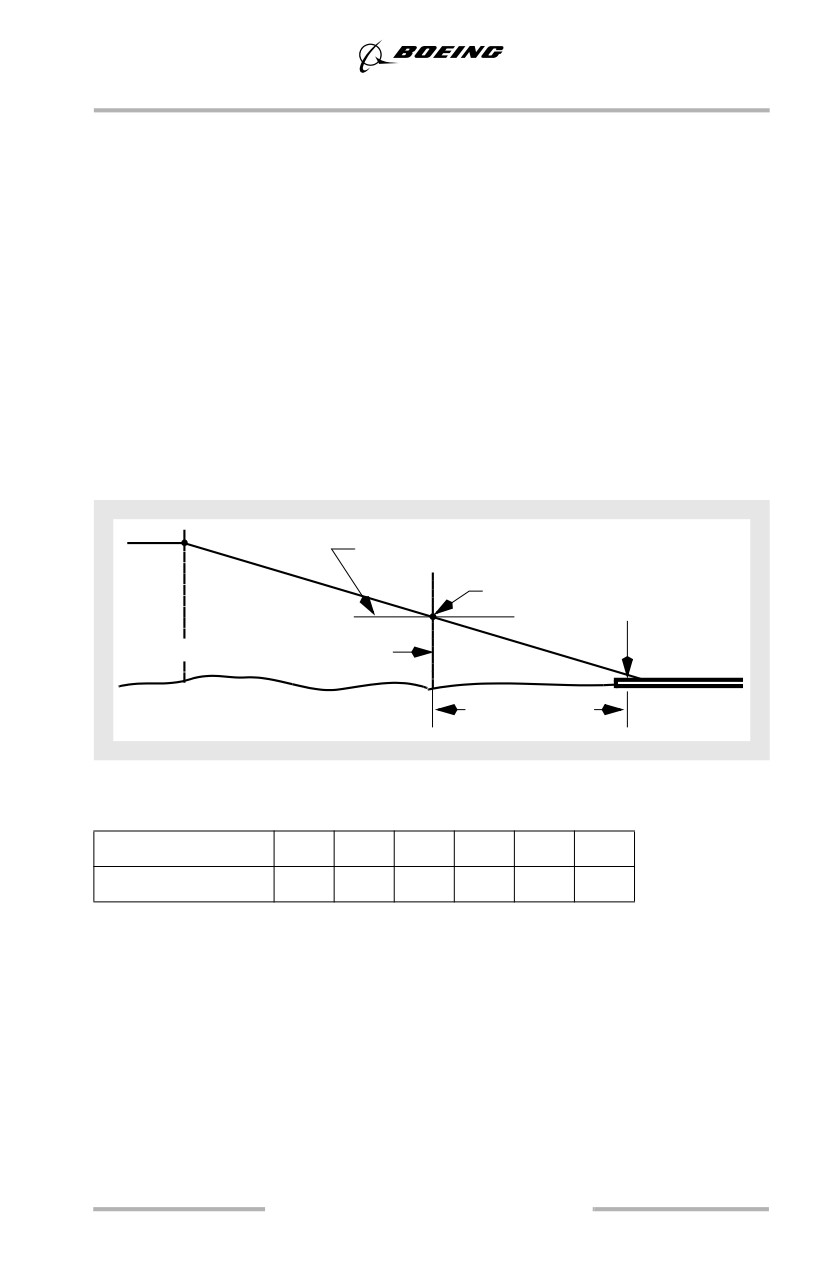
In the following example, an MDA(H) of 550 feet MSL with a 100 feet
touchdown zone elevation results in a HAA of 450 feet. At 300 feet per NM, the
point to begin the visual descent is 1 ½ NM distance from the runway.
MDA(H)
550 ft
VDP
Touchdown zone
elevation (100 ft)
FAF
HAA (450 ft)
VDP (1.5 NM)
Most VDPs are between 1 and 2 NM from the runway. The following table
provides more examples.
HAA (feet)
300
400
450
500
600
700
VDP Distance, NM
1.0
1.3
1.5
1.7
2.0
2.3
Note: If flying a VNAV path approach and the airplane remains on the published
path, then the VDP is automatically complied with when the airplane
arrives at the DA(H) or MDA(H). It is not necessary to determine the point
to begin the visual descent for VNAV path approaches for this reason.
When flying an instrument approach using V/S, if the pilot adjusts the altitude
range arc to approximately the VDP distance in front of the runway by varying the
vertical speed, the airplane will remain close to or on the proper path for typical
non-ILS approaches.
5.53
Approach and Missed Approach
Missed Approach - Non-ILS
Refer to Go-Around and Missed Approach - All Approaches, this chapter.
5.54
Approach and Missed Approach
Circling Approach
5.55
Approach and Missed Approach
Circling Approach - General
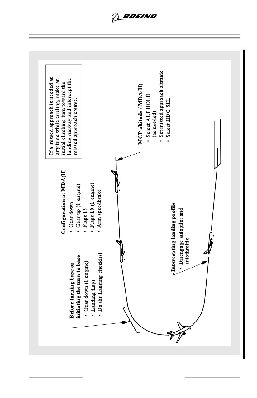
The circling approach should be flown with landing gear down, flaps 15, and at
flaps 15 maneuvering speed. Use the weather minima associated with the
anticipated circling speed. Maintain MCP altitude or MDA(H) using ALT HOLD
mode and use HDG SEL for the maneuvering portion of the circling approach. If
circling from an ILS approach, fly the ILS in VOR/LOC and VNAV or V/S
modes.
Note: If the MDA(H) does not end in “00”, set the MCP altitude to the nearest
100 feet above the MDA(H) and circle at MCP altitude.
Use of the APP mode for descent to a circling approach is not recommended for
several reasons:
• the AFDS does not level off at MCP altitude
• exiting the APP mode requires initiating a go-around or disconnecting the
autopilot and turning off the flight directors.
Note: If VNAV ALT (as installed) is allowed to remain as the pitch mode during
the circling maneuver with a higher altitude, (e.g., missed approach
altitude), set in the MCP, the VNAV ALT pitch mode will revert to CWS P.
When in altitude hold at MCP altitude or MDA(H) and before commencing the
circling maneuver, set the missed approach altitude.
Before turning base or when initiating the turn to base leg, select landing flaps and
begin decelerating to the approach speed plus wind correction. To avoid
overshooting final approach course, adjust the turn to final to initially aim at the
inside edge of the runway threshold. Timely speed reduction also reduces turning
radius to the runway. Do the Landing checklist. Do not descend below MDA(H)
until intercepting the visual profile to the landing runway.
Leaving MDA(H), disengage the autopilot and autothrottle. After intercepting the
visual profile, cycle both F/D to OFF, then to ON. This eliminates unwanted
commands for both pilots and allows F/D guidance in the event of a go-around.
Complete the landing.
Note: If a go-around is selected with either flight director switch in the OFF
position, the flight director pitch or roll command bar on the corresponding
side will disappear when the first pitch or roll mode is selected or engaged.
Obstruction Clearance
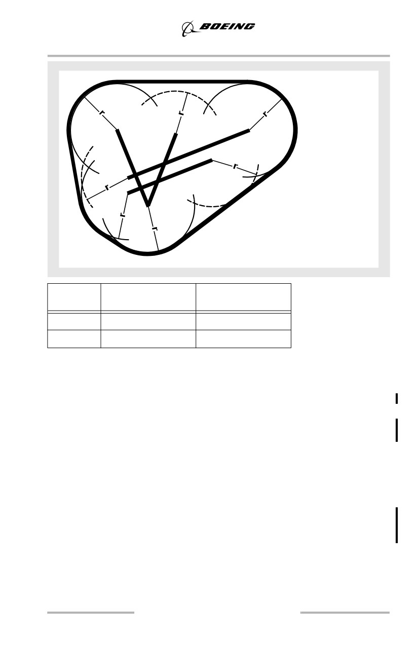
Obstruction clearance areas during the circling approach are depicted in the
following figure. Distances are determined by aircraft approach category. Adjust
airplane heading and timing so that the airplane ground track does not exceed the
obstruction clearance distance from the runway at any time during the circling
approach.
5.56
Approach and Missed Approach
Radius (r), defining size of
areas, varies with airplane
category.
Aircraft
FAA Obstruction
ICAO Obstruction
Category
Clearance Radius (r)
Clearance Radius (r)
C
1.7 NM
4.2 NM
D
2.3 NM
5.28 NM
Circling Approach - One Engine Inoperative
If a circling approach is anticipated, maintain gear up, flaps 10, and flaps 10
maneuvering speed from the final approach fix until just before turning base. As
an option, use flaps 5, and flaps 5 maneuvering speed as the approach flaps setting
for the circling approach. Before turning base or when initiating the turn to base
leg, select gear down and flaps 15 and begin reducing speed to VREF 15 + wind
correction. Do not descend below MDA(H) until intercepting the visual profile.
Missed Approach - Circling
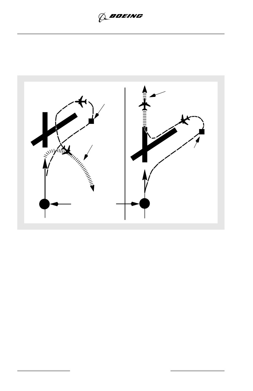
If a missed approach is required at any time while circling, make a climbing turn
in the shortest direction toward the landing runway. This may result in a turn
greater than 180° to intercept the missed approach course. Continue the turn until
established on an intercept heading to the missed approach course corresponding
to the instrument approach procedure just flown. Maintain the missed approach
flap setting until close-in maneuvering is completed.
5.57
Approach and Missed Approach
Different patterns may be required to become established on the prescribed missed
approach course. This depends on airplane position at the time the missed
approach is started. The following figure illustrates the maneuvering that may be
required. This ensures the airplane remains within the circling and missed
approach obstruction clearance areas.
Visual
Published
reference
missed
lost here
approach
Published
missed
Visual
approach
reference
lost here
Approach fix
In the event that a missed approach must be accomplished from below the
MDA(H), consideration should be given to selecting a flight path which assures
safe obstacle clearance until reaching an appropriate altitude on the specified
missed approach path.
Refer to Go-Around and Missed Approach - All Approaches, this chapter.
5.58
Approach and Missed Approach
Visual Traffic Pattern
5.59
Approach and Missed Approach
Visual Approach - General
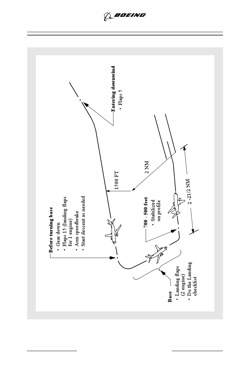
The recommended landing approach path is approximately 2 1/2° to 3°. Once the
final approach is established, the airplane configuration remains fixed and only
small adjustments to the glide path, approach speed, and trim are necessary. This
results in the same approach profile under all conditions.
Thrust
Engine thrust and elevators are the primary means to control attitude and rate of
descent. Adjust thrust slowly using small increments. Sudden large thrust changes
make airplane control more difficult and are indicative of an unstable approach.
No large changes should be necessary except when performing a go-around. Large
thrust changes are not required when extending landing gear or flaps on downwind
and base leg. A thrust increase may be required when stabilizing on speed on final
approach.
Downwind and Base Leg
Fly at an altitude of 1500 feet above the runway elevation and enter downwind
with flaps 5 at flaps 5 maneuvering speed. Maintain a track parallel to the landing
runway approximately 2 NM abeam.
Before turning base leg, extend the landing gear, select flaps 15, arm the
speedbrake, and slow to flaps 15 maneuvering speed or approach speed plus wind
correction if landing at flaps 15. If the approach pattern must be extended, delay
lowering gear and selecting flaps 15 until approaching the normal visual approach
profile. Turning base leg, adjust thrust as required while descending at
approximately 600-700 fpm.
Extend landing flaps before turning final. Allow the speed to decrease to the
proper final approach speed and trim the airplane. Do the Landing checklist. When
established in the landing configuration, maneuvering to final approach may be
accomplished at final approach speed (VREF + wind correction).
5.60
Approach and Missed Approach
Final Approach
Roll out of the turn to final on the extended runway centerline and maintain the
appropriate approach speed. An altitude of approximately 300 feet above airport
elevation for each mile from the runway provides a normal approach profile.
Attempt to keep thrust changes small to avoid large trim changes. With the
airplane in trim and at target airspeed, pitch attitude should be approximately the
normal approach body attitude. At speeds above approach speed, pitch attitude is
less. At speeds below approach speed, pitch attitude is higher. Slower speed
reduces aft body clearance at touchdown. Stabilize the airplane on the selected
approach airspeed with an approximate rate of descent between 700 and 900 feet
per minute on the desired glide path, in trim. Stabilize on the profile by 500 feet
above touchdown.
Note: Descent rates greater than 1,000 fpm should be avoided.
With one engine inoperative, the rudder trim may be centered before landing. This
allows most of the rudder pedal pressure to be removed when the thrust of the
operating engine is retarded to idle at touchdown.
Full rudder authority and rudder pedal steering capability are not affected by
rudder trim. If touchdown occurs with the rudder still trimmed for the approach,
be prepared for the higher rudder pedal forces required to track the centerline on
rollout.
Engine Failure On Final Approach
In case of engine failure on visual final approach, use the procedure described in
the ILS approach section, this chapter.
5.61
Approach and Missed Approach
Touch and Go Landings
5.62
Approach and Missed Approach
Touch and Go Landing - General
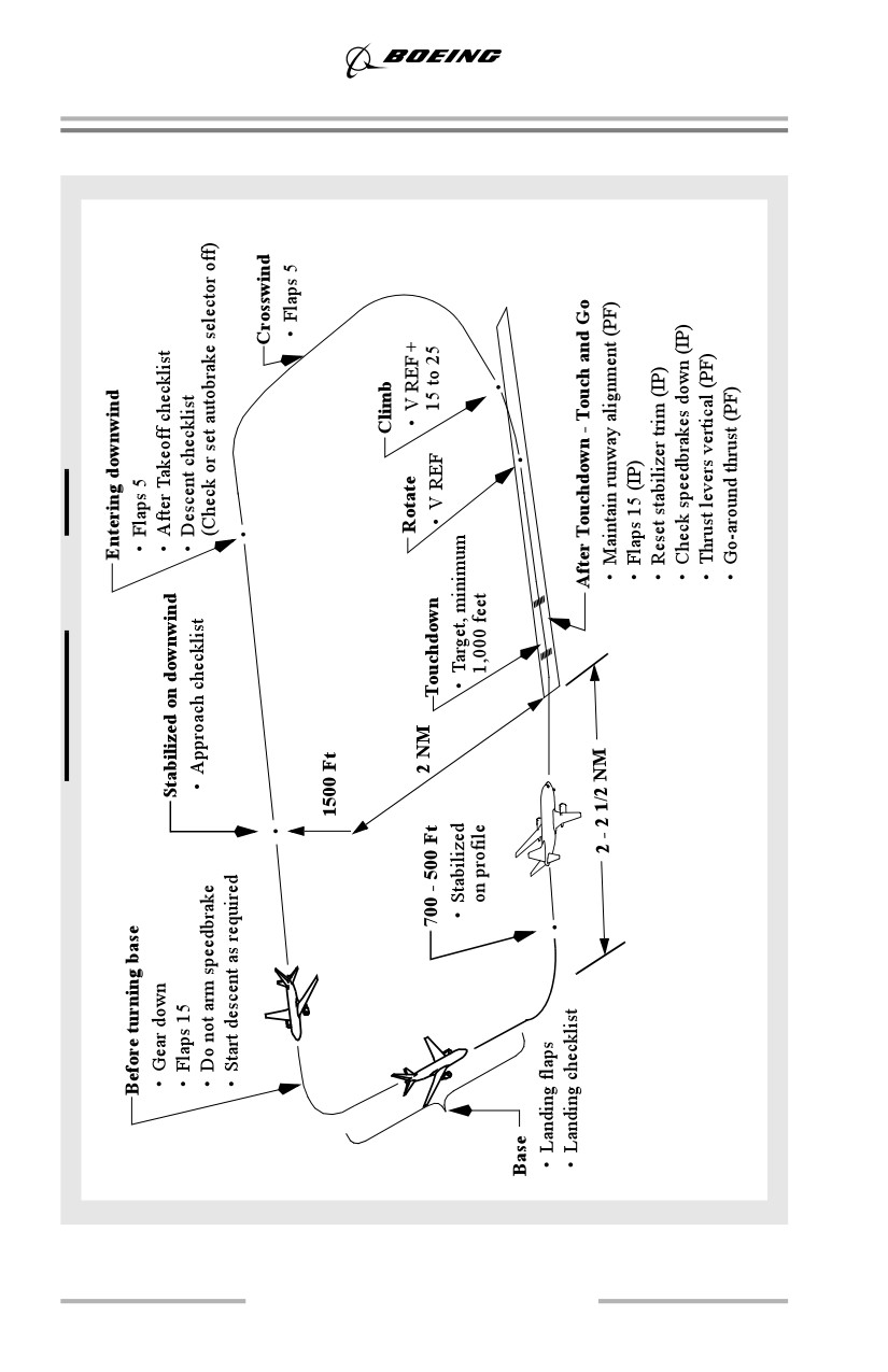
The primary objective of touch and go landings is approach and landing practice.
It is not intended for landing roll and takeoff procedure training.
Approach
Accomplish the pattern and approach procedures as illustrated.The landing gear
may remain extended throughout the maneuver for brake cooling, but be prepared
to retract the landing gear if an actual engine failure occurs during go-around. Do
not arm the speedbrakes. Select the autobrakes OFF.
Landing
The trainee should accomplish a normal final approach and landing. After
touchdown, the instructor selects flaps 15, sets stabilizer trim, ensures
speedbrakes are down, and at the appropriate time instructs the trainee to move the
thrust levers to approximately the vertical position (so engines stabilize before
applying go-around thrust). When the engines are stabilized, the instructor
instructs the trainee to set thrust.
Note: Flaps 15 is recommended after touchdown to minimize the possibility of a
tailstrike during the takeoff.
WARNING: After reverse thrust is initiated, a full stop landing must be
made.
At VREF, the instructor calls “ROTATE” and the trainee rotates smoothly to
approximately 15 ° pitch and climb at VREF + 15 to 25 knots. The takeoff warning
horn may sound momentarily if the flaps have not retracted to flaps 15 and the
thrust levers are advanced to approximately the vertical position.
Stop and Go Landings
The objective of stop and go landings is to include landing roll, braking, and
takeoff procedure practice in the training profile.
Note: At high altitude airports, or on extremely hot days, stop and go landings are
not recommended.
After performing a normal full-stop landing, a straight ahead takeoff may be
performed if adequate runway is available (FAR field length must be available).
After stopping, and before initiating the takeoff, accomplish the following:
• set takeoff flaps
• trim the stabilizer for takeoff
• place speedbrake lever in the down detent
• place autobrake to RTO
5.63
Approach and Missed Approach
• check the rudder trim
• set airspeed bugs for the flap setting to be used.
Perform a normal takeoff.
Do not make repeated full stop landings without allowing time for brake cooling.
Brake heating is cumulative and brake energy limits may be exceeded. Flat tires
may result.
Note: Flying the pattern with the gear extended assists in brake cooling.
5.64
Approach and Missed Approach
Go-Around and Missed Approach - All Approaches
5.65
Approach and Missed Approach
Go-Around and Missed Approach - All Engines Operating
The go-around and missed approach is generally performed in the same manner
whether an instrument or visual approach was flown. The go-around and missed
approach is flown using the Go-Around and Missed Approach procedure
described in the FCOM. The discussion in this section supplements those
procedures.
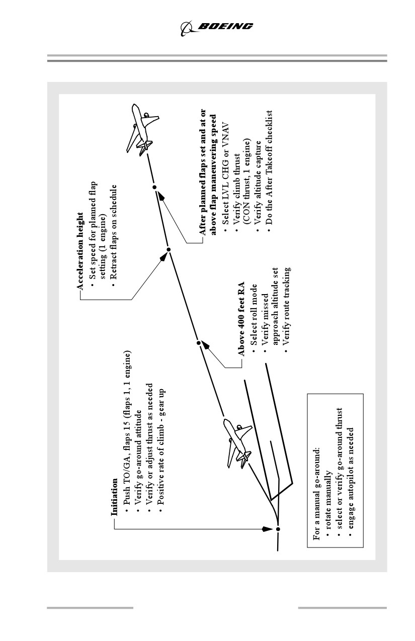
If a missed approach is required following a dual autopilot approach with FLARE
arm annunciated, leave the autopilots engaged. Push either TO/GA switch, call for
flaps 15, ensure go-around thrust for the nominal climb rate is set and monitor
autopilot performance. Retract the landing gear after a positive rate of climb is
indicated on the altimeter.
At typical landing weights, actual thrust required for a normal go-around is
usually considerably less than maximum go-around thrust. This provides a thrust
margin for windshear or other situations requiring maximum thrust. If full thrust
is desired after thrust for the nominal climb rate has been established, press
TO/GA a second time.
If a missed approach is required following a single autopilot or manual instrument
approach, or a visual approach, push either TO/GA switch, call for flaps 15,
ensure/set go-around thrust, and rotate smoothly toward 15° pitch attitude. Then
follow flight director commands and retract the landing gear after a positive rate
of climb is indicated on the altimeter.
Note: Use flaps 1 if a go-around is required from a flaps 15 all engine approach.
Bank angles must be limited to 15° until VREF 15 + 15 knots is attained.
During an automatic go-around initiated at 50 feet, approximately 30 feet of
altitude is lost. If touchdown occurs after a go-around is initiated, the go-around
continues. Observe that the autothrottles apply go-around thrust or manually apply
go-around thrust as the airplane rotates to the go-around attitude.
Note: An automatic go-around cannot be initiated after touchdown.
The TO/GA pitch mode initially commands a go-around attitude and then
transitions to speed as the rate of climb increases. Command speed automatically
moves to a target airspeed for the existing flap position. The TO/GA roll mode
maintains existing ground track. Above 400 feet AGL, select a roll mode as
appropriate.
5.66
Approach and Missed Approach
The minimum altitude for flap retraction during a normal takeoff is not normally
applicable to a missed approach procedure. However, obstacles in the missed
approach flight path must be taken into consideration. During training, use 1,000
feet AGL to initiate acceleration for flap retraction, as during the takeoff
procedure.
Note: Selection of pitch and roll modes below 400 feet AGL does not change the
autopilot and flight director modes.
Note: When accomplishing a missed approach from a dual-autopilot approach,
initial selection of a pitch mode, or when altitude capture occurs above 400
feet AGL the autopilot reverts to single autopilot operation.
If initial maneuvering is required during the missed approach, accomplish the
missed approach procedure through gear up before initiating the turn. Delay
further flap retraction until initial maneuvering is complete and a safe altitude and
appropriate speed are attained.
Command speed automatically increases to maneuvering speed for the existing
flap position. Retract flaps on the normal flap/speed schedule. When the flaps are
retracted to the desired position and the airspeed approaches maneuvering speed,
select LVL CHG and ensure climb thrust is set. VNAV may be selected if the flaps
are up. Verify the airplane levels off at selected altitude and proper speed is
maintained.
If VNAV is used during go-around, the FMC missed approach profile should
contain the appropriate holding speeds and altitudes. Before selecting VNAV,
flaps should be retracted because VNAV does not provide overspeed protection
for the leading edge devices. Speed intervention (as installed) may be used to
further modify airspeed as needed. If VNAV ALT (as installed) is displayed, a
premature level off may occur and selection of LVL CHG may be required to
complete the climb to the missed approach altitude.
If a diversion to an alternate airport is required, delay use of VNAV until
appropriate FMC entries are completed.
Note: FMC speeds may not comply with speed/altitude restrictions when using
VNAV at low altitudes.
Go-Around after Touchdown
If a go-around is initiated before touchdown and touchdown occurs, continue with
normal go-around procedures. The F/D go-around mode will continue to provide
go-around guidance commands throughout the maneuver.
If a go-around is initiated after touchdown but before thrust reverser selection,
auto speedbrakes retract and autobrakes disarm as thrust levers are advanced. The
F/D go-around mode will not be available until go-around is selected after
becoming airborne.
5.67
Approach and Missed Approach
Once reverse thrust is initiated following touchdown, a full stop landing must be
made. Factors dictating this are:
• five seconds are required for a reverser to transition to the forward thrust
position
• a possibility exists that a reverser may not stow in the forward thrust
position.
Go-Around and Missed Approach - One Engine Inoperative
If a missed approach is accomplished from a flaps 15 approach, use flaps 1 for the
go-around flap setting. After TO/GA is engaged, the AFDS initially commands a
go-around attitude, then transitions to maintain command speed as the rate of
climb increases. The pilot must control yaw with rudder and trim. Some rudder
pedal pressure may be required even with full rudder trim. Select maximum
continuous thrust when flaps are retracted to the desired flap setting.
For fail operational airplanes, if a missed approach is accomplished from a flaps
30 approach, perform a flaps 15 go-around. Follow Go-Around and Missed
Approach procedures. After TO/GA is engaged, the AFDS initially commands a
go-around attitude, then transitions to maintain command speed as the rate of
climb increases. If the missed approach is initiated after LAND 2 or LAND 3 is
annunciated, yaw is initially controlled by the autopilots. Be prepared to
immediately apply rudder input when selecting another roll mode, pitch mode, or
when altitude capture occurs above 400 feet AGL because the autopilot reverts to
single autopilot operation. The system reverts to normal autopilot operation and
automatic control of rudder is discontinued.
Engine Failure During Go-Around and Missed Approach
If an engine fails during go-around, perform normal Go-Around and Missed
Approach procedures. Verify maximum go-around thrust is set. Maintain flaps 15,
VREF 30 or 40 + wind correction (5 knots minimum) speed and limit bank angle
to 15° until initial maneuvering is complete and a safe altitude is reached.
Accelerate to flap retraction speed by repositioning the command speed to the
maneuvering speed for the desired flap setting and adjusting pitch. Retract flaps
on the normal flap/speed schedule.
5.68
Landing
Chapter 6
Table of Contents
Section TOC
6.TOC Landing-Table of Contents
Preface
6.1
Landing Configurations and Speeds
6.1
Maneuver Margin
6.1
Non-Normal Landing Configurations and Speeds
6.1
Non-Normal Landing Distance
6.2
Visual Approach Slope Indicator (VASI/T - VASI)
6.3
Three Bar VASI/T - VASI
6.4
VASI Landing Geometry
6.5
Precision Approach Path Indicator (PAPI)
6.7
PAPI Landing Geometry
6.7
Landing Geometry
6.7
Visual Aim Point
6.7
Runway Markings (Typical)
6.8
Threshold Height
6.9
Flare and Touchdown
6.9
Landing Flare Profile
6.9
Bounced Landing Recovery
6.10
Rejected Landing
6.11
Normal Touchdown Attitude
6.11
Body Clearance at Touchdown
6.16
Pitch and Roll Limit Conditions
6.20
Landing Roll
6.22
Speedbrakes
6.22
Directional Control and Braking during Landing Roll
6.23
6.TOC.1
Landing -
Table of Contents
Factors Affecting Landing Distance
6.23
Wheel Brakes
6.27
Reverse Thrust Operation
6.30
Crosswind Landings
6.34
Landing Crosswind Guidelines
6.34
Crosswind Landing Techniques
6.35
Overweight Landing
6.36
Overweight Autolands Policy
6.37
6.TOC.2
Landing
Chapter 6
Preface
This chapter outlines recommended operating practices and techniques for
landing, rejected landings and landing roll. Techniques are provided to help the
pilot effectively utilize approach lighting, control the airplane during crosswind
landings and maintain directional control after landing. Additionally, information
on factors affecting landing distance and landing geometry is provided.
Landing Configurations and Speeds
Flaps 15 (except JAA), 30 (for noise abatement) and 40 are normal landing flap
positions. Flaps 15 is normally limited to airports where approach climb
performance is a factor. Runway length and condition must be taken into account
when selecting a landing flap position.
Maneuver Margin
Flight profiles should be flown at, or slightly above, the recommended
maneuvering speed for the existing flap configuration. These speeds approximate
maximum fuel economy and allow full maneuvering capability (25° bank with a
15° overshoot).
Full maneuver margin exists for all normal and non-normal landing procedures
whenever speed is at or above the maneuver speed for the current flap setting. Full
maneuver margin exists with flaps 15 at VREF 30 + 5 or VREF 40 + 5 during a
go-around at go-around thrust.
Airspeeds recommended for non-normal flight profiles are intended to restore
near normal maneuvering margins and/or aerodynamic control response.
The configuration changes are based on maintaining full maneuvering and/or
maximum performance unless specified differently in individual procedures. It is
necessary to apply wind correction to the VREF speeds. See the Command Speed
section in chapter 1 for an explanation of wind corrections.
Non-Normal Landing Configurations and Speeds
The Non-Normal Configuration Landing Distance table in the PI chapter of the
QRH shows speeds and landing distances for various non-normal landing
configurations and runway conditions. The target speed for the approach is the
appropriate approach VREF plus the wind and gust additives.
6.1
Landing
Non-Normal Landing Distance
Because of higher approach speeds associated with the non-normal landing
condition the actual landing distance is increased. The flight crew should review
the Non-Normal Configuration Landing Distance information in the PI chapter of
the QRH.
6.2
Landing
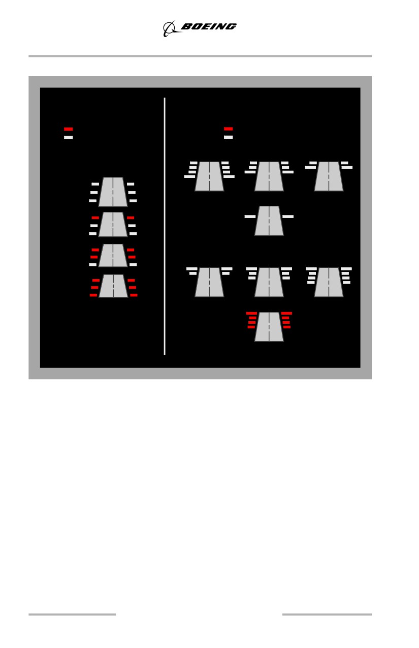
Visual Approach Slope Indicator (VASI/T - VASI)
The VASI is a system of lights arranged to provide visual descent guidance
information during the approach. All VASI systems are visual projections of the
approach path normally aligned to intersect the runway at a point 1,000 or 1,800
feet beyond the threshold. Flying the VASI glide slope to touchdown is the same
as selecting a visual aim point on the runway adjacent to the VASI installation.
When using a two-bar VASI, the difference between the eye reference path and the
gear path results in a normal approach and threshold height. It provides useful
information in alerting the crew to low profile situations.
Some airports have three-bar VASI which provides two visual glide paths. The
additional light bar is located upwind from a standard two-bar installation. When
the airplane is on the glide path, the pilot sees the one white bar and two red bars.
Three-bar VASI may be safely used with respect to threshold height, but may
result in landing further down the runway.
For a T-VASI, flying the approach with one additional white fly down light visible
provides additional wheel clearance.
6.3
Landing
Three Bar VASI/T - VASI
Visual Approach Slope
Visual Approach Slope
Indicator (VASI)
Indicator (T-VASI)
Red VASI Lights
Red T-VASI Lights
White VASI Lights
White T-VASI Lights
Fly Down Lights
Standard (3-bar)
High
Very High
High
Slightly High
Above
Glide
Path
On Glide Path
On
Fly Up Lights
Glide Path
Below
Glide Path
Slightly Low
Low
Very Low
Well Below
Glide Path
6.4
Landing
VASI Landing Geometry
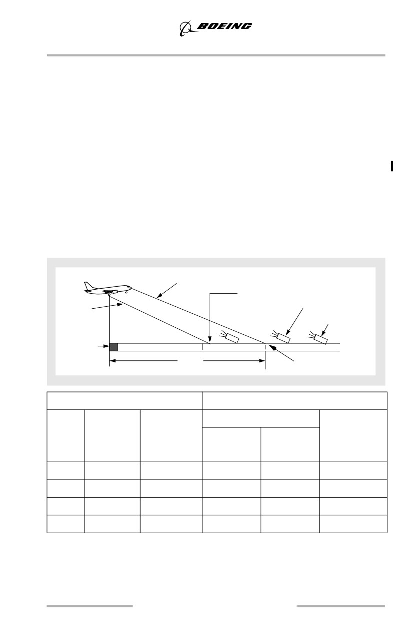
Two-bar VASI installations provide one visual glide path which is normally set at
3°. Three-bar VASI installations provide two visual glide paths. The lower glide
path is provided by the near and middle bars and is normally set at 3° while the
upper glide path, provided by the middle and far bars, is normally 1/4° higher
(3.25°). This higher glide path is intended for use only by high cockpit (long
wheelbase) airplanes to provide a sufficient threshold crossing height.
Two Bar VASI Landing Geometry
The following diagrams use these conditions:
• data is based upon typical landing weight
• airplane body attitudes are based on Flaps 30 and Flaps 40, VREF (for the
flap setting used) + 5 and should be reduced by 1° for each 5 knots above
this speed.
• eye height is calculated at the moment the main gear is over the threshold.
VASI Glide Path
Main Gear
Touchdown Point
Main
VASI Lights
(No Flare)
Gear Path
3 Bar VASI
(only)
Threshold
1000’
Aim point
Flaps 30
AIM Point at 1,000 Feet
737
Visual Glide
Airplane
Threshold Height
Main Gear
Model
Path
Body Attitude
Touchdown
Pilot Eye
Main Gear
(degrees)
(degrees)
Point - no flare
Height (feet)
Height (feet)
(feet)
-600
3.0
3.7
50
36
657
-700
3.0
3.7
50
34
647
-800
3.0
2.4
49
34
651
-900
3.0
1.6
49
35
659
6.5

Landing
Flaps 40
AIM Point at 1,000 Feet
737
Visual Glide
Airplane
Threshold Height
Main Gear
Model
Path in
Body Attitude
Touchdown
Pilot Eye
Main Gear
(degrees)
(degrees)
Point - no flare
Height (feet)
Height (feet)
(feet)
-600
3.0
2.0
50
36
683
-700
3.0
2.0
50
35
675
-800
3.0
1.4
49
35
671
-900
3.0
0.9
49
34
644
6.6
Landing
Precision Approach Path Indicator (PAPI)
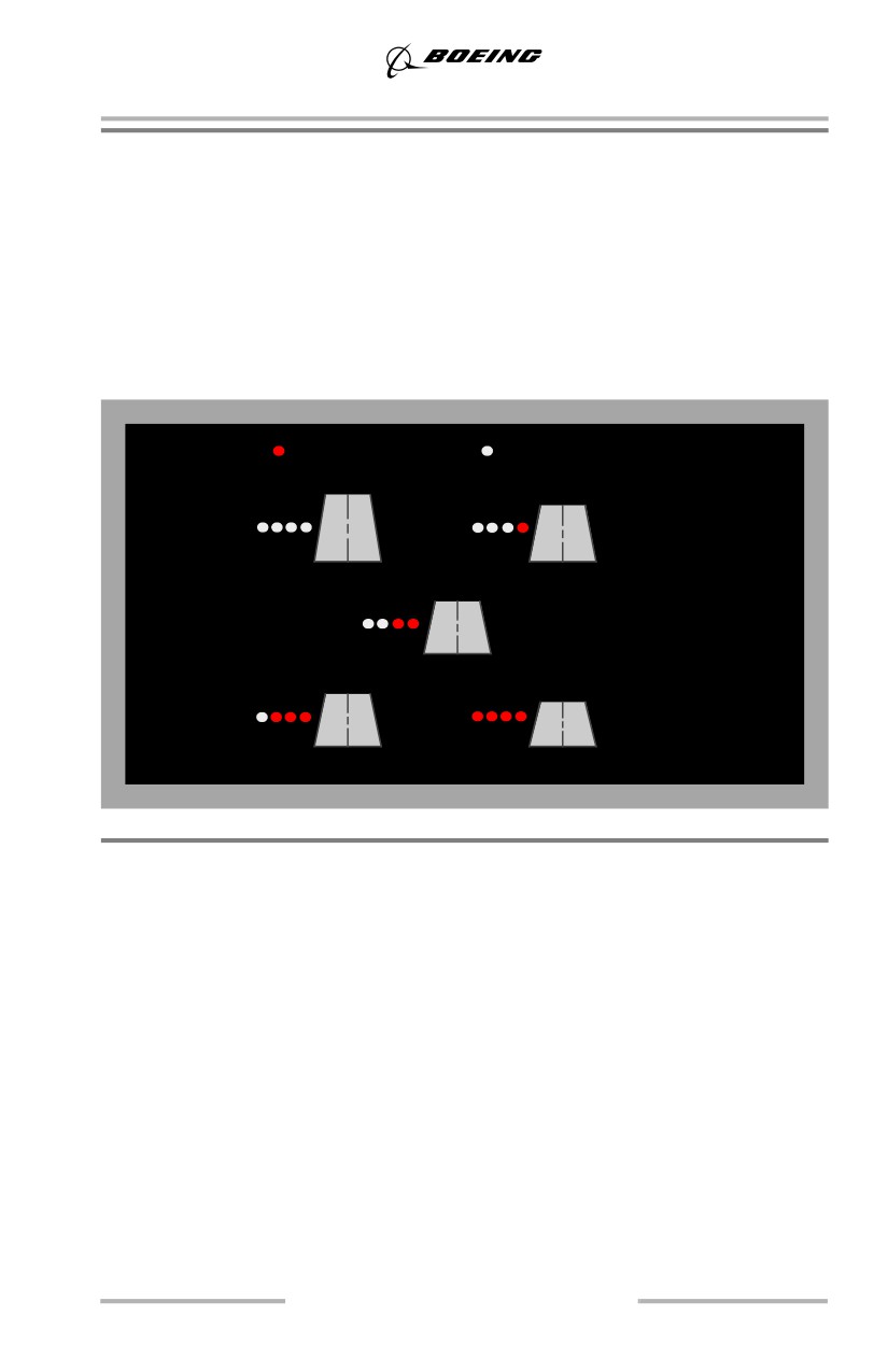
The PAPI uses lights which are normally on the left side of the runway. They are
similar to the VASI, but are installed in a single row of light units.
When the airplane is on a normal 3° glide path, the pilot sees two white lights on
the left and two red lights on the right. The PAPI may be safely used with respect
to threshold height, but may result in landing further down the runway. The PAPI
is normally aligned to intersect the runway 1,000 to 1,500 feet down the runway.
PAPI Landing Geometry
Red PAPI Lights
White PAPI Lights
High
Slightly High
On Glide Path
Slightly Low
Low
Landing Geometry
Visual Aim Point
During visual approaches many techniques and methods are used to ensure main
landing gear touchdown at the desired point on the runway. One of the most
common methods used is to aim at the desired gear touchdown point on the
runway, then adjust the final approach glide path until the selected point appears
stationary in relation to the airplane (the point does not move up or down in the
pilot’s field of view during the approach).
Visual aim points versus gear touchdown point differences increase as glide path
angle decreases as in a flat approach. For a particular visual approach, the
difference between gear path and eye level path must be accounted for by the pilot.
6.7
Landing
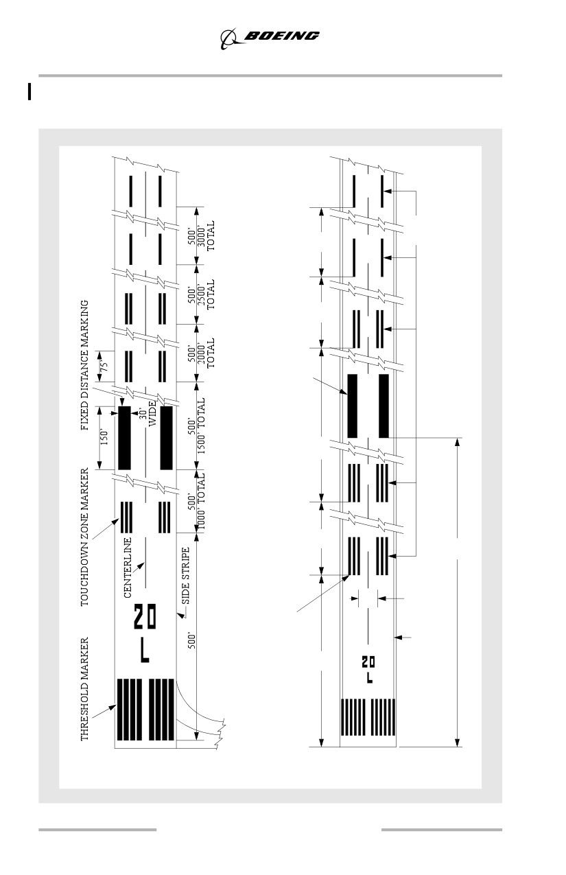
Runway Markings (Typical)
The following runway markings are for runways served by a precision approach.
TOUCHDOWN
ZONE
150m
MARKINGS
(492’)
150m
(492’)
AIMING POINT
MARKINGS
30m (98’) to
60m (197’)
by
4m (13’) to
10m (33’)
300m
(984’)
150m
(492’)
400m
(1312’)
18m (59’) to
22.5m (74’)
STRIPES
1.8m (6’) WIDTH
1.5m (5’) SPACING
RUNWAY
22.5m (74’) MIM
SIDE
STRIPE
LENGTH
150m
MARKINGS
(492’)
United States
ICAO
6.8
Landing
Threshold Height
Threshold height is a function of glide path angle and landing gear touchdown
target. Threshold height for main gear and pilot eye level is shown in the Two
Bar/Three Bar VASI Landing Geometry tables on a previous page. Special
attention must be given to establishing a final approach that assures safe threshold
clearance and gear touchdown at least 1,000 feet down the runway. If automatic
callouts are not available, the radio altimeter should be used to assist the pilot in
judging terrain clearance, threshold height and flare initiation height.
Flare and Touchdown
The techniques discussed here are applicable to all landings including one engine
inoperative landings, crosswind landings and landings on slippery runways.
Unless an unexpected or sudden event occurs, such as windshear or collision
avoidance situation, it is not appropriate to use sudden, violent or abrupt control
inputs during landing. Begin with a stabilized approach on speed, in trim and on
glide path.
When the threshold passes under the airplane nose and out of sight, shift the visual
sighting point to approximately 3/4 the runway length. Shifting the visual sighting
point assists in controlling the pitch attitude during the flare. Maintaining a
constant airspeed and descent rate assists in determining the flare point. Initiate
the flare when the main gear is approximately 15 feet above the runway by
increasing pitch attitude approximately 2° - 3°. This slows the rate of descent.
After the flare is initiated, smoothly retard the thrust levers to idle, and make small
pitch attitude adjustments to maintain the desired descent rate to the runway.
Ideally, main gear touchdown should occur simultaneously with thrust levers
reaching idle. A smooth power reduction to idle also assists in controlling the
natural nose-down pitch change associated with thrust reduction. Hold sufficient
back pressure on the control column to keep the pitch attitude constant. A
touchdown attitude as depicted in the figure below is normal with an airspeed of
approximately VREF plus any gust correction.
Note: Do not trim during the flare or after touchdown. Trimming in the flare
increases the possibility of a tailstrike.
Landing Flare Profile
The following diagrams use these conditions:
•
3° approach glide path
• flare distance is approximately 1,000 to 2,000 feet beyond the threshold
6.9
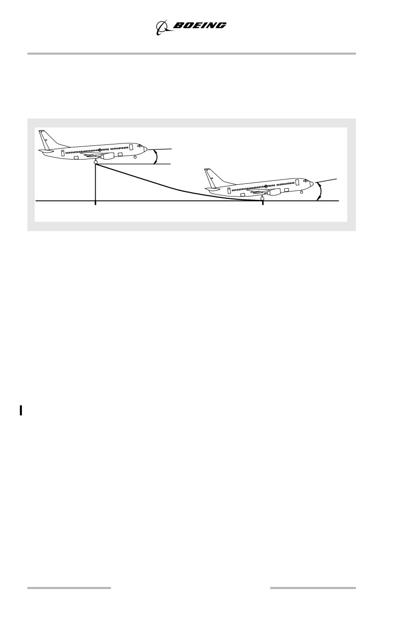
Landing
• typical landing flare times range from 4 to 8 seconds and are a function of
approach speed
• airplane body attitudes are based upon typical landing weights, flaps 30,
VREF 30 + 5 (approach) and VREF 30 + 0 (landing), and should be
reduced by 1° for each 5 knots above this speed.
2° - 4°
h=50’
4°- 7°
Threshold
Touchdown
Typically, the pitch attitude increases slightly during the actual landing, but avoid
over-rotating. Do not increase the pitch attitude after touchdown; this could lead
to a tail strike.
Shifting the visual sighting point down the runway assists in controlling the pitch
attitude during the flare. A smooth power reduction to idle also assists in
controlling the natural nose down pitch change associated with thrust reduction.
Hold sufficient back pressure on the control column to keep the pitch attitude
constant.
Avoid rapid control column movements during the flare. Do not use pitch trim
during flare or after touchdown. Such actions are likely to cause the pitch attitude
to increase at touchdown and increase the potential for a tailstrike. Do not allow
the airplane to float; fly the airplane onto the runway. Do not extend the flare by
increasing pitch attitude in an attempt to achieve a perfectly smooth touchdown.
Do not attempt to hold the nose wheels off the runway.
Bounced Landing Recovery
If the airplane should bounce, hold or re-establish a normal landing attitude and
add thrust as necessary to control the rate of descent. Thrust need not be added for
a shallow bounce or skip. When a high, hard bounce occurs, initiate a go-around.
Apply go-around thrust and use normal go-around procedures. Do not retract the
landing gear until a positive rate of climb is established because a second
touchdown may occur during the go-around.
6.10
Landing
Bounced landings can occur because higher than idle power is maintained through
initial touchdown, disabling the automatic speedbrake deployment even when the
speedbrakes are armed. During the resultant bounce, if the thrust levers are then
retarded to idle, automatic speedbrake deployment can occur resulting in a loss of
lift and nose up pitching moment which can result in a tail strike or hard landing
on a subsequent touchdown.
Rejected Landing
A rejected landing maneuver is trained and evaluated by some operators and
regulatory agencies. Although the FCOM/QRH does not contain a procedure or
maneuver titled Rejected Landing, the requirements of this maneuver can be
accomplished by doing the Go-Around Procedure if it is initiated prior to
touchdown. Refer to Chapter 5, Go-Around after Touchdown, for more
information on this subject.
Normal Touchdown Attitude
The following figures illustrate the effect of airspeed on body attitude on
touchdown. It shows normal touchdown attitude for flaps 30. If flare control and
thrust are excessive near touchdown, the airplane tends to float in ground effect.
With proper airspeed control and thrust management, touchdown occurs at no less
than VREF - 5. The illustration shows that touchdown at a speed significantly
below VREF seriously reduces aft fuselage-runway clearance.
6.11
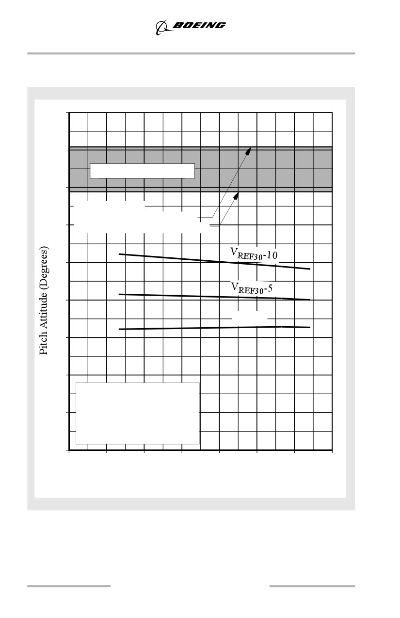
Landing
Touchdown Body Attitudes
737-600
18
16
Body Contact Possible
14
Attitude Limit:
Main Gear Struts Extended
12
Main Gear Struts Compressed
10
8
VREF30
6
4
Flaps 30
Forward CG Limit
2
VTD=VAPP
2.5 fps R/S at Touchdown
Sea Level Standard Day
080
90
100
110
120
130
140
150
(36.4)
(40.1)
(45.5)
(50)
(54.5)
(59.1)
(63.6)
(68.2)
Gross Weight - 1000 lbs (kgs)
6.12
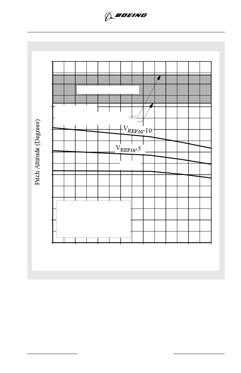
Landing
737-700
16
14
Body Contact Possible
12
Attitude Limit:
Main Gear Struts Extended
Main Gear Struts Compressed
10
8
VREF30
6
4
Flaps 30
Forward CG Limit
2
VTD=VAPP
2.5 fps R/S at Touchdown
Sea Level Standard Day
0
100
110
120
130
140
150
160
170
(45.5)
(50)
(54.5)
(59.1)
(63.6)
(68.2)
(72.6)
(77.1)
Gross Weight - 1000 lbs (kgs)
6.13
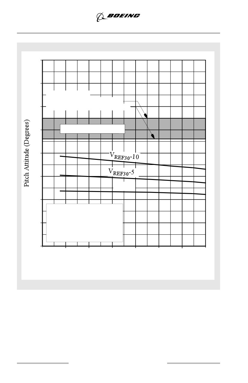
Landing
737-800
16
14
Attitude Limit:
Main Gear Struts Extended
12
Main Gear Struts Compressed
10
Body Contact Possible
8
6
VREF30
4
Flaps 30
Forward CG Limit
2
VTD=VAPP
2.5 fps R/S at Touchdown
Sea Level Standard Day
0
100
110
120
130
140
150
160
170
(45.5)
(50)
(54.5)
(59.1)
(63.6)
(68.2)
(72.6)
(77.1)
Gross Weight - 1000 lbs (kgs)
6.14
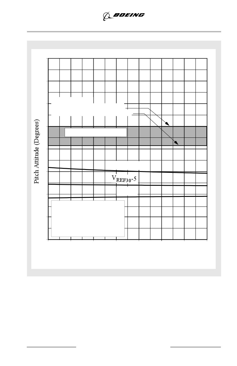
Landing
737-900
16
14
Attitude Limit:
12
Main Gear Struts Extended
Main Gear Struts Compressed
10
Body Contact Possible
8
VREF30-10
6
VREF30
4
Flaps 30
Forward CG Limit
2
VTD=VAPP
2.5 fps R/S at Touchdown
Sea Level Standard Day
0
100
110
120
130
140
150
160
170
(45.5)
(50)
(54.5)
(59.1)
(63.6)
(68.2)
(72.6)
(77.1)
Gross Weight - 1000 lbs (kgs)
6.15
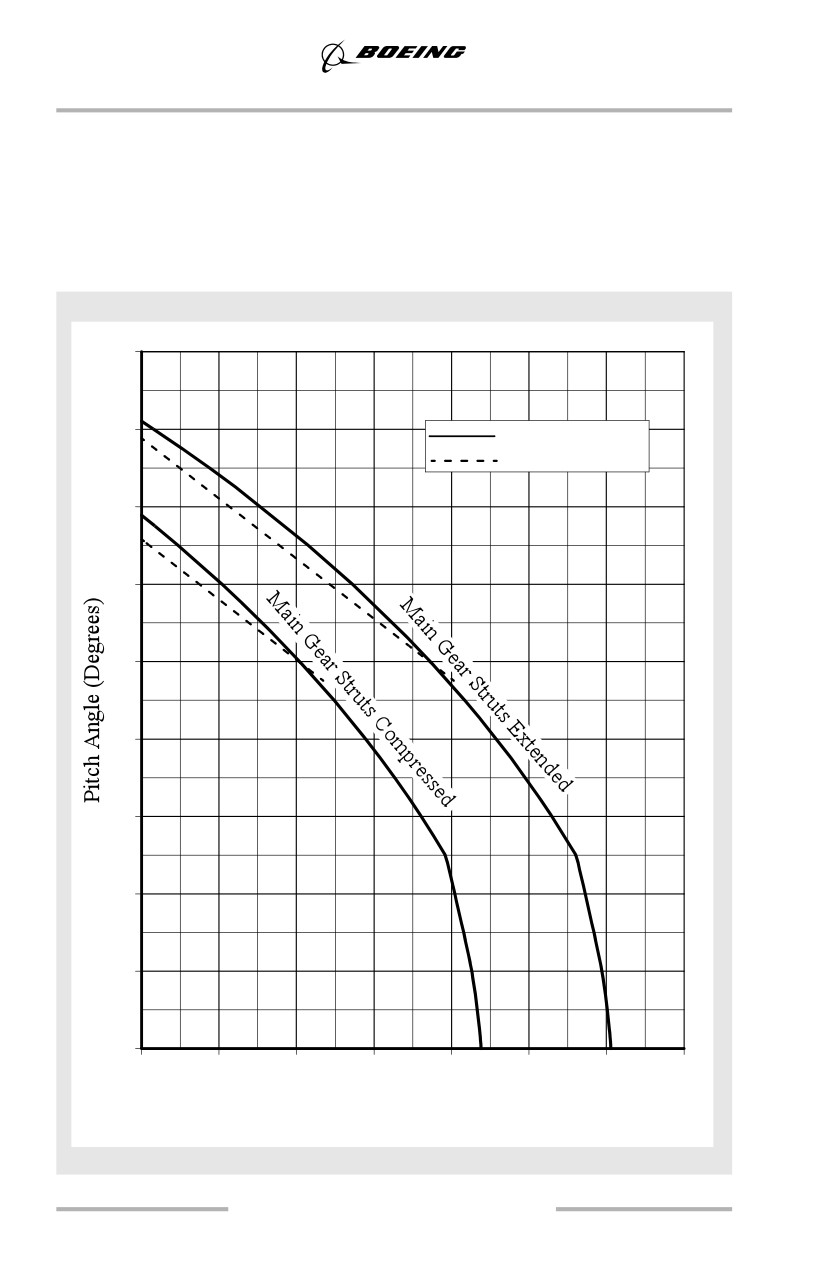
Landing
Body Clearance at Touchdown
The following figures show aft fuselage-runway clearance in relation to pitch
angle with all main gear tires on the runway.
Body Clearance above Ground
737-600
18
16
Aft Body
Aft Drain Mast
14
12
10
8
6
4
2
0
0
10
20
30
40
50
60
70
(0)
(25)
(51)
(76)
(102)
(127)
(152)
(178)
Clearance - inches (cm)
6.16
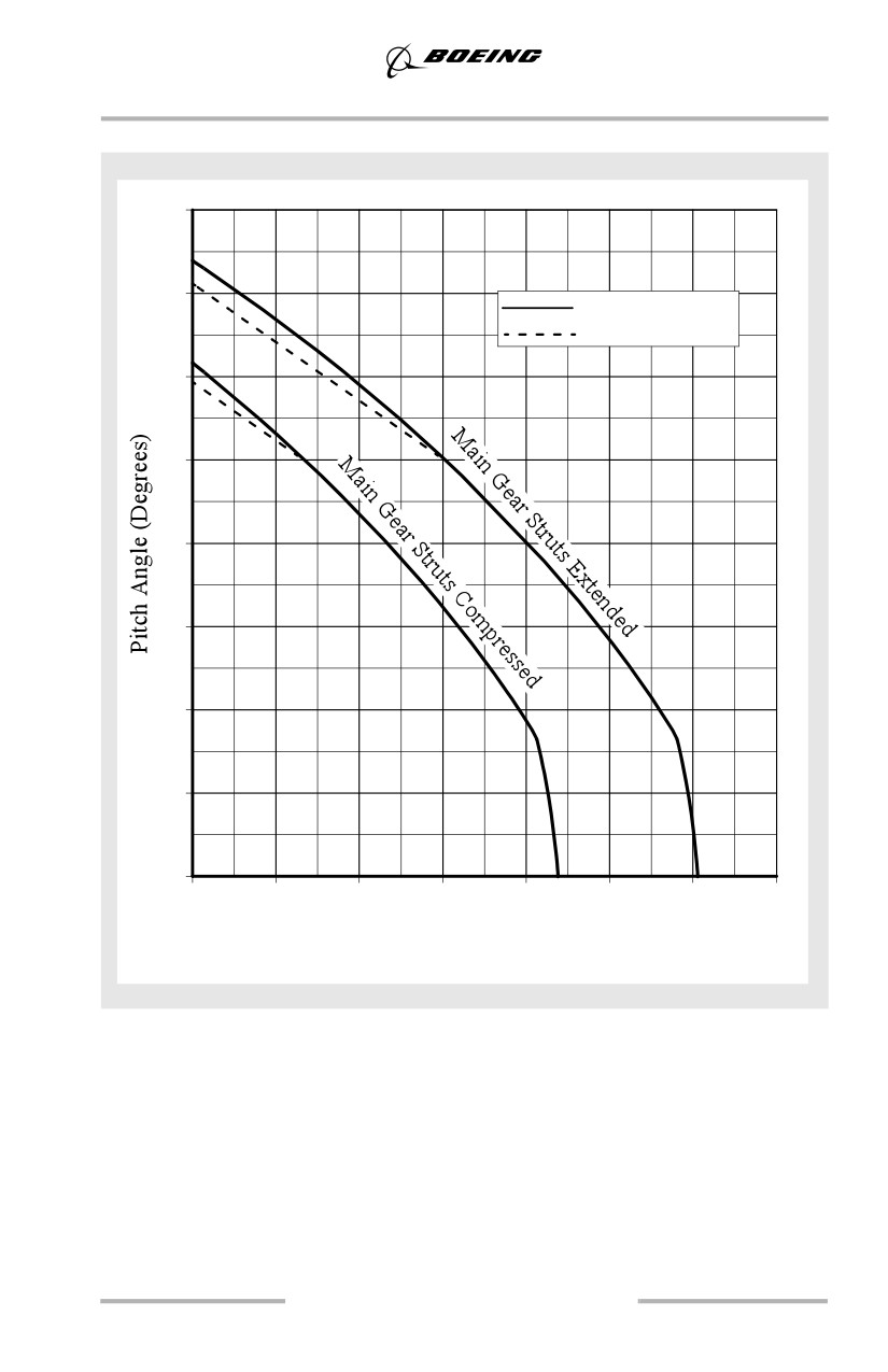
Landing
737-700
16
14
Aft Body
Aft Drain Mast
12
10
8
6
4
2
0
0
10
20
30
40
50
60
70
(0)
(25)
(51)
(76)
(102)
(127)
(152)
(178)
Clearance - inches (cm)
6.17