Boeing 737 - 600/700/800/900. Flight Crew Training Manual (1999 year) - page 8
Maneuvers
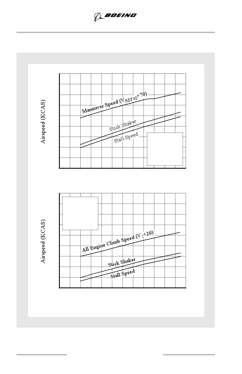
Stick Shaker and Stall Speeds
737-900
240
200
160
Flaps Up
Gear Up
120
10,000 Ft
Idle Thrust
Forward CG
80
60
80
100
120
140
160
180
(27.2)
(36.4)
(45.5)
(54.5)
(63.6)
(72.7)
(81.6)
Gross Weight - 1000 lbs (Kgs)
Flaps 5
240
Gear Up
10,000 Ft
Idle Thrust
200
Forward CG
160
120
80
60
80
100
120
140
160
180
(27.2)
(36.4)
(45.5)
(54.5)
(63.6)
(72.7)
(81.6)
Gross Weight - 1000 lbs (Kgs)
7.18
Maneuvers
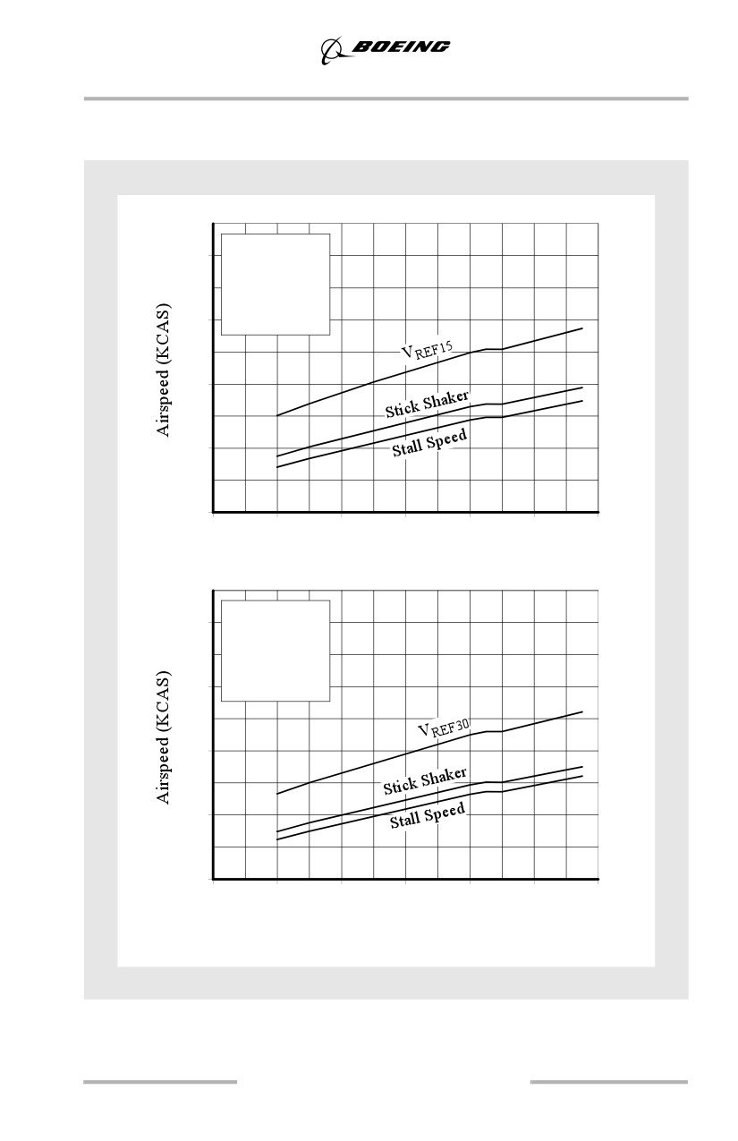
Stick Shaker and Stall Speeds
737-900
Flaps 15
220
Gear Down
10,000 Ft
Idle Thrust
180
Forward CG
140
100
60
60
80
100
120
140
160
180
(27.2)
(36.4)
(45.5)
(54.5)
(63.6)
(72.7)
(81.6)
Gross Weight - 1000 lbs (Kgs)
Flaps 30
220
Gear Down
10,000 Ft
Idle Thrust
180
Forward CG
140
100
60
60
80
100
120
140
160
180
(27.2)
(36.4)
(45.5)
(54.5)
(63.6)
(72.7)
(81.6)
Gross Weight - 1000 lbs (Kgs)
7.19
Maneuvers
Recovery from a Fully Developed Stall
An airplane may be stalled in any attitude (nose high, nose low, high angle of
bank) or any airspeed (turning, accelerated stall). It is not always intuitively
obvious that the airplane is stalled.
An airplane stall is characterized by any one (or a combination) of the following
conditions:
• buffeting, which could be heavy
• lack of pitch authority
• lack of roll control
• inability to arrest descent rate.
These conditions are usually accompanied by a continuous stall warning. A stall
must not be confused with the stall warning that alerts the pilot to an approaching
stall. Recovery from an approach to a stall is not the same as recovery from an
actual stall. An approach to a stall is a controlled flight maneuver; a stall is an
out-of-control, but recoverable, condition.
Note: Anytime the airplane enters a fully developed stall, the autopilot and
autothrottle should be disconnected.
To recover from a stall, angle of attack must be reduced below the stalling angle.
Nose down pitch control must be applied and maintained until the wings are
unstalled. Application of forward control column (as much as full forward may be
required) and the use of some nose-down stabilizer trim should provide sufficient
elevator control to produce a nose-down pitch rate. It may be difficult to know
how much stabilizer trim to use, and care must be taken to avoid using too much
trim. Pilots should not fly the airplane using stabilizer trim, and should stop
trimming nose down when they feel the g force on the airplane lessen or the
required elevator force lessen.
Under certain conditions, on airplanes with underwing-mounted engines, it may
be necessary to reduce thrust in order to prevent the angle of attack from
continuing to increase. Once the wing is unstalled, upset recovery actions may be
taken and thrust reapplied as needed.
If normal pitch control inputs do not stop an increasing pitch rate in a nose high
situation, rolling the airplane to a bank angle that starts the nose down may be
effective. Bank angles of about 45°, up to a maximum of 60°, could be needed.
Normal roll controls - up to full deflection of ailerons and spoilers - may be used.
Unloading the wing by maintaining continuous nose-down elevator pressure
keeps the wing angle of attack as low as possible, making the normal roll controls
as effective as possible.
7.20
Maneuvers
Finally, if normal pitch control then roll control is ineffective, careful rudder input
in the direction of the desired roll may be required to initiate a rolling maneuver
recovery.
WARNING: Only a small amount of rudder is needed. Too much rudder
applied too quickly or held too long may result in loss of lateral
and directional control.
Steep Turns
The objective of the steep turn maneuver is to familiarize the pilot with airplane
handling characteristics beyond 35° of bank and improve the instrument cross
check. During training, 45° of bank is used for this maneuver. It is not intended
that the pilot should ever be required to bank greater than 25° to 30° in any normal
or non-normal condition.
Note: Stabilizer trim is not recommended during the steep turn maneuver
because of increased workload during roll out.
Entry
Stabilize airspeed at 250 knots on heading and altitude. Use a normal turn entry.
An increase in pitch is required as the bank angle is increased to maintain constant
altitude. An increase in thrust is required to maintain constant airspeed.
During Turn
Pitch and thrust control are the same as for a normal turn; however, larger pitch
adjustments are required for a given altitude deviation. Trimming during the
maneuver is not recommended. Varying the angle of bank while turning makes
pitch control more difficult. If altitude loss becomes excessive, reduce the angle
of bank as needed to regain positive pitch control.
Smooth and positive control is required. A rapid instrument scan is required to
detect deviations early enough to be corrected by small adjustments.
Attitude Indicator
The attitude indicator is reliable for accurate pitch and bank information
throughout the turn. Precession error does not exist because the IRS is the source
of attitude information.
Vertical Speed Indicator
IRS vertical speed indications are reliable during the turn.
Altimeter
Crosscheck the direction and rate of change, and make smooth minor adjustments
to the pitch attitude for corrections.
7.21
Maneuvers
Airspeed
Airspeed changes very slowly because of small changes in thrust and drag.
Anticipate thrust changes and apply them at the first indication of change on the
airspeed indicator or speed tape (as installed). An increase in thrust is required as
bank angle increases.
Rollout
Roll out at the same rate as used during normal turns. Normally rollout should
begin 15° to 20° prior to the desired heading. A decrease in pitch is required as the
bank angle is decreased to maintain constant altitude. A decrease in thrust is
required to maintain constant airspeed.
Terrain Avoidance
The Ground Proximity Warning System (GPWS) PULL UP Warning occurs when
an unsafe distance or closure rate is detected with terrain below the airplane. The
Look-ahead terrain alerting (as installed) also provides an aural warning when an
unsafe distance is detected from terrain ahead of the airplane. Immediately
accomplish the Terrain Avoidance maneuver found in the non-normal maneuvers
section in the QRH.
Do not attempt to engage the autopilot and/or autothrottle until terrain clearance
is assured.
Traffic Alert and Collision Avoidance System (TCAS)
TCAS is designed to enhance crew awareness of nearby traffic and issue
advisories for timely visual acquisition or appropriate vertical flight path
maneuvers to avoid potential collisions. It is intended as a backup to visual
collision avoidance, application of right-of-way rules and ATC separation.
Use of TA/RA, TA Only, and Transponder Only Modes
TCAS operation should be initiated just before takeoff and continued until just
after landing. Whenever practical, the system should be operated in the TA/RA
mode to maximize system benefits. Operations in the Traffic Advisory (TA) Only
or TCAS Off (Transponder Only) modes, to prevent nuisance advisories and
display clutter, should be in accordance with operator policy.
The responsibility for avoiding collisions still remains with the flight crew and
ATC. Pilots should not become preoccupied with TCAS advisories and displays
at the expense of basic airplane control, normal visual lookout and other crew
duties.
7.22
Maneuvers
Traffic Advisory (TA)
A Traffic Advisory (TA) occurs when nearby traffic meets system minimum
separation criteria, and is indicated aurally and visually on the TCAS traffic
display. A goal of the TA is to alert the pilot of the possibility of an RA. If a TA is
received, immediately accomplish the Traffic Avoidance maneuver in the QRH.
Maneuvers based solely on a TA may result in reduced separation and are not
recommended.
The TA ONLY mode may be appropriate under the following circumstances:
• during takeoff toward known nearby traffic (in visual contact) which
would cause an unwanted RA during initial climb
• during closely spaced parallel runway approaches
• when flying in known close proximity to other airplanes
• in circumstances identified by the operator as having a verified and
significant potential for unwanted or undesirable RAs
• engine out operation.
Resolution Advisory (RA)
When TCAS determines that separation from approaching traffic may not be
sufficient, TCAS issues a Resolution Advisory (RA) aural warning and a pitch
command. Maneuvering is required if any portion of the airplane symbol is within
the red region on the attitude indicator. Flight crews should follow RA commands
using established procedures unless doing so would jeopardize the safe operation
of the airplane or positive visual contact confirms that there is a safer course of
action. If a RA is received, immediately accomplish the Traffic Avoidance
maneuver in the QRH.
Resolution advisories are known to occur more frequently at locations where
traffic frequently converges (e.g. waypoints). This is especially true in RVSM
airspace. Climb or descent profiles should not be modified in anticipation of
avoiding an RA unless specifically requested by ATC.
RA maneuvers require only small pitch attitude changes which should be
accomplished smoothly and without delay. Properly executed, the RA maneuver
is mild and does not require large or abrupt control movements. Remember that
the passengers and flight attendants may not all be seated during this maneuver.
The flight director is not affected by TCAS guidance. Therefore, when complying
with an RA, flight director commands may be followed only if they result in a
vertical speed that satisfies the RA command.
During the RA maneuver, the aircrew attempts to establish visual contact with the
target. However, visual perception of the encounter can be misleading,
particularly at night. The traffic acquired visually may not be the same traffic
causing the RA.
7.23
Maneuvers
Pilots should maintain situational awareness since TCAS may issue RAs in
conflict with terrain considerations, such as during approaches into rising terrain
or during an obstacle limited climb. Continue to follow the planned lateral flight
path unless visual contact with the conflicting traffic requires other action.
Windshear, GPWS, and stall warnings take precedence over TCAS advisories.
Stick shaker must be respected at all times. Complying with RAs may result in
brief exceedance of altitude and/or placard limits. However, even at the limits of
the operating envelope, in most cases sufficient performance is available to safely
maneuver the airplane. Smoothly and expeditiously return to appropriate altitudes
and speeds when clear of conflict. Maneuvering opposite to an RA command is
not recommended since TCAS may be coordinating maneuvers with other
airplanes.
Upset Recovery
For detailed information regarding the nature of upsets, aerodynamic principles,
recommended training and other related information, refer to the Airplane Upset
Recovery Training Aid available through your operator.
An upset can generally be defined as unintentionally exceeding the following
conditions:
• pitch attitude greater than 25 degrees nose up, or
• pitch attitude greater than 10 degrees nose down, or
• bank angle greater than 45 degrees, or
• within above parameters but flying at airspeeds inappropriate for the
conditions.
General
Though flight crews in line operation rarely, if ever, encounter an upset situation,
understanding how to apply aerodynamic fundamentals in such a situation helps
them control the airplane. Several techniques are available for recovering from an
upset. In most situations, if a technique is effective, it is not recommended that
pilots use additional techniques. Several of these techniques are discussed in the
example scenarios below:
• stall recovery
• nose high, wings level
• nose low, wings level
• high bank angles
• nose high, high bank angles
• nose low, high bank angles
7.24
Maneuvers
Stall Recovery
In all upset situations, it is necessary to recover from a stall before applying any
other recovery actions. A stall may exist at any attitude and may be recognized by
continuous stick shaker activation accompanied by one or more of the following:
• buffeting which could be heavy at times
• lack of pitch authority and/or roll control
• inability to arrest descent rate.
If the airplane is stalled, recovery from the stall must be accomplished first by
applying and maintaining nose down elevator until stall recovery is complete and
stick shaker activation ceases. Under certain conditions, it may be necessary to
reduce some thrust in order to prevent the angle of attack from continuing to
increase. Once stall recovery is complete, upset recovery actions may be taken and
thrust reapplied as needed.
Nose High, Wings Level
In a situation where the airplane pitch attitude is unintentionally more than 25
degrees nose high and increasing, the airspeed is decreasing rapidly. As airspeed
decreases, the pilot's ability to maneuver the airplane also decreases. If the
stabilizer trim setting is nose up, as for slow-speed flight, it partially reduces the
nose-down authority of the elevator. Further complicating this situation, as the
airspeed decreases, the pilot could intuitively make a large thrust increase. This
causes an additional pitch up. At full thrust settings and very low airspeeds, the
elevator, working in opposition to the stabilizer, has limited control to reduce the
pitch attitude.
In this situation the pilot should trade altitude for airspeed, and maneuver the
airplane's flight path back toward the horizon. This is accomplished by the input
of up to full nose-down elevator and the use of some nose-down stabilizer trim.
These actions should provide sufficient elevator control power to produce a
nose-down pitch rate. It may be difficult to know how much stabilizer trim to use,
and care must be taken to avoid using too much trim. Pilots should not fly the
airplane using stabilizer trim, and should stop trimming nose down when they feel
the g force on the airplane lessen or the required elevator force lessen. This use of
stabilizer trim may correct an out-of-trim airplane and solve a less-critical
problem before the pilot must apply further recovery measures. Because a large
nose-down pitch rate results in a condition of less than 1 g, at this point the pitch
rate should be controlled by modifying control inputs to maintain between 0 to 1
g. If altitude permits, flight tests have determined that an effective way to achieve
a nose-down pitch rate is to reduce some thrust.
7.25
Maneuvers
If normal pitch control inputs do not stop an increasing pitch rate, rolling the
airplane to a bank angle that starts the nose down should work. Bank angles of
about 45 degrees, up to a maximum of 60 degrees, could be needed. Unloading the
wing by maintaining continuous nose-down elevator pressure keeps the wing
angle of attack as low as possible, making the normal roll controls as effective as
possible. With airspeed as low as stick shaker onset, normal roll controls - up to
full deflection of ailerons and spoilers - may be used. The rolling maneuver
changes the pitch rate into a turning maneuver, allowing the pitch to decrease.
Finally, if normal pitch control then roll control is ineffective, careful rudder input
in the direction of the desired roll may be required to induce a rolling maneuver
for recovery.
Only a small amount of rudder is needed. Too much rudder applied too quickly or
held too long may result in loss of lateral and directional control. Because of the
low energy condition, pilots should exercise caution when applying rudder.
The reduced pitch attitude allows airspeed to increase, thereby improving elevator
and aileron control effectiveness. After the pitch attitude and airspeed return to a
desired range the pilot can reduce angle of bank with normal lateral flight controls
and return the airplane to normal flight.
Nose Low, Wings Level
In a situation where the airplane pitch attitude is unintentionally more than 10
degrees nose low and going lower, the airspeed is increasing rapidly. A pilot
would likely reduce thrust and extend the speedbrakes. Thrust reduction causes an
additional nose-down pitching moment. Speedbrake extension causes a nose-up
pitching moment, an increase in drag, and a decrease in lift for the same angle of
attack. At airspeeds well above VMO/MMO, the ability to command a nose-up
pitch rate with elevator may be reduced because of the extreme aerodynamic loads
on the elevator.
Again, it is necessary to maneuver the airplane's flight path back toward the
horizon. At moderate pitch attitudes, applying nose-up elevator, reducing thrust,
and extending speedbrakes, if necessary, changes the pitch attitude to a desired
range. At extremely low pitch attitudes and high airspeeds (well above
VMO/MMO), nose-up elevator and nose-up trim may be required to establish a
nose-up pitch rate.
High Bank Angles
A high bank angle is one beyond that necessary for normal flight. Though the bank
angle for an upset has been defined as unintentionally more than 45 degrees, it is
possible to experience bank angles greater than 90 degrees.
7.26
Maneuvers
Any time the airplane is not in “zero-angle-of-bank” flight, lift created by the
wings is not being fully applied against gravity, and more than 1 g is required for
level flight. At bank angles greater than 67 degrees, level flight cannot be
maintained within AFM load factor limits. In high bank angle increasing airspeed
situations, the primary objective is to maneuver the lift of the airplane to directly
oppose the force of gravity by rolling (in the shortest direction) to wings level.
Applying nose-up elevator at bank angles above 60 degrees causes no appreciable
change in pitch attitude and may exceed normal structure load limits as well as the
wing angle of attack for stall. The closer the lift vector is to vertical (wings level),
the more effective the applied g is in recovering the airplane.
A smooth application of up to full lateral control should provide enough roll
control power to establish a very positive recovery roll rate. If full roll control
application is not satisfactory, it may even be necessary to apply some rudder in
the direction of the desired roll.
Only a small amount of rudder is needed. Too much rudder applied too quickly or
held too long may result in loss of lateral and directional control or structural
failure.
Nose High, High Bank Angles
A nose high, high angle of bank upset requires deliberate flight control inputs. A
large bank angle is helpful in reducing excessively high pitch attitudes. The pilot
must apply nose-down elevator and adjust the bank angle to achieve the desired
rate of pitch reduction while considering energy management. Once the pitch
attitude has been reduced to the desired level, it is necessary only to reduce the
bank angle, ensure that sufficient airspeed has been achieved, and return the
airplane to level flight.
Nose Low, High Bank Angles
The nose low, high angle of bank upset requires prompt action by the pilot as
altitude is rapidly being exchanged for airspeed. Even if the airplane is at a high
enough altitude that ground impact is not an immediate concern, airspeed can
rapidly increase beyond airplane design limits. Simultaneous application of roll
and adjustment of thrust may be necessary. It may be necessary to apply
nose-down elevator to limit the amount of lift, which will be acting toward the
ground if the bank angle exceeds 90 degrees. This also reduces wing angle of
attack to improve roll capability. Full aileron and spoiler input should be used if
necessary to smoothly establish a recovery roll rate toward the nearest horizon. It
is important to not increase g force or use nose-up elevator or stabilizer until
approaching wings level. The pilot should also extend the speedbrakes as needed.
7.27
Maneuvers
Upset Recovery Techniques
It is possible to consolidate and incorporate recovery techniques into two basic
scenarios, nose high and nose low, and to acknowledge the potential for high bank
angles in each scenario described above. Other crew actions such as recognizing
the upset, reducing automation, and completing the recovery are included in these
techniques. The recommended techniques provide a logical progression for
recovering an airplane.
If an upset situation is recognized, immediately accomplish the Upset Recovery
maneuver found in the non-normal maneuvers section in the QRH.
Windshear
General
Improper or ineffective vertical flight path control has been one of the primary
factors in many cases of flight into terrain. Low altitude windshear encounters are
especially significant because windshear can place the crew in a situation which
requires the maximum performance capability of the airplane. Windshear
encounters near the ground are the most threatening because there is very little
time or altitude to respond to and recover from an encounter.
Airplane Performance in Windshear
Knowledge of how windshear affects airplane performance can be essential to the
successful application of the proper vertical flight path control techniques during
a windshear encounter.
The wind component is mostly horizontal at altitudes below 500 feet. Horizontal
windshear may improve or degrade vertical flight path performance. Windshear
that improves performance is first indicated in the flight deck by an increasing
airspeed. This type of windshear may be a precursor of a shear that decreases
airspeed and degrades vertical flight path performance.
Airspeed decreases if the tailwind increases, or headwind decreases, faster than
the airplane is accelerating. As the airspeed decreases, the airplane normally tends
to pitch down to maintain or regain the in-trim speed. The magnitude of pitch
change is a function of the encountered airspeed change. If the pilot attempts to
regain lost airspeed by lowering the nose, the combination of decreasing airspeed
and decreasing pitch attitude produces a high rate of descent. Unless this is
countered by the pilot, a critical flight path control situation may develop very
rapidly. As little as 5 seconds may be available to recognize and react to a
degrading vertical flight path.
7.28
Maneuvers
In critical low altitude situations, trade airspeed for altitude, if possible. An
increase in pitch attitude, even though the airspeed may be decreasing, increases
the lifting force and improves the flight path angle. Proper pitch control, combined
with maximum available thrust, utilizes the total airplane performance capability.
The crew must be aware of the normal values of airspeed, altitude, rate of climb,
pitch attitude and control column forces. Unusual control column force may be
required to maintain or increase pitch attitude when airspeed is below the in-trim
speed. If significant changes in airspeed occur and unusual control forces are
required, the crew should be alerted to a possible windshear encounter and be
prepared to take action.
Avoidance, Precautions and Recovery
Crew actions are divided into three areas: Avoidance, Precautions and Recovery.
For more information on avoidance and precautions, see the Windshear
supplementary procedure in Volume 1 of the FCOM. For specific crew actions for
recovery, see the Non-Normal Maneuvers section in the QRH.
7.29
Maneuvers
Intentionally
Blank
7.30
Non-Normal Operations
Chapter 8
Table of Contents
Section TOC
8.TOC Non-Normal Operations-Table of Contents
Preface
8.1
Non-Normal Situation Guidelines
8.1
Troubleshooting
8.2
Approach and Landing
8.3
Landing at the Nearest Suitable Airport
8.3
Air Systems
8.4
Cabin Altitude Warning
8.4
Ditching
8.5
Send Distress Signals
8.5
Advise Crew and Passengers
8.5
Fuel Burn-Off
8.5
Passenger Cabin Preparation
8.5
Ditching Final
8.5
Initiate Evacuation
8.6
Electrical
8.6
Approach and Landing on Standby Power
8.6
Engines, APU
8.6
Engine Failure vs Engine Fire After Takeoff
8.6
Engine Tailpipe Fire
8.7
Loss of Engine Thrust Control
8.7
Loss of Thrust on Both Engines
8.8
Engine Severe Damage Accompanied by High Vibration
8.8
Recommended Technique for an In-Flight Engine Shutdown
8.9
8.TOC.1
Non-Normal Operations -
Table of Contents
Evacuation
8.9
Method of Evacuation
8.10
Discharging Fire Bottles during an Evacuation
8.10
Flight Controls
8.11
Leading Edge or Trailing Edge Device Malfunctions
8.11
Flap Extension using the Alternate System
8.13
Jammed or Restricted Flight Controls
8.13
Stabilizer Trim Inoperative
8.15
Runaway Stabilizer
8.16
Manual Stabilizer Trim
8.16
Standby Rudder On (As Installed)
8.17
Flight Instruments, Displays
8.17
Airspeed Unreliable
8.17
Fuel
8.18
Fuel Balance
8.18
Fuel Leak
8.19
Low Fuel
8.20
Hydraulics
8.20
Hydraulic System(s) Inoperative - Landing
8.20
Landing Gear
8.22
Tire Failure during or after Takeoff
8.22
Landing on a Flat Tire
8.22
Partial or Gear Up Landing
8.23
Overspeed
8.25
Tail Strike
8.26
Takeoff Risk Factors
8.26
8.TOC.2
Non-Normal Operations -
Table of Contents
Landing Risk Factors
8.27
Wheel Well Fire
8.29
Windows
8.30
Window Damage
8.30
Flight with the Side Window(s) Open
8.30
Situations Beyond the Scope of Non-Normal Checklists
8.30
Basic Aerodynamics and Systems Knowledge
8.31
Flight Path Control
8.32
Recall Checklists
8.32
Communications
8.33
Damage Assessment and Airplane Handling Evaluation
8.33
Landing Airport
8.34
8.TOC.3
Non-Normal Operations -
Table of Contents
Intentionally
Blank
8.TOC.4
Non-Normal Operations
Chapter 8
Preface
This chapter describes pilot techniques associated with accomplishing selected
Non-Normal Checklists (NNCs) and provides guidance for situations beyond the
scope of NNCs. Aircrews are expected to accomplish NNCs listed in the QRH.
These checklists ensure maximum safety until appropriate actions are completed
and a safe landing is accomplished. Techniques discussed in this chapter minimize
workload, improve crew coordination, enhance safety, and provide a basis for
standardization. A thorough review of the QRH section CI.2, (Checklist
Introduction, Non-Normal Checklists), is an important prerequisite to
understanding this chapter.
Non-Normal Situation Guidelines
When a non-normal situation occurs, the following guidelines apply:
• NON-NORMAL RECOGNITION: The crewmember recognizing the
malfunction calls it out clearly and precisely
• MAINTAIN AIRPLANE CONTROL: It is mandatory that the Pilot
Flying (PF) fly the airplane while the Pilot Monitoring (PM)
accomplishes the NNC. Maximum use of the autoflight system is
recommended to reduce crew workload
• ANALYZE THE SITUATION: NNCs should be accomplished only after
the malfunctioning system has been positively identified
Note: Pilots should don oxygen masks and establish communications
anytime oxygen deprivation or air contamination is suspected, even
though an associated warning has not occurred.
8.1
Non-Normal Operations
• TAKE THE PROPER ACTION: Although many in-flight non-normal
situations require immediate corrective action, difficulties can be
compounded by the rate the PF issues commands and the speed of
execution by the PM. Commands must be clear and concise, allowing
time for acknowledgment of each command prior to issuing further
commands. The PF must exercise positive control by allowing time for
acknowledgment and execution. The other crewmembers must be certain
their reports to the PF are clear and concise, neither exaggerating nor
understating the nature of the non-normal situation. This eliminates
confusion and ensures efficient, effective, and expeditious handling of the
non-normal situation
• EVALUATE THE NEED TO LAND: If the NNC directs the crew to land
at the nearest suitable airport, or if the situation is so identified in the
QRH section CI.2, (Checklist Introduction, Non-Normal Checklists),
diversion to the nearest airport where a safe landing can be accomplished
is required. If the NNC or the Checklist Introduction do not direct landing
at the nearest suitable airport, the pilot must determine if continued flight
to destination may compromise safety.
Troubleshooting
Troubleshooting can be defined as taking steps beyond the published checklist in
an effort to improve or correct a non-normal condition. Examples of this are:
• attempting to reset a system, or cycling a circuit breaker when not
prescribed by the NNC
• using maintenance-level information to dictate crew actions
• use of switches and controls intended only for maintenance.
Troubleshooting is rarely helpful and has caused further loss of system function
or failure, and in some cases, accidents and incidents. The crew should consider
additional actions beyond the checklist only when completion of the published
checklist steps clearly result in an unacceptable situation. In the case of airplane
controllability problems when a safe landing is considered unlikely, airplane
handling evaluations with gear, flaps or speedbrakes extended may be appropriate.
Also, attempting to free jammed flight controls should only be attempted if the
airplane cannot be safely landed with the existing condition and then, according
to the NNC to the extent possible.
Crew distraction, caused by preoccupation with troubleshooting, has been a key
factor in fuel starvation and CFIT accidents. Boeing recommends completion of
the NNC as published whenever possible, in particular for flight control
malfunctions that are addressed by a NNC. Guidance for situations beyond the
scope of the non-normal checklist is provided later in this chapter.
8.2
Non-Normal Operations
Approach and Landing
When a non-normal situation occurs, a rushed approach can often complicate the
situation. Unless circumstances require an immediate landing, complete all
corrective actions before beginning the final approach.
For some non-normal conditions, the possibility of higher airspeed on approach,
longer landing distance, a different flare picture or a different landing technique
should be considered.
Plan an extended straight-in approach with time allocated for the completion of
any lengthy NNC steps such as the use of alternate flap or landing gear extension
systems. Arm autobrakes and speedbrakes unless precluded by the NNC.
Note: The use of autobrakes is recommended because maximum autobraking
may be more effective than maximum manual braking due to timely
application upon touchdown and symmetrical braking. However, the
Advisory Information in the PI chapter of the QRH provides Non-normal
Configuration Landing Distance data based upon the use of maximum
manual braking. When used properly, maximum manual braking provides
the shortest stopping distance.
Fly a normal glide path and attempt to land in the normal touchdown zone. After
landing, use available deceleration measures to bring the airplane to a complete
stop on the runway. The captain must determine if an immediate passenger
evacuation should be accomplished or if the airplane can be safely taxied off the
runway.
Landing at the Nearest Suitable Airport
“Plan to land at the nearest suitable airport” is a phrase used in the QRH. This
section explains the basis for that statement and how it is applied.
In a non-normal situation, the pilot-in-command, having the authority and
responsibility for operation and safety of the flight, must make the decision to
continue the flight as planned or divert. In an emergency situation, this authority
may include necessary deviations from any regulation to meet the emergency. In
all cases, the pilot-in-command is expected to take a safe course of action.
The QRH assists flight crews in the decision making process by indicating those
situations where “landing at the nearest suitable airport” is required. These
situations are described in the Checklist Introduction or the individual NNC.
The regulations regarding an engine failure are specific. Most regulatory agencies
specify that the pilot-in-command of a twin engine airplane that has an engine
failure or engine shutdown shall land at the nearest suitable airport at which a safe
landing can be made.
8.3
Non-Normal Operations
A suitable airport is defined by the operating authority for the operator based on
guidance material, but in general must have adequate facilities and meet certain
minimum weather and field conditions. If required to divert to the nearest suitable
airport (twin engine airplanes with an engine failure), the guidance material also
typically specifies that the pilot should select the nearest suitable airport “in point
of time” or “in terms of time.” In selecting the nearest suitable airport, the
pilot-in-command should consider the suitability of nearby airports in terms of
facilities and weather and their proximity to the airplane position. The
pilot-in-command may determine, based on the nature of the situation and an
examination of the relevant factors, that the safest course of action is to divert to
a more distant airport than the nearest airport. For example, there is not necessarily
a requirement to spiral down to the airport nearest the airplane's present position
if, in the judgment of the pilot-in-command, it would require equal or less time to
continue to another nearby airport.
For persistent smoke or a fire which cannot positively be confirmed to be
completely extinguished, the safest course of action typically requires the earliest
possible descent, landing and passenger evacuation. This may dictate landing at
the nearest airport appropriate for the airplane type, rather than at the nearest
suitable airport normally used for the route segment where the incident occurs.
Air Systems
Cabin Altitude Warning
There have been several reports of cabin altitude warning alerts caused by
improperly configured engine bleed air and air conditioning pack switches. This
condition is often the result of crews failing to reconfigure switches following a
no engine bleed takeoff. Additionally, there have been reports of crews delaying
their response to the cabin altitude warning alert because it was confused with the
takeoff configuration warning horn.
In order to address the problem of incorrectly positioning switches that affect
pressurization, the normal takeoff procedure has been modified to direct the crew
to set or verify the correct position of the engine bleed air and air conditioning
pack switches after flap retraction is complete. Engine bleeds and air conditioning
packs have also been included as specific items in the After Takeoff normal
checklist. Additionally, when doing a no engine bleed takeoff, reference to the No
Engine Bleed Takeoff supplementary procedure, in conjunction with good crew
coordination, reduces the possibility of crew errors.
8.4
Non-Normal Operations
Confusion between the cabin altitude warning horn and the takeoff configuration
warning horn can be resolved if the crew remembers that the takeoff configuration
warning horn is only armed when the airplane is on the ground. If this horn is
activated in flight, it indicates that the cabin altitude has reached 10,000 feet. In
this case, the crew should immediately initiate the Cabin Altitude Warning or
Rapid Depressurization NNC.
Ditching
Send Distress Signals
Transmit Mayday, current position, course, speed, altitude, situation, intention,
time and position of intended touchdown, and type of airplane using existing
air-to-ground frequency. Set transponder code 7700 and, if practical, determine
the course to the nearest ship or landfall.
Advise Crew and Passengers
Alert the crew and the passengers to prepare for ditching. Assign life raft positions
(as installed) and order all loose equipment in the airplane secured. Put on life
vests, shoulder harnesses, and seat belts. Do not inflate life vests until after exiting
the airplane.
Fuel Burn-Off
Consider burning off fuel prior to ditching, if the situation permits. This provides
greater buoyancy and a lower approach speed. However, do not reduce fuel to a
critical amount, as ditching with engine power available improves ability to
properly control touchdown.
Passenger Cabin Preparation
Confer with cabin personnel either by interphone or by having them report to the
flight deck in person to ensure passenger cabin preparations for ditching are
complete.
Ditching Final
Transmit final position. Select flaps 40 or landing flaps appropriate for the existing
conditions.
Advise the cabin crew of imminent touchdown. On final approach announce
ditching is imminent and advise crew and passengers to brace for impact.
Maintain airspeed at VREF. Maintain 200 to 300 fpm rate of descent. Plan to
touchdown on the windward side and parallel to the waves or swells, if possible.
To accomplish the flare and touchdown, rotate smoothly to touchdown attitude of
10° to 12°. Maintain airspeed and rate of descent with thrust.
8.5
Non-Normal Operations
Initiate Evacuation
After the airplane has come to rest, proceed to assigned ditching stations and
evacuate as soon as possible, ensuring all passengers are out of the airplane.
Deploy slides/rafts. Be careful not to rip or puncture the slides/rafts. Avoid drifting
into or under parts of the airplane. Remain clear of fuel-saturated water.
Electrical
Approach and Landing on Standby Power
The probability of a total and unrecoverable AC power failure is remote. Because
of system design, a NNC for accomplishing an approach and landing on standby
power is not required. However, some regulatory agencies require pilots to train
for this condition. During training, or in the unlikely event that a landing must be
made on standby power, the following guidelines should be considered.
Complete all applicable NNCs and approach preparations. Manual pressurization
control and manual stabilizer trim are required. The left navigation radios and
communication radio are operable on standby power. Use right ignition. On some
airplanes, the captain's electronic flight instruments and left FMC are available.
Note: Refer to Volume 2, Chapter 6 of the FCOM for a list of significant
equipment powered by standby power.
Fly the approach on speed. Only partial anti-skid is available so excess approach
airspeed is undesirable. Brake with caution. The flap position indicator is
inoperative. Auto brakes and auto speedbrakes are not available. Reverse thrust is
available.
Engines, APU
Engine Failure vs Engine Fire After Takeoff
The NNC for an engine failure is normally accomplished after the flaps have been
retracted and conditions permit.
In case of an engine fire, when the airplane is under control, the gear has been
retracted, and a safe altitude has been attained (minimum 400 feet AGL)
accomplish the NNC recall items. Due to asymmetric thrust considerations,
Boeing recommends that the PF retard the affected thrust lever after the PM
confirms that the PF has identified the correct engine. Reference items should be
accomplished on a non-interfering basis with other normal duties after the flaps
have been retracted and conditions permit.
8.6
Non-Normal Operations
Engine Tailpipe Fire
Engine tailpipe fires are typically caused by engine control malfunctions that
result in the ignition of pooled fuel. These fires can be damaging to the engine and
have caused unplanned passenger evacuations.
If a tailpipe fire is reported, the crew should accomplish the NNC without delay.
Flight crews should consider the following when dealing with this situation:
• motoring the engine is the primary means of extinguishing the fire
• to prevent an inappropriate evacuation, flight attendants should be
notified without significant delay
• communications with ramp personnel and the tower are important to
determine the status of the tailpipe fire and to request fire extinguishing
assistance
• the engine fire checklist is inappropriate because the engine fire
extinguishing agent is not effective against a fire inside the tailpipe.
Loss of Engine Thrust Control
All turbo fan engines are susceptible to this malfunction whether engine control is
hydro-mechanical, hydro-mechanical with supervisory electronics (e.g. PMC) or
Full Authority Digital Engine Control (FADEC). Engine response to a loss of
control varies from engine to engine. Malfunctions have occurred in-flight and on
the ground. The major challenge the flight crew faces when responding to this
malfunction is recognizing the condition and determining which engine has
malfunctioned. This condition can occur during any phase of flight.
Failure of engine or fuel control system components, or loss of thrust lever
position feedback has caused loss of engine thrust control. Control loss may not
be immediately evident since many engines fail to some fixed RPM or thrust lever
condition. This fixed RPM or thrust lever condition may be very near the
commanded thrust level and therefore difficult to recognize until the flight crew
attempts to change thrust with the thrust lever. Other engine responses include:
shutdown, operation at low RPM, or thrust at the last valid thrust lever setting (in
the case of a thrust lever feedback fault) depending on altitude or air/ground logic.
In all cases, the affected engine does not respond to thrust lever movement.
The Engine Limit/Surge/Stall NNC is written to include this malfunction. Since
recognition may be difficult, if a loss of engine control is suspected, the flight crew
should continue the takeoff or remain airborne until the Engine Limit/Surge/Stall
NNC can be accomplished. This helps with directional control and may preclude
an inadvertent shutdown of the wrong engine. In some conditions, such as during
low speed ground operations, immediate engine shutdown may be necessary to
maintain directional control.
8.7
Non-Normal Operations
Loss of Thrust on Both Engines
Dual engine failure is a situation that demands prompt action regardless of altitude
or airspeed. Accomplish recall items and establish the appropriate airspeed to
immediately attempt a windmill restart. There is a higher probability that a
windmill start will succeed if the restart attempt is made as soon as possible (or
immediately after recognizing an engine failure) to take advantage of high engine
RPM. Use of higher airspeeds and altitudes below 30,000 feet improves the
probability of a restart. Loss of thrust at higher altitudes may require descent to a
lower altitude to improve windmill starting capability.
The inflight start envelope defines the region where windmill starts were
demonstrated during certification. It should be noted that this envelope does not
define the only areas where a windmill start may be successful. The dual engine
failure NNC is written to ensure flight crews take advantage of the high RPM at
engine failure regardless of altitude or airspeed. A subsequent APU start may be
initiated as soon as practical to provide electrical power and starter assist during a
subsequent engine start attempt if the rapid restart is not successful. Initiate the
rapid restart recall procedure before attempting an APU start for the reasons
identified above.
During a rapid restart, EGT may exceed the displayed limit for one-engine starts.
During restart attempts with both engines failed, use the takeoff EGT limit. A hung
or stalled in-flight start is normally indicated by stagnant RPM and increasing
EGT. During start, engines may accelerate to idle slowly but action should not be
taken if RPM is increasing and EGT is not near or rapidly approaching the limit.
Note: When electrical power is restored, do not confuse the establishment of
APU generator power with the establishment of engine generator power at
idle RPM and advance the thrust lever prematurely.
Engine Severe Damage Accompanied by High Vibration
Certain engine failures, such as fan blade separation can cause high levels of
airframe vibration. Although the airframe vibration may seem severe to the flight
crew, it is extremely unlikely that the vibration will damage the airplane structure
or critical systems. However, the vibration should be reduced as soon as possible
by reducing airspeed and descending. As altitude and airspeed change, the
airplane may transition through various levels of vibration. In general, vibration
levels decrease as airspeed decreases, however, at a given altitude vibration may
temporarily increase or decrease as airspeed changes.
If vibration remains unacceptable, descending to a lower altitude (terrain
permitting) allows a lower airspeed and normally lower vibration levels. Vibration
will likely become imperceptible as airspeed is further reduced during approach.
8.8
Non-Normal Operations
The impact of a vibrating environment on human performance is dependent on a
number of factors, including the orientation of the vibration relative to the body.
People working in a vibrating environment may find relief by leaning forward or
backward, standing, or otherwise changing their body position.
Once airframe vibration has been reduced to acceptable levels, the crew must
evaluate the situation and determine a new course of action based on weather, fuel
remaining, and available airports.
Recommended Technique for an In-Flight Engine Shutdown
Any time an engine shutdown is required in flight, good crew coordination is
essential. Airplane incidents have turned into airplane accidents as a result of the
flight crew shutting down the incorrect engine.
When the flight path is under complete control, the crew should proceed with a
deliberate, systematic process that identifies the correct engine and ensures that
the incorrect engine is not shut down. Do not rush through the shutdown
procedure, even for a fire indication. Operators may develop their own crew
coordination techniques that meet these objectives. The following technique is an
example that could be used:
When an engine shutdown is required, the PF verbally confirms the correct engine
with the PM, then disconnects the A/T and slowly retards the thrust lever of the
engine that will be shutdown.
Coordinate activation of the start lever as follows:
• PM places a hand on and verbally identifies the start lever for the engine
that will be shutdown
• PF verbally confirms that the PM has identified the correct engine
• PF directs the PM to move the start lever to cutoff.
If the NNC requires activation of the engine fire switch, coordinate as follows:
• PM places a hand on and verbally identifies the engine fire switch for the
engine that will be shutdown
• PF verbally confirms that the PM has identified the correct engine
• PF directs the PM to pull engine fire switch.
Evacuation
If an evacuation is planned and time permits, a thorough briefing and preparation
of the crew and passengers will increase the chances of a successful evacuation.
Flight deck preparations should include a review of pertinent checklists and any
other actions to be accomplished. Appropriate use of autobrakes should be
discussed. If evacuating due to fire in windy conditions, consider positioning the
airplane so the fire is on the downwind side.
8.9
Non-Normal Operations
Notify cabin crew of possible adverse conditions at the affected exits. The
availability of various exits may differ for each situation. Crewmembers must
make the decision as to which exits are usable for the circumstances.
For unplanned evacuations, the captain needs to analyze the situation carefully
before initiating an evacuation order. Quick actions in a calm and methodical
manner will improve the chances for a successful passenger evacuation.
Method of Evacuation
When there is a need to evacuate passengers and crew, the captain has to choose
between commanding an emergency evacuation using the emergency escape
slides or less urgent means such as deplaning using stairs, jetways, or other means.
All available sources of information should be used to determine the safest course
of action including reports from the cabin crew, other aircraft, and air traffic
control. The captain must then determine the best means of passenger evacuation
by carefully considering all factors. These include, but are not limited to:
• the urgency of the situation, including the possibility of significant injury
or loss of life if a significant delay occurs
• the type of threat to the airplane, including structural damage, fire,
reported bomb on board, etc.
• the possibility of fire spreading rapidly from spilled fuel or other
flammable materials
• the extent of damage to the airplane
• the possibility of passenger injury during an emergency evacuation using
the escape slides.
If in doubt, the crew should consider an emergency evacuation using the escape
slides.
Discharging Fire Bottles during an Evacuation
The evacuation NNC specifies discharge of the engine or APU fire bottles if an
engine or APU fire warning light is illuminated. However, evacuation situations
can present possibilities regarding the potential for fire that are beyond the scope
of the NNC and may not activate an engine or APU fire warning. The crew should
consider the following when deciding whether to discharge one or more fire
bottles into the engines and/or APU:
• if an engine fire warning light is not illuminated, but a fire indication
exists or a fire is reported in or near an engine, discharge both available
fire bottles into the affected engine
• if the APU fire warning light is not illuminated, but a fire indication exists
or a fire is reported in or near the APU, discharge the APU bottle
8.10
Non-Normal Operations
• the discharged halon agent is designed to extinguish a fire and has very
little or no fire prevention capability in the engine nacelles. Halon
dissipates quickly into the atmosphere
• there is no reason to discharge the engine or APU fire bottles for
evacuations not involving fire indications existing or reported in or near
an engine or APU, e.g., cargo fire, security or bomb threat, etc.
Flight Controls
Leading Edge or Trailing Edge Device Malfunctions
Leading edge or trailing edge device malfunctions can occur during extension or
retraction. This section discusses all flaps up and partial or asymmetrical
leading/trailing edge device malfunctions for landings.
All Flaps Up Landing
The probability of both leading and trailing edge devices failing to extend is
remote. If a flaps up landing situation were to be encountered in service, the pilot
should consider the following techniques. Training to this condition should be
limited to the flight simulator.
After selecting a suitable landing airfield and prior to beginning the approach,
consider reduction of airplane gross weight (burn off fuel) to reduce touchdown
speed.
Fly a wide pattern to allow for the increased turning radius required for the higher
maneuvering speed. Establish final approximately 10 miles from the runway. This
allows time to extend the gear and decelerate to the target speed while in level
flight and complete all required checklists. Maintain no slower than flaps up
maneuvering speed until established on final. Maneuver with normal bank angles
until on final.
Final Approach
Use an ILS glide slope if available. Do not reduce the airspeed to the final
approach speed until aligned with the final approach. Before intercepting the
descent profile, decrease airspeed to command speed and maintain this speed until
the landing is assured.
The normal rate of descent on final is approximately 900 fpm due to the higher
ground speed. Final approach body attitude is approximately 1° - 2° higher than a
flaps 30 approach. Do not make a flat approach (shallow glide path angle) or aim
for the threshold of the runway. Plan touchdown at the 1,000 foot point.
8.11
Non-Normal Operations
Use manual control of thrust levers. Due to automatic speed protection,
autothrottle use may result in higher than desired speed on final. Engines will be
at low idle speed due to no flap extension. When engines are near idle RPM, time
required for engines to accelerate is longer than normal.
Note: Use of the autopilot during approach phase is acceptable. Do not autoland.
Speedbrakes are not recommended for airspeed reduction below 800 feet. If
landing is anticipated beyond the normal touch down zone, go around.
Landing
Fly the airplane onto the runway at the recommended touchdown point. Flare only
enough to achieve an acceptable reduction in the rate of descent. Do not allow the
airplane to float. Floating just above the runway surface to deplete additional
speed wastes available runway and increases the possibility of a tail strike. Do not
risk touchdown beyond the normal touchdown zone in an effort to achieve a
smooth landing.
Slight forward pressure on the control column may be required to achieve
touchdown at the desired point and to lower the nosewheel to the runway. After
lowering the nosewheel to the runway, hold forward control column pressure and
expeditiously accomplish the landing roll procedure. Full reverse thrust is
required for a longer period of time.
Use of autobrakes is recommended. Autobrake setting should be consistent with
runway length. Use manual braking if deceleration is not suitable for the desired
stopping distance.
Immediate initiation of reverse thrust at main gear touchdown (reverse thrust is
more effective at high speeds) and full reverse thrust allows the autobrake system
to reduce brake pressure to the minimum level. Less than maximum reverse thrust
increases brake energy requirements and may result in excessive brake
temperatures.
Leading Edge Flaps Transit - Landing
If an asymmetrical or skewed leading edge device condition occurs, the adjusted
VREF provides 15° bank angle maneuvering capability and allows for 15°
overshoot protection in all cases.
Do not hold the airplane off during landing flare. Floating just above the runway
surface to deplete the additional threshold speed wastes available runway and
increases the possibility of a tail strike.
Note: If the gear is retracted during a go-around and flap position is greater than
25, a landing gear configuration warning occurs.
8.12
Non-Normal Operations
Trailing Edge Flap Asymmetry - Landing
If a trailing edge flap up asymmetry occurs, full maneuvering capability exists
even if the asymmetry occurred at flaps just out of the full up position. Burn off
fuel to reduce landing weight and lower approach speed.
Fly accurate airspeeds in the landing pattern. At lesser flap settings, excess
airspeed is difficult to dissipate, especially when descending on final approach.
Pitch attitude and rate of descent on final is higher than for a normal landing.
During flare, airspeed does not bleed off as rapidly as normal.
Fly the airplane onto the runway at the recommended touchdown point. Flare only
enough to achieve an acceptable reduction in the rate of descent. Do not allow the
airplane to float. Floating just above the runway surface to deplete additional
speed wastes available runway and increases the possibility of a tail strike. Do not
risk touchdown beyond the normal touchdown zone in an effort to achieve a
smooth landing.
Note: If the gear is retracted during a go-around and flap position is greater than
25, a landing gear configuration warning occurs.
Flap Extension using the Alternate System
When extending the flaps using the alternate system, the recommended method
for setting command speed differs from the method used during normal flap
extension. Since the flaps extend more slowly when using the alternate system, it
is recommended that the crew delay setting the new command speed until the flaps
reach the selected position. This method may prevent the crew from inadvertently
getting into a low airspeed condition if attention to airspeed is diverted while
accomplishing other duties.
Jammed or Restricted Flight Controls
Although rare, jamming of the flight control system has occurred on commercial
airplanes. A jammed flight control can result from ice accumulation due to water
leaks onto cables or components, dirt accumulation, component failure such as
cable break or worn parts, improper lubrication, or foreign objects.
A flight control jam may be difficult to recognize, especially in a properly
trimmed airplane. A jam in the pitch axis may be more difficult to recognize than
a jam in other axes. In the case of the elevator, the jammed control can be masked
by trim. Some indications of a jam are:
• unexplained autopilot disconnect
• autopilot that cannot be engaged
• undershoot or overshoot of an altitude during autopilot level-off
• higher than normal control forces required during speed or configuration
changes
8.13
Non-Normal Operations
If any jammed flight control condition exists, both pilots should apply force to try
to either clear the jam or activate the override feature. There should be no concern
about damaging the flight control mechanism by applying too much force to either
clear a jammed flight control or activate an override feature. Maximum force may
result in some flight control surface movement with a jammed flight control. If the
jam clears, both pilot’s flight controls are available.
Note: If a control is jammed due to ice accumulation, the jam may clear when
moving to a warmer temperature.
Some flight controls are linked together through override features. If the jam does
not clear, activation of an override feature allows a flight control surface to be
moved independent of the jammed control. Applying force to the non-jammed
flight control activates the override feature. When enough force is applied, the
jammed control is overridden allowing the non-jammed control to operate. To
identify the non-jammed flight control, apply force to each flight control
individually. The flight control that results in the greatest airplane control is the
non-jammed control.
Note: The pilot of the non-jammed control should be the pilot flying for the
remainder of the flight.
The non-jammed control requires a normal force, plus an additional override force
to move the flight control surface. For example, if a force of 10 lbs (4 kg) is
normally required to move the surface, and 50 lbs (23 kg) of force is required to
activate the override, a total force of 60 lbs (27 kg) is required to move the control
surface while in override. Response is slower than normal with a jammed flight
control; however, sufficient response is available for airplane control and landing.
For those controls without override features, limited flight control surface
deflection occurs when considerable force is applied to the flight control. This
response is due to cable stretch and structural bending. This response may be
sufficient for airplane control and landing.
Note: There is an override feature that allows control of the ailerons or spoilers.
There is also an override feature that allows control of the elevator in the
event of a control column jam.
Trim Inputs
If a jammed flight control condition exists, use manual inputs from other control
surfaces to counter pressures and maintain a neutral flight control condition. The
following table provides trim inputs that may be used to counter jammed flight
control conditions.
8.14

Non-Normal Operations
Jammed Control Surface
Manual Trim Inputs
Elevator
Stabilizer
Aileron
Rudder*
Rudder
Aileron*
*Asymmetric engine thrust may aid roll and directional
control.
Approach and Landing
Attempt to select a runway with minimum crosswind. Complete approach
preparations early. Recheck flight control surface operation prior to landing to
determine if the malfunction still exists. Do not make abrupt thrust, speedbrake,
or configuration changes. Make small bank angle changes. On final approach, do
not reduce thrust to idle until after touchdown. Asymmetrical braking and
asymmetrical thrust reverser deployment may aid directional control on the
runway.
Note: In the event of an elevator jam, control forces will be significantly greater
than normal and control response will be slower than normal to flare the
airplane.
Go Around Procedure
If the elevator is known or suspected to be jammed, a go-around should be avoided
if at all possible. To execute a go-around with a jammed elevator, smoothly
advance throttles while maintaining pitch control with stabilizer and any available
elevator. If a go-around is required, the go-around procedure is handled in the
same manner as a normal go-around.
Stabilizer Trim Inoperative
The stabilizer trim may become inoperative for number of reasons. The most
common reason is a failed stabilizer motor. This failure mode causes a loss of
electric trim through both the autopilot and control wheel switches, but manual
trim is still available using the trim wheels. This failure mode is addressed using
the STABILIZER TRIM INOPERATIVE NNC.
8.15
Non-Normal Operations
Other, less common failure modes that are also addressed using the STABILIZER
TRIM INOPERATIVE NNC include:
• a lodged or stuck stabilizer motor. This failure mode causes a loss of
electric trim through both the autopilot and control wheel switches, but
manual trim is still available using the trim wheels by overriding autopilot
and main electric trim brake systems. The effort required to manually
rotate the trim wheels in this condition is higher than normal
• a lodged or stuck stabilizer actuator. This failure mode causes a loss of
electric trim through both the autopilot and control wheel switches and a
loss of manual trim. The result is a stabilizer that cannot be trimmed.
Flight tests have demonstrated the airplane can be flown and landed safely
with stabilizer trim inoperative
• a lodged or stuck stabilizer actuator can be the result of ice on the
jackscrew. If the crew suspects that the failure could be due to ice
accumulation, descend to a warmer temperature and try again.
Runaway Stabilizer
Hold the control column firmly to maintain the desired pitch attitude. If
uncommanded trim motion continues, the stabilizer trim commands are
interrupted when the control column is displaced in the opposite direction.
Manual Stabilizer Trim
If manual stabilizer trim is necessary, ensure both stabilizer trim cutout switches
are in CUTOUT prior to extending the manual trim wheel handles.
Excessive airloads on the stabilizer may require effort by both pilots to correct the
mis-trim. In extreme cases it may be necessary to aerodynamically relieve the
airloads to allow manual trimming. Accelerate or decelerate towards the in-trim
speed while attempting to trim manually.
Anticipate the trim changes required for the approach. Configure the airplane
early in the approach. When reaching the landing configuration, maintain as
constant a trim setting as possible. If a go-around is required, anticipate the trim
changes as airspeed increases.
8.16
Non-Normal Operations
Standby Rudder On (As Installed)
The STANDBY RUDDER ON light illuminates any time the standby rudder PCU
is operating. If this light illuminates independent of crew action or a hydraulic
system malfunction, either of two conditions may have occurred. The most
probable cause is a force fight monitor malfunction inadvertently activating the
standby pump and powering the standby PCU. In this case, three PCU control
valves power the rudder and full rudder inputs should be avoided to prevent
applying excessive loads on the rudder. The NNC is written for this condition. The
second cause may be because of a pressure difference between the two main PCU
control valves indicating a jammed condition. This condition does not require a
NNC because satisfactory rudder operation is available using the standby rudder
PCU.
Flight Instruments, Displays
Airspeed Unreliable
Unreliable airspeed indications can result from blocking or freezing of the
pitot/static system or a severely damaged or missing radome. When the ram air
inlet to the pitot head is blocked, pressure in the probe is released through the drain
holes and the airspeed slowly drops to zero. If the ram air inlet and the probe drain
holes are both blocked, pressure trapped within the system reacts unpredictably.
The pressure may increase through expansion, decrease through contraction, or
remain constant. In all cases, the airspeed indications would be abnormal. This
could mean increasing indicated airspeed in climb, decreasing indicated airspeed
in descent, or unpredictable indicated airspeed in cruise.
If the flight crew is aware of the problem, flight without the benefit of valid
airspeed information can be safely conducted and should present little difficulty.
Early recognition of erroneous airspeed indications require familiarity with the
interrelationship of attitude, thrust setting, and airspeed. A delay in recognition
could result in loss of airplane control.
The flight crew should be familiar with the approximate pitch attitude for each
flight maneuver. For example, climb performance is based on maintaining a
particular airspeed or Mach number. This results in a specific body attitude that
varies little with gross weight and altitude. Any significant change from the body
attitude required to maintain a desired airspeed should alert the flight crew to a
potential problem.
8.17
Non-Normal Operations
When the abnormal airspeed is recognized, immediately return the airplane to the
target attitude and thrust setting for the flight regime. If continued flight without
valid airspeed indications is necessary, consult the Flight With Unreliable
Airspeed/Turbulent Air Penetration table in the Performance Inflight section of
the QRH for the correct attitude, thrust settings, and V/S for actual airplane gross
weight and altitude.
Ground speed information is available from the FMC and on the instrument
displays. These indications can be used as a cross check. Many air traffic control
radars can also measure ground speed.
For airplanes equipped with an Angle of Attack (AOA) indicator, maintain the
analog needle at approximately the three o’clock position. This approximates a
safe maneuvering speed or approach speed for the existing airplane configuration.
Descent
Idle thrust descents to 10,000 feet can be made by flying body attitude and
checking rate of descent in the QRH tables. At 2,000 feet above the selected level
off altitude, reduce rate of descent to 1,000 FPM. On reaching the selected
altitude, establish attitude and thrust for the airplane configuration. If possible,
allow the airplane to stabilize before changing configuration and altitude.
Approach
If available, accomplish an ILS approach. Establish landing configuration early on
final approach. At glide slope intercept or beginning of descent, set thrust and
attitude per the QRH tables and control the rate of descent with thrust.
Landing
Control the final approach so as to touch down approximately 1,000 feet to 1,500
feet beyond the threshold. Fly the airplane on to the runway, do not hold it off or
let it “float” to touchdown.
Use autobraking if available. If manual braking is used, maintain adequate brake
pedal pressure until a safe stop is assured. Immediately after touchdown,
expeditiously accomplish the landing roll procedure.
Fuel
Fuel Balance
The primary purpose of fuel balance limitations on Boeing airplanes is for the
structural life of the airframe and landing gear and not for controllability. A
reduction in structural life of the airframe or landing gear can be caused by
frequently operating with out-of-limit fuel balance conditions. Lateral control is
not significantly affected when operating with fuel beyond normal balance limits.
8.18
Non-Normal Operations
The primary purpose for fuel balance alerts are to inform the crew that imbalances
beyond the current state may result in increased trim drag and higher fuel
consumption. The IMBAL NNC should be accomplished when the fuel balance
alert is received.
There is a common misconception among flight crews that the fuel crossfeed
valve should be opened immediately after an in-flight engine shutdown to prevent
fuel imbalance. This practice is contrary to Boeing recommended procedures and
could aggravate a fuel imbalance. This practice is especially significant if an
engine failure occurs and a fuel leak is present. Arbitrarily opening the crossfeed
valve and starting fuel balancing procedures, without following the checklist, can
result in pumping usable fuel overboard.
The misconception may be further reinforced during simulator training. The fuel
pumps in simulators are modeled with equal output pressure on all pumps so
opening the crossfeed valve appears to maintain a fuel balance. However, the fuel
pumps in the airplane have allowable variations in output pressure. If there is a
sufficient difference in pump output pressures and the crossfeed valve is opened,
fuel feeds to the operating engine from the fuel tank with the highest pump output
pressure. This may result in fuel unexpectedly coming from the tank with the
lowest quantity.
Fuel Balancing Considerations
The crew should consider the following when performing fuel balancing
procedures:
• use of the Fuel Balancing Supplementary Procedure in conjunction with
good crew coordination reduces the possibility of crew errors
• routine fuel balancing when not near the imbalance limit increases the
possibility of crew errors and does not significantly improve fuel
consumption
• during critical phases of flight, fuel balancing should be delayed until
workload permits. This reduces the possibility crew errors and allows
crew attention to be focused on flight path control
• fuel imbalances that occur during approach need not be addressed if the
reason for the imbalance is obvious (e.g. engine failure or thrust
asymmetry, etc.).
Fuel Leak
Any time an unexpected fuel quantity indication, FMC fuel message, or imbalance
condition is experienced, a fuel leak should be considered as a possible cause.
Maintaining a fuel log and comparing actual fuel burn to the flight plan fuel burn
can help the pilot recognize a fuel leak.
8.19
Non-Normal Operations
Significant fuel leaks, although fairly rare, are difficult to detect. The NNC
assumes the leak is between the strut and the engine. There is no specific fuel leak
annunciation on the flight deck. A leak must be detected by discrepancies in the
fuel log, by visual confirmation, or by some annunciation that occurs because of
a leak. Any unexpected change in fuel quantity or fuel balance should alert the
crew to the possibility of a leak. If a leak is suspected, it is imperative to follow
the NNC.
Low Fuel
A low fuel condition exists when the fuel LOW indication is displayed.
Approach and Landing
In a low fuel condition, the clean configuration should be maintained as long as
possible during the descent and approach to conserve fuel. However, initiate
configuration changes early enough to provide a smooth, slow deceleration to
final approach speed to prevent fuel from running forward in the tanks.
A normal landing configuration and airspeed appropriate for the wind conditions
are recommended.
Runway conditions permitting, heavy braking and high levels of reverse thrust
should be avoided to prevent uncovering all fuel pumps and possible engine
flameout during landing roll.
Go-Around
If a go-around is necessary, apply thrust slowly and smoothly and maintain the
minimum nose-up body attitude required for a safe climb gradient. Avoid rapid
acceleration of the airplane. If any wing tank fuel pump low pressure light
illuminates, do not turn the fuel pump switches off.
Hydraulics
Proper planning of the approach is important. Consideration should be given to the
effect the inoperative system(s) has on crosswind capabilities, autoflight,
stabilizer trim, control response, control feel, reverse thrust, stopping distance,
go-around configuration and performance required to reach an alternate airfield.
Hydraulic System(s) Inoperative - Landing
If the landing gear is extended using manual gear extension, the gear cannot be
raised. Trailing edge flaps can be extended or retracted using the alternate
(electric) system. However, the rate of flap travel is significantly reduced. Leading
edge devices can also be extended using the alternate system, but they cannot be
retracted.
8.20
Non-Normal Operations
Flaps 15 is used to improve go-around capabilities. The airplane may tend to float
during the flare. Do not allow the airplane to float. Fly the airplane onto the
runway at the recommended point.
If nose wheel steering is inoperative and any crosswind exists, consideration
should be given to landing on a runway where braking action is reported as good
or better. Braking action becomes the primary means of directional control below
approximately 60 knots where the rudder becomes less effective. If controllability
is satisfactory, taxi clear of the runway using differential thrust and brakes.
Continued taxi with nose wheel steering inoperative is not recommended due to
airplane control difficulties and heat buildup in the brakes.
Manual Reversion
With both hydraulic systems A and B inoperative, the ailerons and elevator are
controlled manually. A noticeable dead band will be observed in both of these
controls. High control forces are required for turns and the control wheel must be
forcibly returned to the aileron neutral position.
Both electric and manual trim are still functional. Do not overtrim. The airplane
should be trimmed slightly nose up and a light forward pressure held on the
control column to minimize the effects of the elevator dead band.
The rudder is powered by the standby hydraulic system. Caution must be
exercised to not overcontrol the rudder.
Note: The standby rudder includes a yaw damper which aids roll control
handling qualities in the aileron dead band area during manual reversion.
Fly a long straight-in approach. Keep thrust changes small and slow to allow for
pitch trim changes. Landing configuration and approach airspeed should be
established on the runway centerline so that only a slight reduction in thrust is
required to achieve the landing profile. Do not make a flat approach. Anticipate
the airplane will tend to pitch down as thrust is reduced for touchdown. This pitch
down tendency is reduced if the airplane is trimmed slightly nose up to minimize
the effects of the elevator dead band.
After touchdown, thrust reverser operation is slow. Apply steady brake pressure
since only accumulator pressure is available. Do not apply excessive forward
pressure to the control column. Excessive forward pressure without the
speedbrakes deployed can result in less weight on the main gear and reduced
braking capability.
Do not attempt to taxi the airplane after stopping because the accumulator pressure
may be depleted or close to being depleted.
If a go-around is required, apply thrust smoothly and in coordination with
stabilizer trim. Rapid thrust application results in nose-up pitch forces.
8.21
Non-Normal Operations
Landing Gear
Tire Failure during or after Takeoff
If the crew suspects a tire failure during takeoff, the ATS facility serving the
departing airport should be advised of the potential for tire pieces remaining on
the runway. The crew should consider continuing to the destination unless there is
an indication that other damage has occurred (non-normal engine indications,
engine vibrations, hydraulic system failures or leaks, etc.).
Continuing to the destination will allow the airplane weight to be reduced
normally, and provide the crew an opportunity to plan and coordinate their arrival
and landing when the workload is low.
Considerations in selecting a landing airport include, but are not limited to:
• sufficient runway length and acceptable surface conditions to account for
the possible loss of braking effectiveness
• sufficient runway width to account for possible directional control
difficulties
• altitude and temperature conditions that could result in high ground
speeds on touchdown and adverse taxi conditions
• runway selection options regarding "taxi-in" distance after landing
• availability of operator maintenance personnel to meet the airplane after
landing to inspect the wheels, tires, and brakes before continued taxi
• availability of support facilities should the airplane need repair.
Landing on a Flat Tire
Boeing airplanes are designed so that the landing gear and remaining tire(s) have
adequate strength to accommodate a flat nose gear tire or main gear tire. When the
pilot is aware of a flat tire prior to landing, use normal approach and flare
techniques, avoid landing overweight and use the center of the runway. Use
differential braking as required for directional control. With a single tire failure,
towing is not necessary unless unusual vibration is noticed or other failures have
occurred.
In the case of a flat nose wheel tire, slowly and gently lower the nose wheel to the
runway while braking lightly. Runway length permitting, use idle reverse thrust.
Autobrakes may be used at the lower settings. Once the nose gear is down,
vibration levels may be affected by increasing or decreasing control column back
pressure. Maintain nose gear contact with the runway.
Flat main gear tire(s) cause a general loss of braking effectiveness and a yawing
moment toward the flat tire with light or no braking and a yawing moment away
from the flat tire if the brakes are applied harder. Maximum use of reverse thrust
is recommended. Do not use autobrakes.
8.22
Non-Normal Operations
If uncertain whether a nose tire or a main tire has failed, slowly and gently lower
the nose wheel to the runway and do not use autobrakes. Differential braking may
be required to steer the airplane. Use idle or higher reverse thrust as required to
stop the airplane.
Note: Extended taxi distances or fast taxi speeds can cause significant increases
in temperatures on the remaining tires.
Partial or Gear Up Landing
Land on all available gear. The landing gear absorbs the initial shock and delays
touchdown of airplane body parts. Recycling the landing gear in an attempt to
extend the remaining gear is not recommended. A gear up or partial gear landing
is preferable to running out of fuel while attempting to solve a gear problem.
Landing Runway
Consideration should be given to landing at the most suitable airport with
adequate runway and fire fighting capability. Foaming the runway is not
necessary. Tests have shown that foaming provides minimal benefit and it takes
approximately 30 minutes to replenish the fire truck’s foam supply.
Prior to Approach
If time and conditions permit, reduce weight as much as possible by burning off
fuel to attain the slowest possible touchdown speed.
At the captain’s command, advise the crew and the passengers of the situation, as
needed. Coordinate with all ground emergency facilities. For example, fire trucks
normally operate on a common VHF frequency with the airplane and can advise
the crew of the airplane condition during the landing. Advise the cabin crew to
perform emergency landing procedures and to brief passengers on evacuation
procedures.
The NNC instructs the crew to inhibit the ground proximity system as needed to
prevent nuisance warnings when close to the ground with the gear retracted.
For landing in any gear configuration, establish approach speed early and maintain
a normal rate of descent.
Landing Techniques
Attempt to keep the airplane on the runway to minimize airplane damage and aid
in passenger evacuation. After touchdown lower the nose gently before losing
elevator effectiveness. Use all aerodynamic capability to maintain directional
control on the runway. At touchdown speed the rudder has sufficient authority to
provide directional control in most configurations. At speeds below 60 knots, use
nose wheel/rudder pedal steering, if available, and differential braking as needed.
8.23