PGEV and PGE Locomotive Governors. Manual - part 22
 

  Index      Locomotives - books     PGEV and PGE Locomotive Governors - manual 1990


Search            


Content   ..  20  21  22  23   ..


PGEV and PGE Locomotive Governors. Manual - part 22


Manual 36703 

PGEV and PGE Locomotive Governors 


Woodward 

77 

31.  Attach indicator with screw and washer. 
 
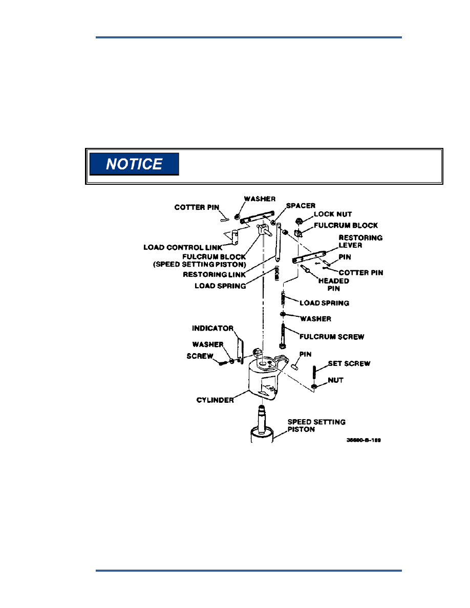
32.  Assemble speed-setting servo (Figure 5-55). 
 

a.  Insert piston through cylinder and fulcrum block. 


b.  Place both fulcrums in position between restoring-lever straps. 


c.  Place restoring link and spacers between restoring levers and secure 

assembly together with pin and cotter pins. 


d.  Install fulcrum screw, washer, spring, and secure with nut. 


e.  Attach square end of fulcrum screw with pin. 


f. 

Install setscrew and nut. 


g.  Attach load-control link with headed pin and secure with cotter pin. 


When doing the following step, be careful not to buckle triangular 
plate. Also, be careful not to warp flat springs on triangular plate 
while you tighten screws. 


Figure 5-55. Speed Setting Servo 


33.  Set speed-setting cylinder assembly in place and fit triangular plate under 

top of retaining screw. Secure both to column with screws and washers. 
Torque screws to 50 lb-in (5.6 Nm) (Figure 5-56). 

 
34.  Fit "D" solenoid cup (opening toward speed-setting servo) and regulating-

bushing retainer in position on top of thrust bearing and secure with washer, 
collar, spring and hex head screw. 


PGEV and PGE Locomotive Governors 

Manual 36703 


78 

Woodward 


Figure 5-56. Speed Setting and Triangular Plate 


35.  Install washer and retainer screw, set pointer to punch mark in column 

surface, and tighten retainer screw. 

 
36.  Limiter assembly (Figures 5-57, 5-58, 5-59). 
 

a.  Clean orifice screen. 


b.  Replace old check valve, O-rings, and gaskets with new ones. 


c.  Orifice plates must have holes 180 degrees out of phase when 

assembled in case. 


d.  After assembly in case, install in limiter housing. 


e.  Lubricate and put new O-ring on bellows. 


f. 

Check bleed valve in valve-seat contact areas for nicks or burrs. If 
either of these critical areas are damaged, replace it with a new part. 


g.  Put valve seat in housing (with seat up) and install snap ring. 


h.  Install spacer and bellows, and secure with new Nylok screws. 


i. 

Use new copper washers and install eccentric in housing. 


j. 

Insert bleed valve, spring seat, restoring-spring seat, sensor piston, 
and sleeve (Figure 5-58). 


k.  Insert loading spring, pilot-valve plunger, and amplifier piston. 


l. 

Assemble bearing in bellcrank and secure bellcrank to linkage bracket 
with pin and cotter pin. 


m.  Turn in adjusting screw. Place feedback lever in position and secure 

floating lever to bellcrank with cotter pin. 


n.  Place fuel-limit lever in place on the bracket and secure with pin and 

cotter pin. 


o.  Attach fuel-limit lever to bracket and secure with cotter pin. 


p.  Attach linkage assembly to housing with 3 screws. 


q.  If it is present, assemble overriding solenoid (ORS) bracket and attach 

it to overriding solenoid (Figure 5-61). 


See Figure 5-59 which shows linkage arrangement of fuel limiter. 


Manual 36703 

PGEV and PGE Locomotive Governors 


Woodward 

79 


Figure 5-57. Fuel Limiter Orifice 


PGEV and PGE Locomotive Governors 

Manual 36703 


80 

Woodward 


Figure 5-58. Fuel Limiter Sensor and Bellows 


Figure 5-59. Linkage Arrangement 


Content   ..  20  21  22  23   ..