PGEV and PGE Locomotive Governors. Manual - part 20
 

  Index      Locomotives - books     PGEV and PGE Locomotive Governors - manual 1990


Search            


Content   ..  18  19  20  21   ..


PGEV and PGE Locomotive Governors. Manual - part 20


Manual 36703 

PGEV and PGE Locomotive Governors 


Woodward 

69 


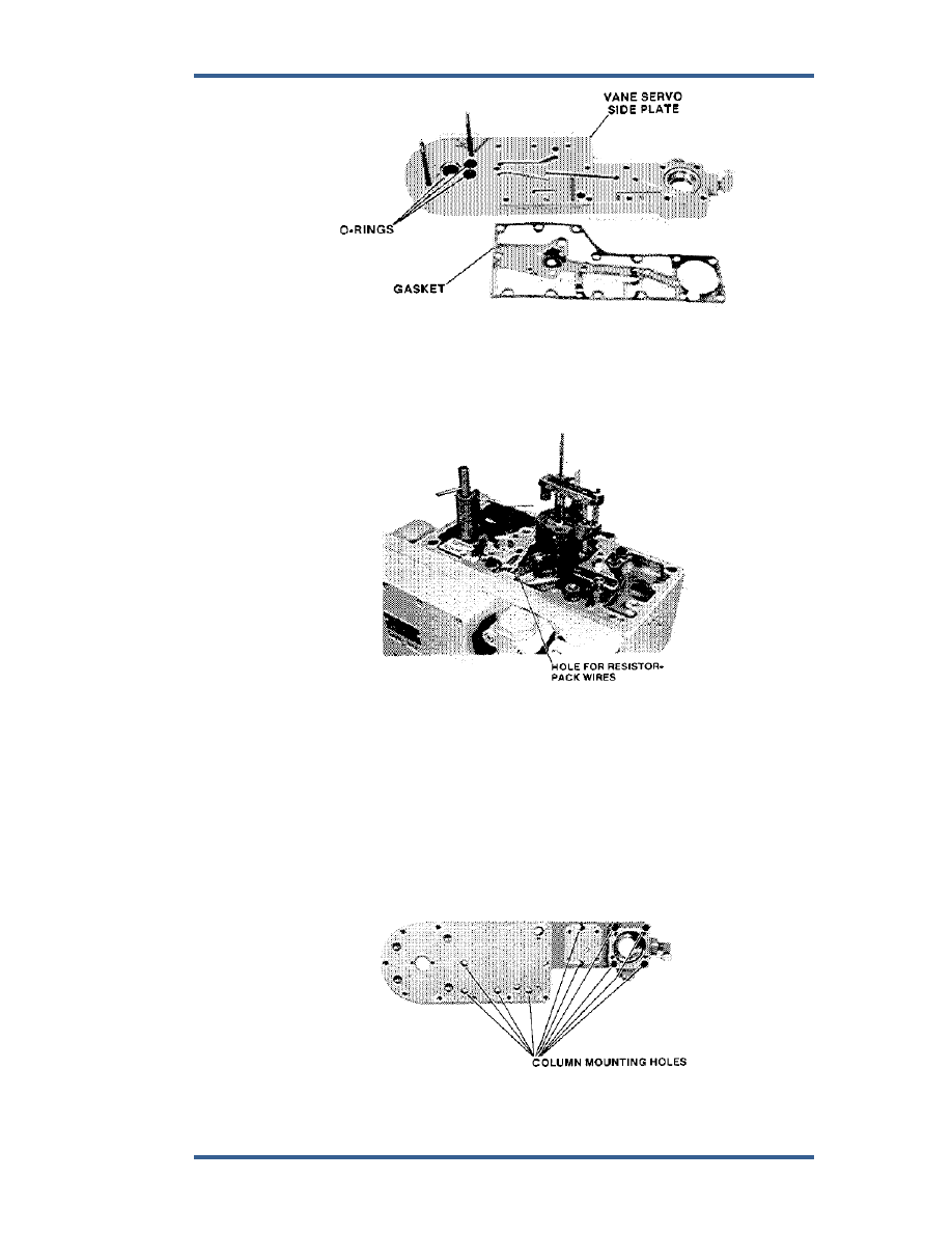
Figure 5-42. Side Plate 


14.  Secure commutator plate, and wire retainer to resistor pack with screws and 

nuts (Figure 5-43). 


Figure 5-43. Wires Threaded into Column 


15.  Place gasket in position on side of column. 
 
16.  Attach side plate to column with 10 screws. Torque screws to 75 lb-in (8.5 

Nm). To insure plate flatness, when torquing screws, start from the center 
and work your way to the ends. 

 
17.  Thread resistor-pack wires through gasket, side plate, gasket, and hole in 

column (Figures 5-44, 5-45). 


Figure 5-44. Side Plate Mounting Holes 


PGEV and PGE Locomotive Governors 

Manual 36703 


70 

Woodward 


Figure 5-45. Resistor Pack and Side Plate Assembly 


18.  Attach resistor pack to side plate. First, use 2 screws through commutator, 

but do not tighten. Second, in order as shown on Figure 5-45, secure right-
hand side of resistor pack to column. Tighten screws on left-hand side in 
commutator. 

 
19.  Insert end of shaft in contact plate assembly (Figure 5-46), through 

commutator and side plate, and secure with retaining ring. Lift up gently on 
contact so it slides over commutator. 


Manual 36703 

PGEV and PGE Locomotive Governors 


Woodward 

71 


Do not bend contact on plate as you slide the plate in position. 


Figure 5-46. Contact Plate Assembly 


20.  Make sure the vane has maximum amount of travel. If necessary, pull 

contact plate out slightly and rotate positioning of teeth to obtain maximum 
travel. 

 
21.  Secure contact-plate shaft with snap ring. 
 
22.  Attach vane assembly to side plate with lockwashers and nuts. 
 
23.  Attach side-plate cover to side plate. Holes in top right (Figure 5-47) need 

four 3 inch (76 mm) long screws. Eight other holes require 2-1/8 inch (54 
mm) screws. 


Figure 5-47. Side Plate Cover 

PGEV and PGE Locomotive Governors 

Manual 36703 


72 

Woodward 

24.  Assemble oil filter after cleaning it and mount it in position on vane servo 

side plate (Figure 5-48). 


Figure 5-48. Oil Filter 


25.  Install load spring, spring seat, O-ring, and end cap. Secure with 

lockwashers and screws (Figure 5-49). 


During test on test stand, adjust shutdown point and then install plug 
in end cap. Use Loctite 242 on outside diameter of plug. 


Content   ..  18  19  20  21   ..