PGEV and PGE Locomotive Governors. Manual - part 18
 

  Index      Locomotives - books     PGEV and PGE Locomotive Governors - manual 1990


Search            


Content   ..  16  17  18  19   ..


PGEV and PGE Locomotive Governors. Manual - part 18


Manual 36703 

PGEV and PGE Locomotive Governors 


Woodward 

61 


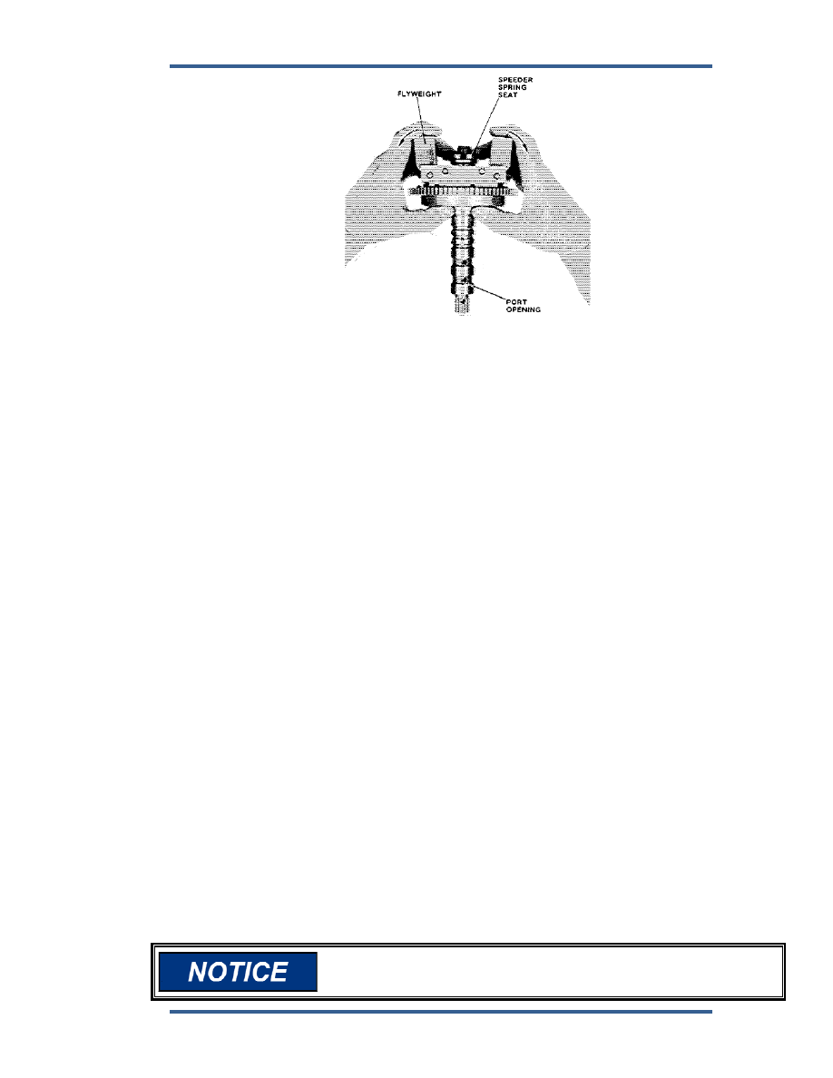
Figure 5-31. PVP Adjustment Procedure 


17.  Place thrust bearing on shutdown rod with race having largest hole on 

bottom. 


18.  Fit speeder spring in spring seat and place it on shutdown rod. 


19.  Place plug on top of speeder spring. This completes the ballhead assembly. 


Power Servo 


1.  Check piston and lightly remove any nicks or burrs with a small stone. 

Check shaft for wear and lightly polish with emery cloth if necessary. 


2.  Check cylinder for wear and remove nicks with emery cloth as required. 
 
3.  Insert piston in cylinder. 


4.  Press on oil seals just below flush, and press rod end on piston shaft. 

Secure with taper pin. For screw on type, screw on to 25 lb-ft (34 Nm). 
Then drill and pin with roll pin. 


5.  Put nut on tailrod and thread tailrod lift nut onto tailrod and fit the slotted end 

on piston shaft. Thread tailrod in until there is just enough clearance so 
tailrod lift nut can turn on piston. Tighten nut on tailrod lift nut to secure it in 
position. 


6.  Place gasket on cylinder and spring in cylinder. 


7.  Use jack screws or some type of guarded press to compress the spring 

guard on to cylinder and secure it with screws and washers. 


8. Install 

scale. 


9.  Install spring, seal, and O-ring 


10.  Check needle-valve seat for wear and install needle valve and washer. 

Screw in needle valve until it just bottoms. Then and back it off 2 turns. 


Do not overtighten the needle valve as this damages the seat. 


PGEV and PGE Locomotive Governors 

Manual 36703 


62 

Woodward 


Figure 5-32. Assembly of Power Servos 

Manual 36703 

PGEV and PGE Locomotive Governors 


Woodward 

63 

Power Case And Base 

(Figures 5-33 and 5-34) 


Figure 5-33. Power Case 

 
1.  Check for wear in gear pockets. Shiny spots indicate a side load on 

driveshaft. 

 
2.  Check surface (base and column) for burrs, and stone if required. 
 
3.  Install both accumulator pistons and secure with snap rings. 
 
4.  Use an arbor press and install accumulator springs and seats, and secure 

with snap rings. 

 
5.  Install all pipe plugs, oil drain and oil gauge. Use Loctite on all threads. 
 
6.  Install idler gear and check for free movement. 
 
7.  Install pump gear and check for free movement. 
 
8.  Lubricate and install preformed packing on base end of power case. 
 
9.  Place base in position on power case and with 4 screws in center holes on 

each side of base, secure base to poser case. Tighten screws evenly a little 
at a time. Check alignment by placing driveshaft in position and turn it to 
check oil pump for free movement. If pump does not move freely, loosen 
screws in base and reposition slightly until driveshaft turns freely. 

 
10.  Insert the other 4 screws in base and tighten. Torque to 90 lb-in (10.1 Nm) 

nominal. 

 
11.  Check driveshaft for wear in area where seal fits. 
 
12.  Replace bearing on driveshaft with a new bearing unless none is available 

and the old bearing is not damaged too badly. See Figure 5-34. 


PGEV and PGE Locomotive Governors 

Manual 36703 


64 

Woodward 


Figure 5-34. Drive Shaft and Base 


13.  Install gasket on seal and place into base. 
 
14.  Install driveshaft and secure with retainer plate and screws. Torque screws 

to 63 lb-in (7.1 Nm) nominal. 

 
15.  Bend ears of retainer plate to secure screws. 
 
16.  Put new 0-ring on plug (Figure 5-35) and insert spring and plug into 

compensation cylinder in power case. Secure plug with snap ring. 


Figure 5-35. Compensation System 


17.  Lay power case on its side and insert piston spring and spring seat in 

compensation cylinder on servo side of power case. Be sure both springs fit 
into ends of buffer piston. 

 
18.  Install gasket and power servo. 


When governor is on test stand and is at operating temperature, 
torque screws to 40 lb-ft (54 N

m). 


Content   ..  16  17  18  19   ..