PGEV and PGE Locomotive Governors. Manual - part 16
 

  Index      Locomotives - books     PGEV and PGE Locomotive Governors - manual 1990


Search            


Content   ..  14  15  16  17   ..


PGEV and PGE Locomotive Governors. Manual - part 16


Manual 36703 

PGEV and PGE Locomotive Governors 


Woodward 

53 

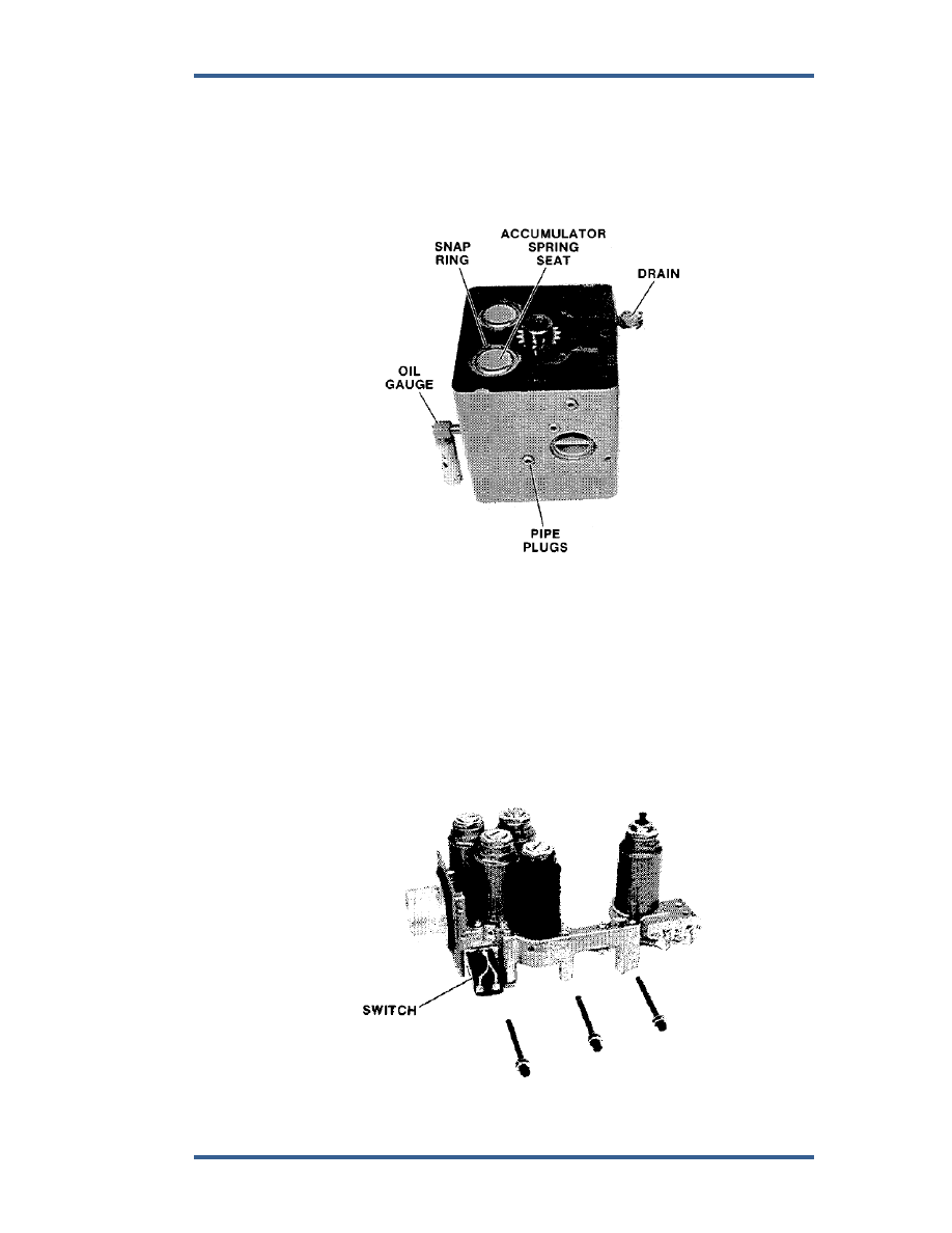
28. Power Case Disassembly 
 

a.  Use an arbor press to hold the spring and remove the snap ring. Slowly 

release the compressed accumulator spring and spring seat (Figure  
5-22). 


b.  Remove oil gauge. 


c.  Remove all plugs. 

 d. 

Remove 

drain. 


Figure 5-22. Power Case 


29.  Solenoid Pack Disassembly (Figures 5-23 and 5-24). 
 

a.  Disconnect wires and remove switch from receiver assembly. 


b.  Remove nut from solenoid. 


c.  Screw plunger stop out of case. 


d.  Screw case out of receiver assembly. 


e.  Remove load spring, insulator, and plunger. 


f. 

Remove soldered wires from solenoid coil. 


g.  Remove guide, bushings, and shield washers. 

 h. 

Disassemble 

all 

solenoids. 


Figure 5-23. Solenoid Pack and Receiver 


PGEV and PGE Locomotive Governors 

Manual 36703 


54 

Woodward 


Figure 5-24. Solenoid and Receiver Assembly 


30.  Speed-Setting Cylinder Disassembly (Figure 5-25). 
 

a.  Remove nut and pin from fulcrum screw. 


b.  Remove headed pin and separate restoring lever into 2 pieces. 


c.  Press piston rod out of fulcrum block, being careful not to drop piston. 

 d. 

Remove 

stop 

screw. 


Figure 5-25. Speed Setting Cylinder 


31. Fuel-Limiter Disassembly. 
 

a.  Remove snap ring and lift out pivot and adjusting screw (Figure 5-26). 


b.  Take out loading spring. 


c.  Remove cotter pin, fuel-limit-lever pivot pin and fuel-limit lever. 


d.  Remove feedback lever. 


e.  Remove screws (2 on top and 1 from bottom) and lift off bracket. 


f. 

Remove cotter pins from top of bellcrank and remove bellcrank. 


g.  Remove pin from bellcrank. 


h.  Remove cotter pin, pin, and bearing from bellcrank. 


i. 

Lift out amplifier piston, pilot-valve plunger and load spring. 


j. 

Lift out sensor piston sleeve, piston and fuel limit cam assembly. 


Manual 36703 

PGEV and PGE Locomotive Governors 


Woodward 

55 


Do not separate cam from piston unless cam is damaged or worn. 


k.  Lift out spring and seats, and bleed valve. 


l. 

Remove 2 Nylok screws and take out bellows, spacer, and valve seat. 

 m. 

Remove 

eccentric. 


n.  Remove O-ring, screen, O-ring, and check-valve. 


o.  Remove snap ring, washers, gaskets, orifice plates, and spring from 

the orifice body. 


Figure 5-26. Fuel Limit Bracket and Linkage 

PGEV and PGE Locomotive Governors 

Manual 36703 


56 

Woodward 

32.  Power servo disassembly (Figure 7-5 or 7-6). 


The linear output power servo is spring loaded. Use some type of 
press or jack screws when disassembling the servo. 


See Figure 7-5 for Linear Output Servo. 


a.  Remove spring, seal ring, and seal. 


b.  Use jack screws and some type of press to hold spring guard while 

loosening screws. 


c.  Remove pin and separate rod end from piston. 

 d. 

Remove 

seals. 


See Figure 7-6 for Rotary Output Servo Disassembly. 

 
33.  Water Box disassembly. 
 

See Figure 5-69. 


Figure 5-27. Fuel Limiter Sensor and Bellows 


Content   ..  14  15  16  17   ..