PGEV and PGE Locomotive Governors. Manual - part 15
 

  Index      Locomotives - books     PGEV and PGE Locomotive Governors - manual 1990


Search            


Content   ..  13  14  15  16   ..


PGEV and PGE Locomotive Governors. Manual - part 15


Manual 36703 

PGEV and PGE Locomotive Governors 


Woodward 

49 


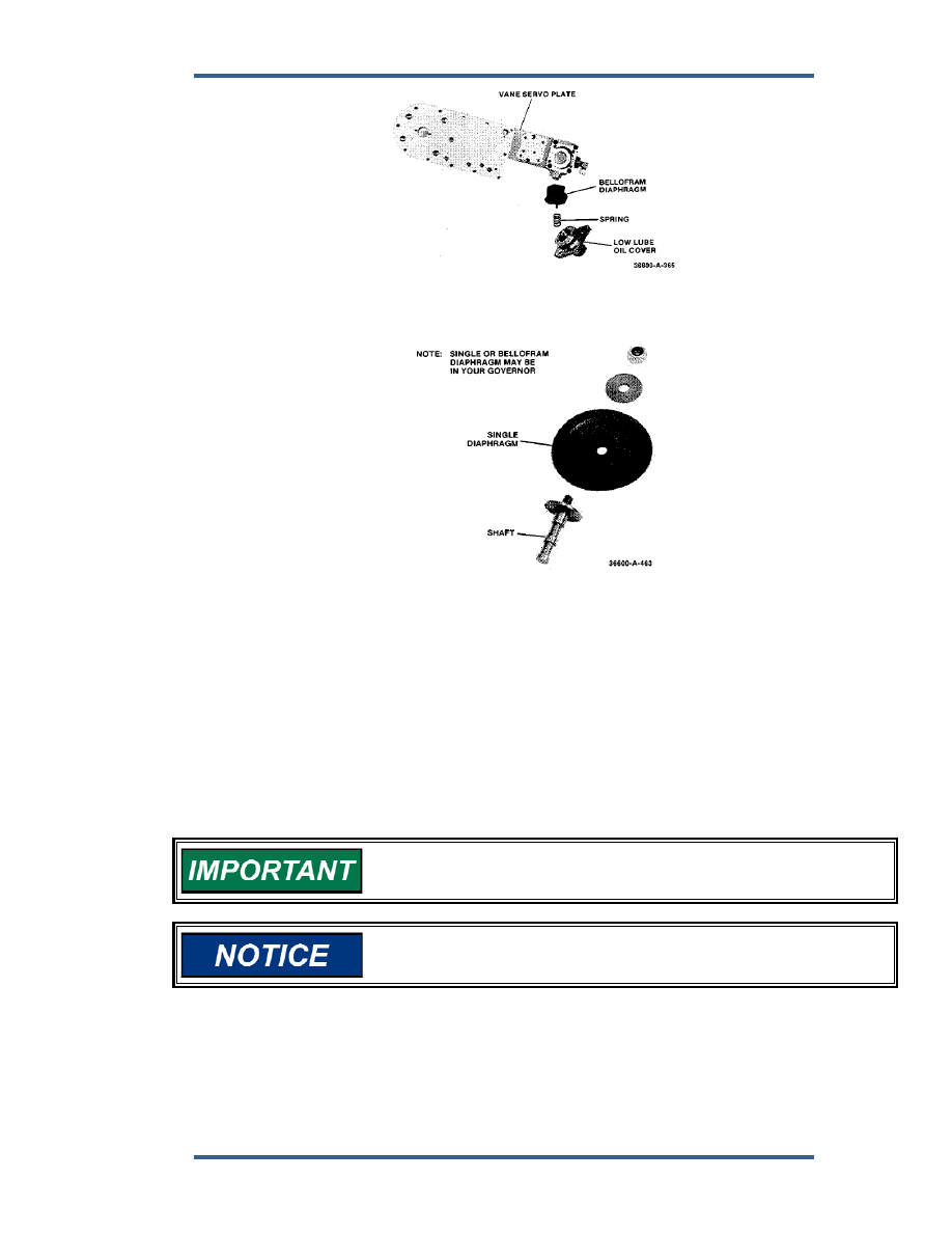
Figure 5-14. Low Lube Oil Cover and Diaphragm 


11.  Remove snap ring and lift out contact plate and indicator assembly (Figure  

5-12). 

 
12.  Remove 2 screws under contact plate and 2 screws and spacers from end 

of resistor pack and remove resistor pack (Figure 5-12). 

 
13.  Remove 4 screws and oil filter (Figure 5-13). 
 
14.  remove low-lube-oil cover, spring, gasket, and diaphragm (Figures 5-13 and 

5-14). 


If cover will not come off, remove adjustment screw from center of 
cover. 


Be careful to not damage bellofram (diaphragm) when removing it. 

 
15.  Remove side plate and gasket, along with pressure-reducing valve sleeve, 

plunger, and spring from the column (Figure 5-15). 


PGEV and PGE Locomotive Governors 

Manual 36703 


50 

Woodward 


Figure 5-15. Side Plate 


16.  Remove low-lube-oil valve bushing, piston, spring, and gasket (Figure 5-16). 


Figure 5-16. Low Lube Oil and Timing Valve Systems 


17.  Remove screw and plates and lift out two timing valves. 
 
18.  Remove 4 screws. If water box is present, disconnect both tubes from 

column. Then separate column from power case (Figure 5-16). 

 
19.  Lift ballhead assembly out of power case (Figure 5-17). 


Figure 5-17. Power Case and Power Servo 

Manual 36703 

PGEV and PGE Locomotive Governors 


Woodward 

51 

20.  Remove spring, spring seat, and seal (Figure 5-17). 
 
21.  Remove 4 screws. Remove 2 screws and water box from power case. Then 

separate power servo from power case. 

 
22.  Remove spring seat and spring from power servo side of the power case 

(Figure 5-18). 


Figure 5-18. Compensation System 


23.  Remove snap ring, plug, O-ring, spring, and buffer piston (Figure 5-18). 
 
24.  Turn power case upside down, remove 8 screws and lift off base (Figure  

5-17). 


If base does not separate easily from power case, use a screw driver 
in slots to pry apart. 

 
25.  Remove 3 screws and retainer plate. Lift out drive shaft seal and gasket 

(Figure 5-19). 


Figure 5-19. Drive Shaft 

PGEV and PGE Locomotive Governors 

Manual 36703 


52 

Woodward 

26.  Remove drive gear and idler gear from power case (Figure 5-20). 


Figure 5-20. Power Case and Base 


27.  Ballhead disassembly (Figure 5-21). 
 

a.  Turn speeder spring, and remove spring and check plug from spring 

seat. 


b.  Loosen PVP (pilot-valve plunger) nut and remove the shutdown rod. 


c.  Lift off spring seat, thrust bearing, washer, and adjusting spring. 


d.  Remove 4 pins and flyweights. 


e.  Remove screw and spring coupling. 


f. 

Remove 8 screws and flyweight head. 


g.  Take out O-ring and bearing. 


h.  Remove snap ring, bushing, and pilot-valve plunger. 


You can be injured by accumulator springs because they are under 
compression. Use an arbor press and be careful when removing 
them. 


Figure 5-21. Ballhead Assembly 


Content   ..  13  14  15  16   ..