PGEV and PGE Locomotive Governors. Manual - part 14
 

  Index      Locomotives - books     PGEV and PGE Locomotive Governors - manual 1990


Search            


Content   ..  12  13  14  15   ..


PGEV and PGE Locomotive Governors. Manual - part 14


Manual 36703 

PGEV and PGE Locomotive Governors 


Woodward 

45 


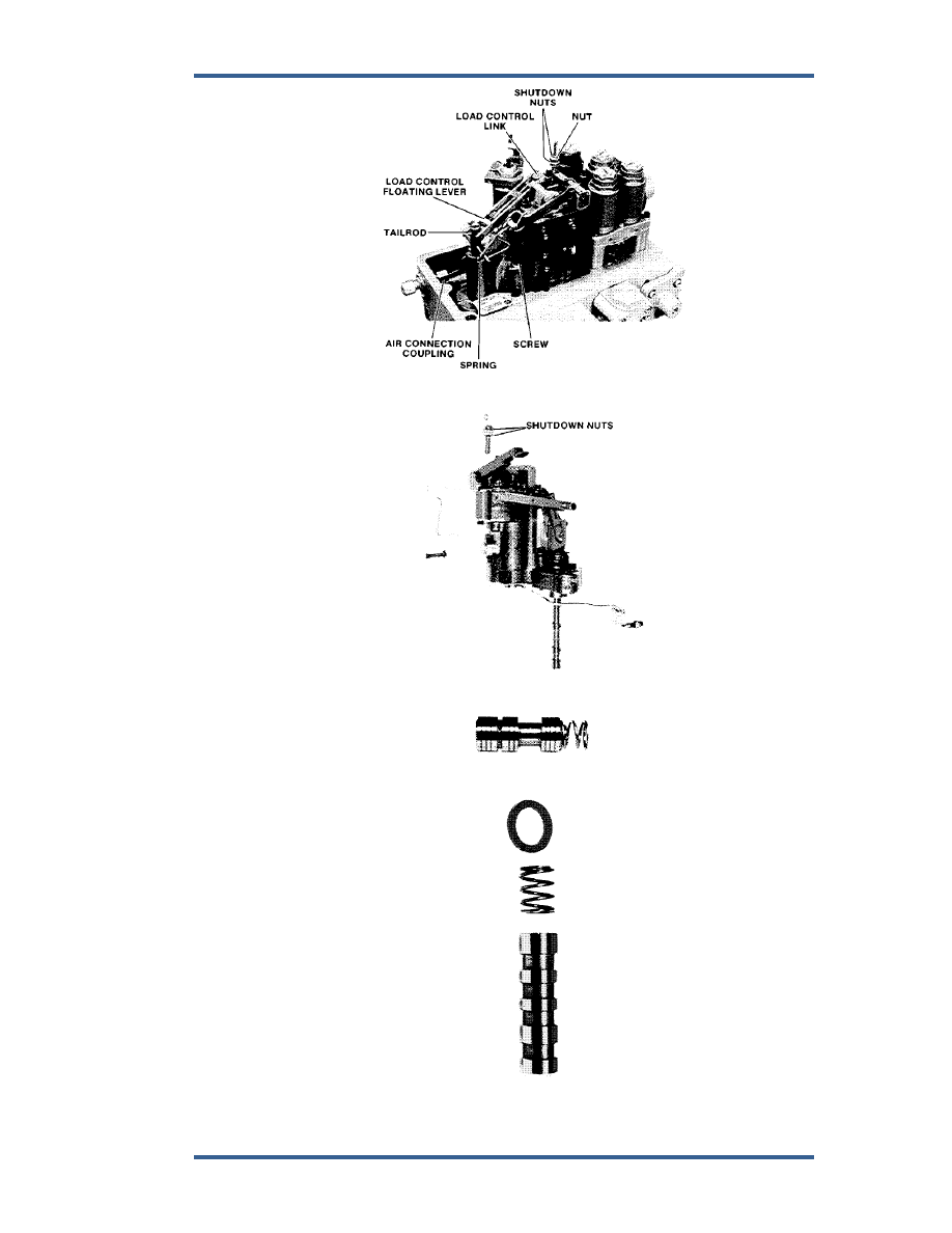
Figure 5-3. Fuel Limiter Installed 


Figure 5-4. Fuel Limiter Assembly 


Figure 5-5. Overriding Solenoid Spring and Piston 


Figure 5-6. Load Control Bushing, Spring, and Gasket 

PGEV and PGE Locomotive Governors 

Manual 36703 


46 

Woodward 

5.  Remove triangular plate and speed-setting cylinder (Figure 5-7). 
 a. 

Remove 

screws. 


b.  Remove pin that connects restoring link to restoring lever. 


c.  Lift off speed-setting cylinder and spring (Figure 5-8). 


Figure 5-7. Triangular Plate and Speed Setting Cylinder Installed on Column 


Figure 5-8. Speed Setting Cylinder and Triangular Plate 


6.  Remove 2 screws and lift off time delay mechanism (Figures 5-9 and 5-10). 


Manual 36703 

PGEV and PGE Locomotive Governors 


Woodward 

47 


Figure 5-9. Time Delay Mechanism Installed 


Figure 5-10. Time Delay Mechanism and Speed Setting Pilot Valve Assembly 


7.  Lift out speed setting plunger, bushing, floating lever, and load spring 

(Figure 5-10). 

 
8.  Remove the bypass valve (Figure 5-9 and 5-11). 


Figure 5-11. Bypass Valve 

PGEV and PGE Locomotive Governors 

Manual 36703 


48 

Woodward 

9.  Remove side plate cover, 12 screws (Figure 5-12). 


Figure 5-12. Vane Servo 


10.  Remove vane servo (Figures 5-13 and 5-14). 


Figure 5-13. Vane Servo and Oil Filter 


Content   ..  12  13  14  15   ..