PGEV and PGE Locomotive Governors. Manual - part 17
 

  Index      Locomotives - books     PGEV and PGE Locomotive Governors - manual 1990


Search            


Content   ..  15  16  17  18   ..


PGEV and PGE Locomotive Governors. Manual - part 17


Manual 36703 

PGEV and PGE Locomotive Governors 


Woodward 

57 


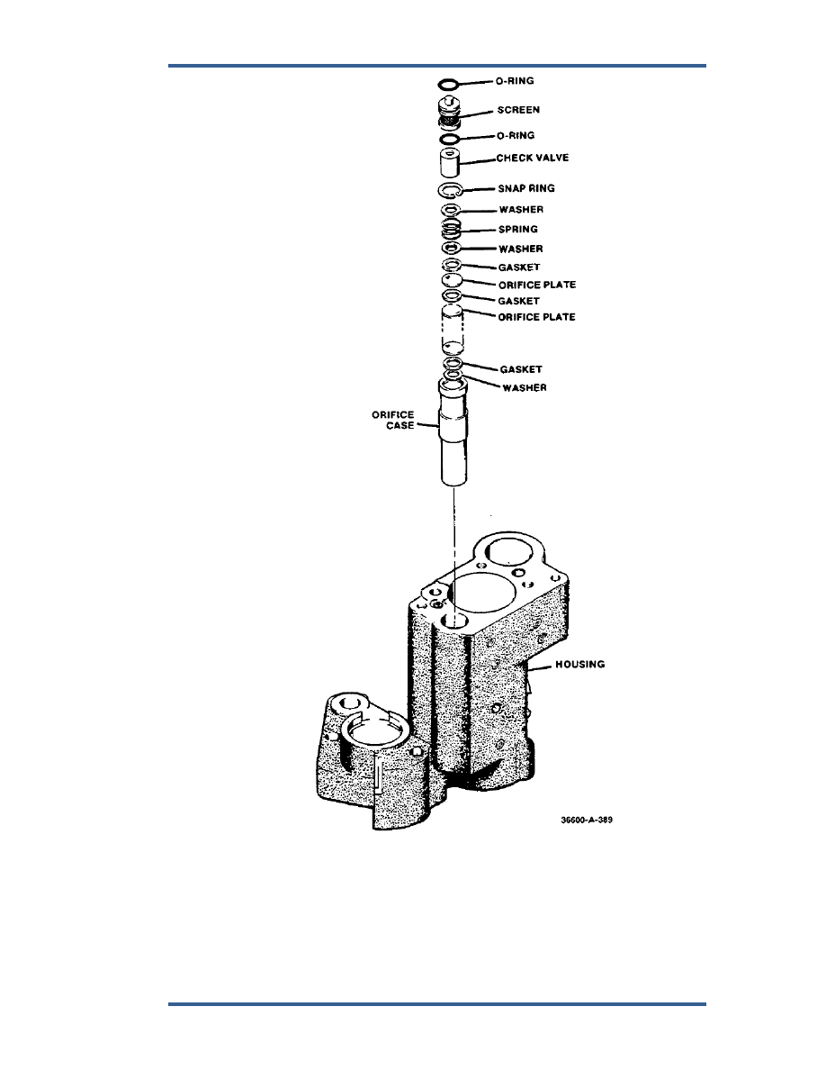
Figure 5-28. Fuel Limiter Orifice 


PGEV and PGE Locomotive Governors 

Manual 36703 


58 

Woodward 


Figure 5-29. Speed Setting Servo 

(Optional start fuel limiter parts are shaded.) 

Manual 36703 

PGEV and PGE Locomotive Governors 


Woodward 

59 

Repair or Replacement 

 
Repair of parts should be limited to removal of minor nicks, burrs or corrosion. 
Polish slightly corroded areas in mating surfaces using a fine (600 grit) abrasive 
cloth or paper and oil. Repair or rework to any greater extent is impractical and 
the part should be replaced. 


Handle critical parts with extreme care so that mating edges and 
surfaces will not be damaged. Sharp edges of plunger lands, piston 
grooves, metering ports, etc., must be maintained. Rounded edges, 
nicks, or other damage to such edges will result in excessive internal 
leakage and/or decreased control sensitivity. 


Cleaning 

 
1.  Clean critical parts by hand. 
 a. 

Pilot-valve 

plungers. 

 b. 

Pilot-valve 

bushings. 

 c. 

Compensation 

piston. 

 d. 

Servo 

piston. 


e.  Low-oil shutdown piston. 

 f. 

Needle 

valves. 

 g. 

Bypass 

valve. 

 h. 

Load-Control 

bushing. 

 i. ORS 

piston. 

 
2.  Clean resistor pack by submerging it in clean solvent and shaking it around. 

Blow dry with a jet of dry air. 

 
3.  Pressure wash castings and other parts. 


Lubrication 

 
Lubricate metal parts liberally with lubricating oil at time of assembly. Lubricate 
O-rings with petrolatum before installation. Also, lubricate any press-fit parts, 
bearings, and seals before installing. 
 

Assembly 

 
Assembly should be performed in a dust-free work area. 
 
Replace any damaged or worn parts with new parts. 
 
Replace O-rings, cotter pins, belloframs, and gaskets with new parts. Obtain new 
O-rings, gaskets, sealing washers, retaining rings, cotter pins, etc., to replace 
those removed during disassembly. Install retaining rings with sharp edge in the 
direction of the applied force. 
 
Use "Ersin Multicore Activated Resin Core Solder" or equivalent when making 
electrical connections to solenoid coil (1106, Figure 7-16) or connectors (1126 or 
1134). Use solder sparingly to avoid flow of excess solder through shield 
washers (1135) which may short circuit the terminals to ground. 

PGEV and PGE Locomotive Governors 

Manual 36703 


60 

Woodward 

Ballhead 

 
1.  Check the toe wear on the flyweights. Flyweight toes support the thrust 

bearing. Replace flyweights if there is a flat spot larger than 1/32 inch (0.8 
mm) wide. 

 
2.  Check flyweight pins. Wear on pins indicate bad bearings in the flyweights. 

Replace both pins and bearings. 

 
3.  Check the thrust bearing by placing the bearing between the races and 

rotating it in your hand. If the bearing feels rough, replace it. 

 
4.  Check the main bearing by inserting two fingers inside the inner race and 

apply pressure while spinning the outer race with your other hand. 

 
5.  Check the pilot-valve plunger for nicks and wear. Replace the PVP if it has 

any nick in the control land larger than 0.001 inch (0.03 mm). 

 
6.  Use a light and check inside the PVP bushing. Be sure there are no nicks on 

the control port. 

 
7.  Check the spring coupling by twisting slightly. The spring should not be 

loose. (See Figure 7-2). 

 
8.  Insert PVP and bushing in gear-bushing assembly and secure with snap 

ring. 

 
9.  Install spring coupling in flyweight head. The spring coupling has a missing 

tooth in its gear and fits in one position only. 

 
10.  Put bearing in gear-bushing assembly. 
 
11.  Lubricate O-ring and place it on gear bushing. 
 
12.  Place small spring and shutdown rod on PVP and secure with PVP nut. 
 
13.  Fasten flyweight head to gear-bushing assembly with eight screws. 
 
14.  Install flyweights in flyweight head. 
 
15.  Place adjusting spring and washer on shutdown rod. 
 
16.  Adjust PVP nut until PVP control land is centered in the control port of the 

PVP bushing. See Figure 5-30 and adjust the PVP nut until dimensions 'A' 
and 'B' are equal. Make the adjustment (Figure 5-31) while keeping a slight 
pressure on the flyweights in both directions. Pin nut (with cotter pin) in 
position once adjustment is correct. 


Figure 5-30. PVP Adjustment 


Content   ..  15  16  17  18   ..