PGEV and PGE Locomotive Governors. Manual - part 19
 

  Index      Locomotives - books     PGEV and PGE Locomotive Governors - manual 1990


Search            


Content   ..  17  18  19  20   ..


PGEV and PGE Locomotive Governors. Manual - part 19


Manual 36703 

PGEV and PGE Locomotive Governors 


Woodward 

65 

19.  Reassemble water box and attach it to power case. 
 
20.  Put small gasket in top of power case (Figure 5-36. 


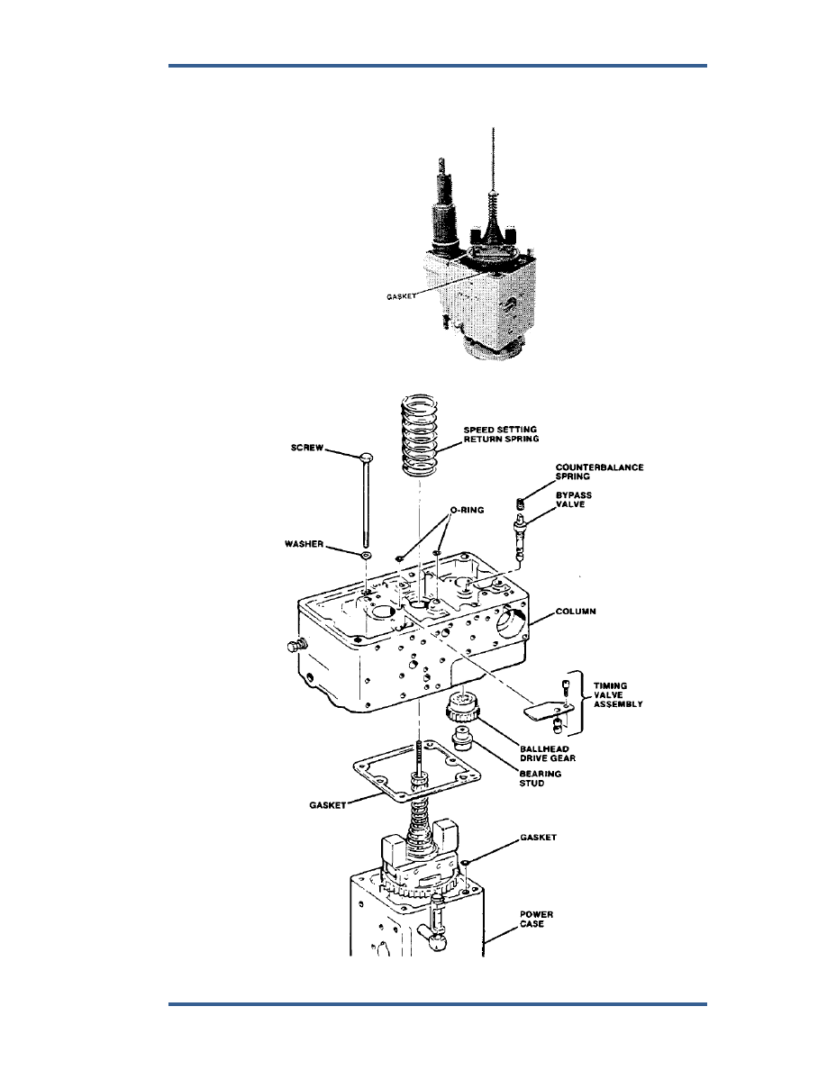
Figure 5-36. Power Case Assembly Complete 


Figure 5-37. Column to Power Case Assembly 

PGEV and PGE Locomotive Governors 

Manual 36703 


66 

Woodward 

21.  Insert ballhead assembly in position in power case. 


Column 

(Figures 5-38 through 5-66) 
 
1.  Check ballhead drive-gear teeth. If gear is okay, place in position in bottom 

of column. 

 
2.  Clean both timing valves, replace O-rings on needle valves, insert in 

column, and secure with retainer plate, instruction plate, lockwasher and 
screw (Figure 5-38). 


Figure 5-38. Timing Valve 


3.  Install bulkhead union assembly as shown in Figure 5-39. 


Figure 5-39. Lube Oil Shutdown 

Manual 36703 

PGEV and PGE Locomotive Governors 


Woodward 

67 

4.  Insert gasket, plunger, spring, piston, and bushing into hole for low-oil 

shutdown (Figure 5-39). 

 
5.  Assemble diaphragms as shown in Figure 5-39 or 5-39A. 


Do not let the diaphragm twist or buckle while tightening the nut. 


Figure 5-39A. Differential Area Lube Oil Shutdown 


Figure 5-40. Load Control Supply Valve 


6.  Tighten nut on plunger to secure assembly. 

PGEV and PGE Locomotive Governors 

Manual 36703 


68 

Woodward 

7.  For differential-area lube-oil shutdown, roll diaphragm into area around 

piston inside of spacer. Do not use a sharp tool to start the diaphragm; 
usually it can be started with your finger. 

 
8.  Insert diaphragm assembly into cylinder for lube-oil system. 
 
9.  Install load-control supply valve in order as shown and in correct hole in 

column. 

 
10.  Replace bearings, if required, in end plate. See Figure 5-41. Use a brass 

punch through bearing end to remove end cap. Then reverse end plate and 
drive out bearing. Press fit new bearings into both end plates. 


Figure 5-41. Vane Assembly 


11.  Assemble servo shaft, vane inserts, and springs into housing. 


Use new springs with vane inserts. 

 
12.  Put oil seals in place on housing and secure end caps to housing with 

screws and lockwashers. 

 
13.  Install three O-rings, shown in side plate, Figure 5-42. 


Content   ..  17  18  19  20   ..