PGEV and PGE Locomotive Governors. Manual - part 21
 

  Index      Locomotives - books     PGEV and PGE Locomotive Governors - manual 1990


Search            


Content   ..  19  20  21  22   ..


PGEV and PGE Locomotive Governors. Manual - part 21


Manual 36703 

PGEV and PGE Locomotive Governors 


Woodward 

73 


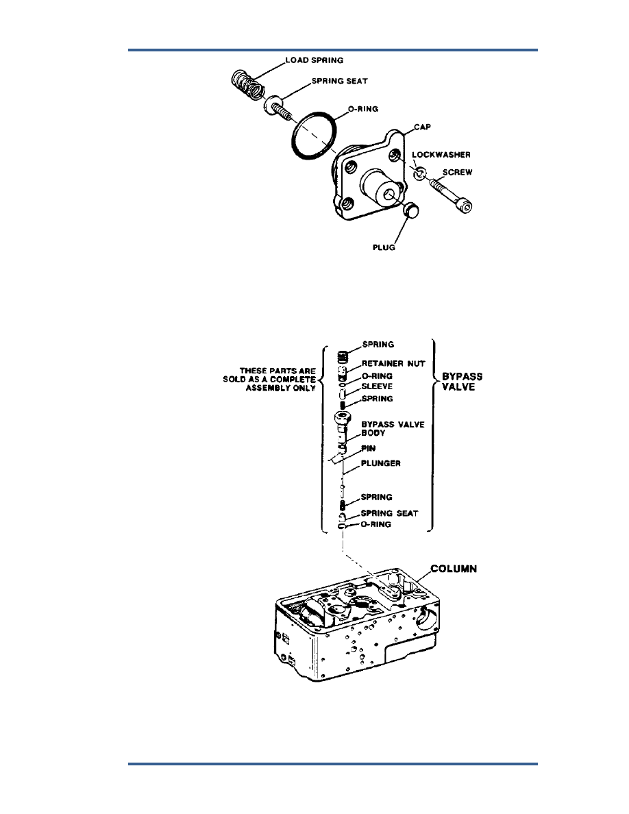
Figure 5-49. Lube Oil Shutdown Cap 


26.  Clean, assemble, and install bypass valve in position as shown in Figure  

5-50. 


Figure 5-50. Bypass Valve 

PGEV and PGE Locomotive Governors 

Manual 36703 


74 

Woodward 

27.  Assemble load-control linkage as follows: 
 

a.  Install snap ring in load control bushing (Figure 5-51). 


Figure 5-51. Load Control Bushing 


b.  Put load control bushing into column bore; install load-control pilot-

valve plunger, spring, gasket, and spacer. 


c.  Press the cylinder head into cylinder, (Figure 5-52). 


d.  Place O-ring in counterbore in column; slip cylinder over pilot-valve 

stem and tighten down with screws and washers. 


e.  Install overriding piston. 


f. 

Hold pilot-valve plunger down against snap ring and use Woodward 
tool 360692 or equivalent (Figure 5-53.) to thread spring seat onto 
plunger stem. Turn spring seat down until it touches overriding piston; 
then back off 1/4 turn. (Plunger will begin to rise if spring is turned 
down further on thread after touching piston.) 


Manual 36703 

PGEV and PGE Locomotive Governors 


Woodward 

75 


Figure 5-52. Load Control Pilot Valve Assembly 


Figure 5-53. Spring Seat Tool 

PGEV and PGE Locomotive Governors 

Manual 36703 


76 

Woodward 


g.  Lift pilot-valve plunger sufficiently far to permit holding spring collar with 

a wrench while locking in position with locknut. 


Do not lift plunger higher than necessary, to avoid damaging oil seal. 


h.  Install spring, spring retainer, and retaining ring. 


i. 

Thread locknut onto pilot-valve plunger stem and install washer. 


j. 

Assemble block, eccentric, load-control link, fulcrum block, floating 
lever, range-adjustment screw, spring, and knob. 


k.  Thread adjusting block of the floating-lever assembly about 10 turns 

onto the pilot-valve plunger, lock in place with locknut. 


28.  Check thrust bearing for wear and replace if necessary. 


29.  Check pilot-valve plunger and rotating bushing for damage or wear and 

repair or, replace it necessary. Be sure there are no nicks or burrs on any 
lands. Lightly stone any nicks or burrs with a hard Arkansas stone. 


30.  Insert loading spring, rotating bushing, regulating bushing, small pilot-valve 

loading spring, pilot-valve plunger, and thrust bearing (Figure 5-54. Install 
thrust bearing with large race on top. 


Figure 5-54. Speed Setting Valve 


Content   ..  19  20  21  22   ..