Haima S5. A/C, Restraint System, Body Accessories, Electrical System. Manual - part 9


  Index      Haima     Haima S5. A/C, Restraint System, Body Accessories, Electrical System. Manual


Search            copyright infringement  


Content      ..     7      8      9      10     ..


Haima S5. A/C, Restraint System, Body Accessories, Electrical System. Manual - part 9


Electrical System 3D-32


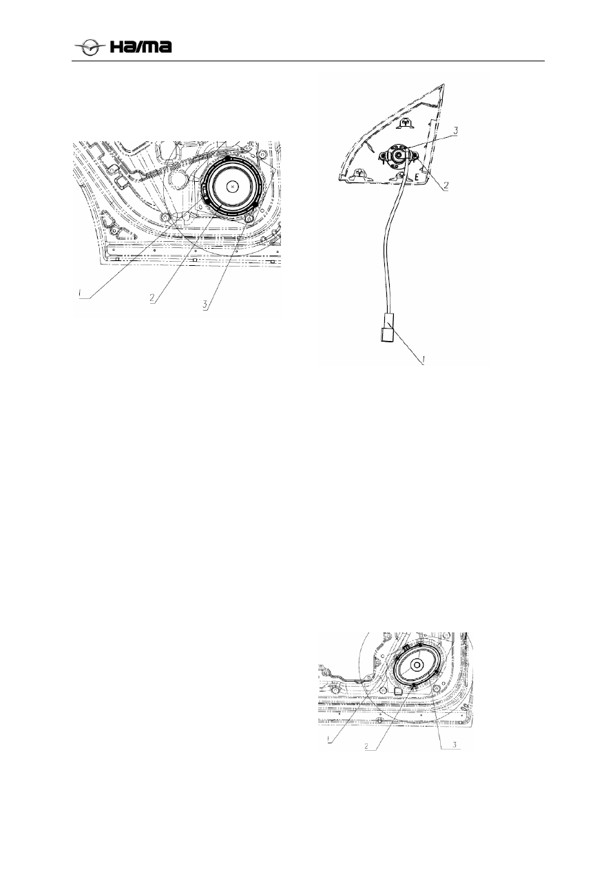
  Unscrew three  mounting screws from the 

speaker 3.  

  Remove the connector 1. 

  Remove the speaker 2 . 


Installation Procedure 

1.  Connect the speaker power plug 1. 

2.  Tighten the mounting screws 3. 

3.  Install the rear door trim plate by referring to 

the removal method of the door inner trim 
plate. 

4.  Connect the negative cable of the battery. 

Removal Procedure of Tweeter 

1.  Disconnect the negative cable of the battery.  

2.  Open the front door trim triangle.  

3.  Remove the tweeter from the front door trim 

triangle. 

  Remove the connector 1. 

  Unscrew the mounting screws from the 

tweeter 2.  

  Remove the tweeter 3 . 


Installation Procedure 

1.  Install the tweeter on the front door trim 

triangle with two mounting screws. 

2.  Connect the tweeter plug. 

3.  Connect the negative cable of the battery. 

Removal Procedure of Front Door 
Speaker 

1.  Disconnect the negative cable of the battery.  

2.  Remove the front door trim plate by referring 

to the removal method of the door inner trim 
plate.  

3.  Remove the speaker. 

  Unscrew four  mounting screws from the 

speaker 2.  

  Remove the connector 1. 

  Remove the speaker 3. 


Installation Procedure 

1.  Connect the speaker power plug . 

-------------------------------------------------------------------------------------------------------------------------------------------------------------


Electrical System 3D-33


2.  Tighten the mounting screws . 

3.  Connect the negative cable of the battery. 

Roof Antenna 

Removal Procedure 

1.  Disconnect the negative cable of the battery.  

2.  Remove the interior ceiling. 

3.  Remove the roof antenna. 

● Remove the antenna mounting bolts ①. 

● Remove the antenna ②. 


Installation Procedure 

1.  Tighten the mounting bolt of the antenna. 

2.  Tighten the mounting bolt of the antenna to 

the torque of 6N.m±0.5N.m. 

3.  Connect the negative cable of the battery. 


Immobilizer System 

Removal/Installation of Immobilizer 

 System 

Description 

 System 

Components 

The engine immobilizer system consists of the 
following three parts: the immobilizer controller, 
the key with embedded transponder and the 
immobilizer coil.  


PEPS forwarding configuration models are 
integrated in the Intelligent Key PCB board.


 Transponder 

Each key has a transponder, which is a passive 
electronic chip. During the system operation, it 
works together with the coil to complete the 
encryption and authentication between the 
transponder and the immobilizer controller. The 
effective information transmission distance of the 
transponder is 2cm-3cm. The transponder is a 
passive component, without being powered by the 
battery. The above figure shows the transponder in 
kind and its mounting position in the key.  

Notice:   

Because the transponder key is a precision 
component, please pay attention to the following 
points in use: 

1.  Don’t throw or tap the key, or do other 

actions to produce sudden impact on it. 

2.  Don’t keep the key in high temperature 

condition for a long time. 

3.  Don’t put the key into the washer for cleaning.  

4.  Don’t keep the key in the magnetic or 

electromagnetic environment 

 Immobilizer 

coil 

-------------------------------------------------------------------------------------------------------------------------------------------------------------


Electrical System 3D-34


The immobilizer coil, mounted on the ignition 
lock cylinder, is connected with the immobilizer 
controller via the harness, which undertaken the 
transmission of signals and energy between the 
immobilizer controller and the transponder.  


Immobilizer controller (IMMO) 

The immobilizer controller is a electronic 
control module consisting of the 
microprocessor and various semiconductor 
components and is the core component of the 
immobilizer system. 


Electrical Schematic Diagram 


Anti-theft system electrical schematics (without 
PEPS) 


Anti-theft system electrical schematics (with PEPS) 


System Operating Principle 

After the key with a transponder is inserted into the 
ignition lock and it is turned from OFF to ON, the 
immobilizer controller is awakened entering the 
wireless authentication status; at this time, the 
immobilizer controller outputs energy and data to 
the transponder via the coil. The transponder that 
installed in the key receives the wireless signal and 
transmits the encrypted ID signal back to the 
controller via the coil. The controller decodes the 
signal and compares the received ID with the 
internal stored ID. If they are the same, the 
wireless authentication is passed. If not, the 
controller ends the identification and enters the 
sleep mode.  

After passing the wireless identification, the 
immobilizer controller and the engine ECM will 

conduct the mutual encryption and authentication. 
They will compare the stored PIN with the key 
respectively. If they are the same, the ECM can 
start the engine successfully. If different, the ECM 
won’t start the engine.  

Some models, burglar match with PEPS function 
keys and PEPS mainly through intelligent control 
module, PEPS control module and anti-theft 
controller uses an internal algorithm using UMC 
between HITAG2 encryption and authentication 
algorithms, security controls and engine ECM is 
encrypted authentication, only the smart key and 
anti-theft controller (or PEPS and security 
controller), two anti-theft security authentication 
between the controller and the engine ECM 
through after all, it allows the engine to start the 
engine ECM normal. 


Immobilizer Indicator Lamp  

The immobilizer indicator lamp, which is 
controlled by the immobilizer controller, can 
display different status of the immobilizer system:  


1

After the vehicle is electrified and the key 
is located at ACC, the immobilizer 
controller is still under the standby mode; 
at this time, 5S cycle indicator flashes, each 
cycle indicator light 250ms;


2

With the key turned to ON, if the 
authentication between the immobilizer 
controller and the key fails, 0.5s cycle 
indicator flashing lights each cycle 250ms; 

3

With the key turned to ON, if the 
authentication succeeds, the indicator lamp 
goes out.


 Harness 

Connector 

The immobilizer controller is equipped with a 10-
pin connector, shown as follows:  


Schematic Diagram of the 10-Pin Connector of the 

Immobilizer Controller 

The 10-pin connector is connected with the female 

-------------------------------------------------------------------------------------------------------------------------------------------------------------


Electrical System 3D-35


terminal of the vehicle harness. The definition of 
pins are listed as follows:  

1


Terminal a of the coil


2


Positive power supply


3


Ignition switch


4


*


5


CAN-H


6


Terminal b of the coil


7


Ground


8


Low side driver


9


*


10


CAN-L


 Maintenance 

Instruction 

 Immobilizer 

Coil 

 (without PEPS) 


Removal Procedure: 

1.  Disconnect the negative cable of the battery.  

2.  Remove the steering column cover. 

3.  Remove the connector at the immobilizer coil 

end. 

4.  Remove the immobilizer coil from the ignition 

lock. 

Installation Procedure : 

1.   The installation of security coil; 

2.   Plug security coil insert; 

3.   Install the steering column upper and lower lid. 


Immobilizer Coil  (with PEPS) 


Removal Procedure: 

1.  Disconnect the negative cable of the battery.  

2.     Remove the vice dashboard cigarette lighter 

panel; 

3.    Unplug the burglar coil end connectors; 

4.    Remove the three self-tapping screws; 

5.    Remove the theft coil. 

Installation Procedure : 

1.   The installation of security coil; 

2.   Plug security coil insert; 

3. The matter three self-tapping screws; 

4. Replace the cigarette lighter panel 


Immobilizer Controller  

Removal Procedure: 

1.  Disconnect the negative cable of the battery. 

2.    Remove the instrument panel under cover; 

3.  Remove the harness connector of the 

immobilizer controller. 

4.  Remove the bolts from the immobilizer 

controller. 

5.  Remove the immobilizer controller. 

Installation Procedure: 

1.  Inst ct the harness connector of the 

immobilizer coil. 

2.  Insert the immobilizer controller harness 

connector. 

3.  Installed under the dashboard panel. 


-------------------------------------------------------------------------------------------------------------------------------------------------------------


Electrical System 3D-32


Diagnostic Procedure 


If the vehicle is sent back to the maintenance center, check whether the battery voltage is between 9V-
16V. If it is, go to the next step; if not, charge the battery to the voltage of 9V-16V and then go to the 
next step. 

Next step 

Turn the key to ON and connect with the diagnostic instrument to establish the communication with 
the IMMO. If the disgnostic instrument can read out the IMMO message, go to the next step; if not, 
check the connection between the diagnostic instrument and the relevant vehicle harness. Use the 
diagnostic instrument to communicate with other modules to ensure whether it is normal. If it is 
normal, go to the step 6; if not, contact with the diagnostic instrument supplier. 

Use the diagnostic instrument to read the IMMO fault code and record it. After finished, clear the DTC 

and turn the key to OFF.  

Disconnect the diagnostic instrument, repeat the steps 2 and 3 and compare the recorded DTCs.  
If the DTC reoccurs, go to the step 7 by referring to the DTC Analysis List“ in the Chapter 7. 
If the DTC does not reoccur, go to the next step. 

Restart the vehicle. If it can be normally started, go to the step 9. 
If it cannot, go to the next step. 

By referring to the DTC Analysis List“ in the Chapter 6, if the fault symptom is already described in 
the list, go to the next step; if not, check the other components related to the vehicle starting. 

Perform the thorough troubleshooting for the system; replace parts or components and conduct the 
system matching, etc. 

Disconnect the diagnostic instrument and restart the vehicle to check whether the system operation is 
normal or not. If it is normal, go to the next step; if not, go to the step 7. 

Reconnect the diagnostic instrument and clear the IMMO or ECM DTCs. End 

Next step 

Next step 

Next step 

Next step 

Next step 

Next step 

Next step 

-------------------------------------------------------------------------------------------------------------------------------------------------------------


Electrical System 3D-33


DTC Analysis List 


DTC Corresponding 

Problem 

B1500 

The immobilizer coil short to ground 

B1501 

Key authentication failure 

B1502 

The key IDE not written in IMMO or reading key IDE failure 

B1503 

PIN not written or reading failure 

B1504 

SK2 not written or reading failure 

B1506 

SK1 not written or reading failure 

B1507 

Open circuit of the immobilizer coil 

B1508 

IMMO authentication ECM failure 

B150A 

Base station unable to communicate 

B150B IMMO 

unlocked 

B150C 

The short circuit of the immobilizer coil  

U0073 

CAN BUS OFF 

U0100 

The interrupted communication between the immobilizer and the ECM 


Tape-out matching procedure  

(this step is not only suitable for anti-theft 
system with PEPS match with matching follow 
PEPS PEPS burglar offline match.)


1.  Scan and prepare the VIN code. 

2.  Establish the IMMO communication. 

3.  Read the radio frequency identification: 

XX/XX/XX (year) 

4.  Read the data stream -> IMMO status: SK not 

written, PIN not written, IMMO unlocked 

5.  Process control -> engine module test: new 

ECM 

6.  Process control -> key test: new key 

7.  Write data -> write VIN code: VIN code well 

written 

8.  Write data -> write VIN code 

(input 

the default PIN code 00 00 00 00 at first): 
input anew PIN code twice: writing done 

9.  Process control ->  produce SK (input a new 

PIN code): well done 

10.  Process control -> lock the immobilizer ECU 

(input a new PIN code): well done 

11.  Process control -> learn ECM……(input a 

new PIN code): well done. 

12.  Process control -> engine module test: the 

matched ECM. 

13.  Process control -> add a new key: 

14. Process control -> key test: the matched 

transponder the above listed key matching 
procedure applies to the condition that the 
engine ECU, the immobilizer controller and 
the key are all new. If only one key requires 
to be added, start from the step 13. If the key 
is lost, execute the “deleting all keys” 
command to delete all the former matched 
keys; and then add the other key not lost via 
the “adding old keys” command. If it is 
necessary to duplicate a new key, add it via 
the “adding a new key” command. 

Rear Parking Assist System (RPAS) 

Reverse Radar Host and Radar Sensor 

System Loop Diagram 

-------------------------------------------------------------------------------------------------------------------------------------------------------------


Electrical System 3D-34


Function Description 

System function: it must be equipped with an ECU; the ECU 
of a SENSOR system shall not match with left and right 
SENSORs (any one of SENSORs can match with any one of 
hosts). 


1.  Operating Conditions of Radar System 
1-2 Self-inspection Function 
1-2-1. In case of failure of one sensor, the buzzer sounds for 
2 times; in case of failure of two or more sensors, the buzzer 
sounds for 3 times. 


1-2-2. In case of a normal system, the buzzer sounds for 1 
time.  

The system is normal.


One sensor breaks down. 

Remarks: tolerance shall 
be ±50 us. 


Two or more sensors break 

down.


2. The detection principle is as follows: when an ultrasonic 
wave meets any objects, a reflected wave will be received by 
the SENSOR; and then the control box can obtain the 
distance based on the duration from transmitting of the 
ultrasonic wave and receiving of the reflected wave (speed of 
sound is 330 meters/s), in order to alert drivers to obstacles 
behind.  
3. Detection Range and Sections 
3-1. Detection Range and Sections 

4. Mapping Table of Obstacle Distance, Buzzer Response 
Frequency and Buzzing Mode 


M1 Obstacle 

Distance


Buzzing Mode


Diagram of 

Time Series

A 90-150cm 

Long 

intermittent 

sound


B 60-90cm 

Short 

intermittent 

sound


C 35-60cm 

Rapid 

intermittent 

sound


D Within 

35cm


Long buzzing


5. The detection range may be narrowed down and non-
action or malfunction such as mistakes may occur due to 
physical characteristics, position, angle, size and texture of 
objects, or a place with a complicated background rather 
than abnormal system.  
6. Incapable of detection or poor detection may occur in case 
of the following poor places or obstacles:  
6-1 Fine objects such as wire meshes or ropes;  
6-2 Driving on a road fulll with grasses or a rugged road;  
6-3 Texture or surface texture tending to absorb sound wave; 
6-4 Detector surface with foreign matters;  
6-5 Existence of ultrasonic wave noise, metallic sound and 
emission sound of high pressure gas at the same frequency;  
6-6  Obstacles such as acute angled reflectors and tapered 
objects. 


1 Radar 

host


2 Check 

bolt


3 Reverse 

radar 

host 

connector


4 Reverse 

radar 

detector


5 Radar 

sensor 

bushing


-------------------------------------------------------------------------------------------------------------------------------------------------------------


Electrical System 3D-35


Pin   Definition


Remarks


CL-sensor  Left central sensor 

2 L-sensor  Left 

sensor 

3 NC 

Neutral 

4 NC 

Neutral 

5 CR-sensor Right 

central 

sensor 

R-Shift 

Host power line 

7 NC 

Neutral 

8 NC 

Neutral 

9 NC 

Neutral 

10 NC 

Neutral 

11 NC 

Neutral 

12 NC 

Neutral 

13 NC 

Neutral 

14 NC 

Neutral 

15 R-sensor  Right 

sensor 

16  GND 

Host power GND 


Removal/Installation of Radar Host 

1.  Disconnect the cathode connection of storage 

battery.  

2.  Remove the left decorative plate of the 

luggage compartment.  

3. Remove 

bolts. 

4.  Disconnect the connector. 

5.  Remove the radar host.  

6.  Install the radar host in an order reverse to its 

removal. 

Removal/Installation of Radar 
Sensor/Protecting Bush 

1.  Remove the decorative plate of the rear 

bumper.  

2. 

Disconnect the connector. 

3. 

Remove the reverse radar sensor 4.  

4.  Remove the reverse radar sensor protecting 

bush.  

5. 

Install the radar sensor/protecting bush in an 
order reverse to its removal. 

(A clamping structure is used for installing 
the reverse radar sensor and the sensor 
protecting bush on the rear bumper.)


Analysis of Common Failures 

When the ignition lock is at the "ON" position and 
the gearlever is at the reverse gear:  

a)  in case of one abnormal sensor, the buzzer 

sounds for two times with "BI, BI";  

b)  In case of two or more abnormal sensors, the 

buzzer sounds for three times with "BI, BI, 
BI" and the system dose not operate.  

At this moment, inspect the sensors to 

determine whether they are damaged or whether 
connection is wrong or disconnected. In case of 
any damaged components, corresponding new 
components shall be used for replacement.  


-------------------------------------------------------------------------------------------------------------------------------------------------------------


Electrical System 3D-36


360° Panoramic Imaging System 

System Loop Diagram 


Function Description 


AVM Automatic Startup 

Key Startup 


Rearview function 

Side-view function 


Opening 

condition 

Reverse gear, slower than the 

speed limiting of 20 km/h 

Non-reverse 

gear, slower 

than 20 

km/h, with 

left turn 

signal 

lighting 

Non-reverse 

gear, slower 

than 20 km/h, 

with right turn 
signal lighting 

Non-reverse gear, 

pressing down the 

AVM key 

Display 

interface 

AVM + rearview 

AVM starts up and a static vehicle 

auxiliary line (semitransparent) 

appears; the red vehicle auxiliary 

line indicates that the distance 

from the object detected to the 

rear bumper is 0-1M; yellow 

indicates 1M-2M; green indicates 

2M-3M; line width distance of 

both sides is 2M.  

Left view + 

AVM  

Right view + 

AVM  

Front view + AVM 

Change of 

key 

operation 

interface 

Rearview + AVM -- Rearview full 

screen -- Rearview + AVM 

Left view + 

AVM -- 

Left view -- 

Left view + 

AVM 

Right view + 

AVM -- -- 

Right +AVM, 

in circulation 

mode 

AVM + front view -- 

Front view -- 

Rearview -- Left 

view -- Right view -- 

AVM + front view 

Switchover 

of each 

function 

interface 

In case of forward gear, "front 

view + AVM" displays; in case of 

startup of left/right swerve, "side 

view" displays.  

In case of termination of 

left/right swerve, normal 

mode operates and "front view 

+ AVM" displays; in case that 

the alarm switch is pressed 

down, AVM is shut down.  

After 3s of long-

press, AVM will be 

shut down; in case of 

non-reverse gear, 

after AVM key is 

pressed down for 90s 

and there is no 

operation of left/right 

swerve, AVM will 

be shut down.  


-------------------------------------------------------------------------------------------------------------------------------------------------------------


Electrical System 3D-37


Definition of AVM Host Connector 

S/N 

Description  

S/N

Description  

21

Auto-correction detection 

22

Auto-correction communication interface 

GVD 

23

AUTO_CALI_GND 

CANL 

24

CANH 

System reset-input 

25

Auto-correction communication interface 

26

27

Displayer trigger signal GND 

28

Displayer trigger signal + 

Host output video signal shielding 

29

Host output video signal + 

10 

Left view camera input signal + 

30

Left view camera input signal shielding 

11 

Left view camera power GND 

31

Front view camera power + 

12 

Front view camera power + 

32

Front view camera power GND 

1.3  Front view camera input signal shielding

33

 Front view camera input signal  

i4 

Rearview camera input signal  

34

Rearview camera input signal shielding 

15 

Rearview camera power GND 

35

Rearview camera power + 

16 

Right view camera power + 

36

Right view camera power GND 

17  Right view camera input signal shielding

37

Right view camera input signal  

18 

AVM key switch 

38

19 

AVM key switch indicator light 

39

System power + 

20 

40

System power GND 

40 Pin Terminal 


Definition of Reversing Camera Connector 

Definitions of front, reverse, left and right camera connectors are the same.  


-------------------------------------------------------------------------------------------------------------------------------------------------------------


Electrical System 3D-38


Working Principles 

Press Down the Key to Start Up AVM System 

1) 

AVM operates 


2) AVM 

shuts 

down 

Automatic Startup of AVM System 

1) 

Reverse gear startup 


Note: Comfortable model, flagship model and luxurious model have different reverse signal sources; 

therefore, corresponding CAN signals have different physical addresses. AVM host and DVD can 
receive two circuits of CAN signals; the comfortable model and elite model can receive reverse 
signals from the combination instrument while the luxurious model can receive TCU reverse signals.  

2) 

Left/right swerve startup 

Video signal 

High level signal

Reverse signal 

DVD 

AVM host 

Rearview + AVM 

Low level signal

Press down AVM 

key 

DVD 

AVM host 

High level signal

Video signal

Low level signal, DVD shuts down

Low level signal

Press down AVM 

key 

DVD 

AVM host 

High level signal

Video signal

-------------------------------------------------------------------------------------------------------------------------------------------------------------


Electrical System 3D-39


Removal/Installation of AVM Host 


1 AVM 

host


2 Check 

bolt


Removal/Installation of Camera


Video signal 

High level signal

Reverse signal 

DVD 

AVM host 

Rearview + AVM 

-------------------------------------------------------------------------------------------------------------------------------------------------------------


Electrical System 3D-40


Removal/Installation of Front Camera 

1. 

Disconnect the cathode connection of 
storage battery.  

2. 

Open the front cover.  

3. 

Disconnect the connector. 

4. 

Remove the front grating 1.  

5. 

Remove the bolt 4. 

6. 

Remove the front camera decorative 
cover 2.  

7. 

Remove the front camera 3.  

8. 

Install the front camera in an order 
reverse to its removal. 

Removal/Installation of Rear Camera 

1. 

Disconnect the cathode connection of 
storage battery.  

2. 

Open the back door 5.  

3. 

Disconnect the connector. 

4. 

Remove the rear camera 6.  

5. 

Install the rear camera in an order 
reverse to its removal. 

Removal/Installation of Left/Right 
Camera 

1. 

Disconnect the cathode connection of 
storage battery.  

2. 

Remove the left/right rearview mirror 7.  

3. 

Remove the connector.  

4. 

Remove the bolt 9. 

5. 

Remove the left/right camera 8.  

6. 

Install the left/right camera in an order 
reverse to its removal. 

Analysis of Common Failures 

1: 

In case of poor montage of panoramic 
imaging, inspect installation positions of 
cameras for fastness.  

2: 

In case of water ripple or screen mess-up 
on the panoramic imaging, inspect video 
signal shielded wires for intactness.  

3:  Make sure surfaces of four cameras are clean, 

free of any coverings. 

Reversing Camera  


Removal/Installation of Reversing 
Camera 

1.  Disconnect the connector. 

2.  Remove the reversing camera.  

3.  Remove the reversing camera bushing.  

Install the reversing camera in an order reverse to 
its removal. 

(A clamping structure is used for installing the 
reversing camera and its bushing on the rear 
bumper.) 


Body Control Module (BCM) 

Replacement of Body Controller Host 

Removal steps: 

1.  Power off the storage battery, and then 

remove the decorative side plate of the BCM 
storage compartment.  


-------------------------------------------------------------------------------------------------------------------------------------------------------------


Electrical System 3D-41


2.  Remove all screws on the glove box and the 

storage compartment. 


3.  Remove 4 BCM screws.  


4.  Take the BCM out from  


5.  Remove 4 connectors.  

6.  Remove BCM.  

7.  Install BCM in an order reverse to its removal. 


-------------------------------------------------------------------------------------------------------------------------------------------------------------


Electrical System 3D-42


BCM Principle 


-------------------------------------------------------------------------------------------------------------------------------------------------------------


Electrical System 3D-43


Definition of BCM Connector Function 

NO 

Signal Name 

I/O 

Level 

Remarks 

CN1---MOLEX 98463-1510 (white) 


N.C 


N.C 


N.C 


N.C 


N.C 


N.C 


N.C 


Right turn signal switch 


N.C 


10 

GND (1.25mm

2

GND 


11 

Electric horn output 


12 

Windshield wiper pause output 


13 

Front windshield wiper restoration 
(large current) 

In case of restoration, 
the level is low; in case 
of movement, the level 
is high.  
 

14 

Back door unlock output 


15 

Rear windshield wiper output 


CN2---MOLEX 98463-1501 (black) 


Interior lamp 


N.C 


BCM constant power supply 1 

BAT 

15A 

Rear fog lamp 


Daytime running lamp 


N.C 


Left turn signal 


Hazard indicator 


Right turn signal 


-------------------------------------------------------------------------------------------------------------------------------------------------------------


Content      ..     7      8      9      10     ..