Haima S5. A/C, Restraint System, Body Accessories, Electrical System. Manual - part 7


  Index      Haima     Haima S5. A/C, Restraint System, Body Accessories, Electrical System. Manual


Search            copyright infringement  


Content      ..     5      6      7      8     ..


Haima S5. A/C, Restraint System, Body Accessories, Electrical System. Manual - part 7


Body and Accessories 3C-36 


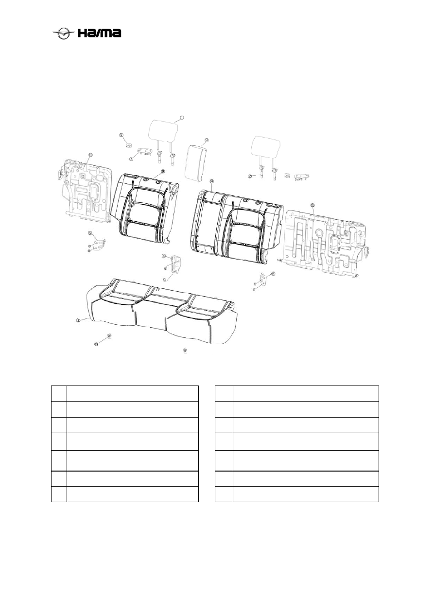
Disassembly/Assembly of Rear Seat 

1.  Perform the disassembly in the order shown in the table.  

2.     Perform the assembly in reverse order of the disassembly. 


1


Headrest


8


Seat back unlock button 


2


Headrest guide rod 


9


Rear seat back (right)


3


Seat cushion


 10

Rear seat back (left)


4


Rear seat back middle hinge 


 11

Rear seat back frame assembly (left)


5


Rear seat back hinge (left)


 12

Rear seat back frame assembly (right)


6


Rear seat back hinge (right)


 13

Plastic buckle


7


Seat back unlock trim cover 


14

Rear seat intermediate armrest


-------------------------------------------------------------------------------------------------------------------------------------------------------------


Electrical System 3D-1


Chapter 19 

Electrical System 

Table of Contents 

Electrical System······························································································· 3D-2 

Removal/Installation of Fuse ············································································· 3D-2 
Removal/Installation of Ignition Switch································································· 3D-2 
Checking the Ignition Switch ············································································· 3D-3 
Removal/Installation of Central Control Switch ······················································· 3D-3 
Removal/Installation of Clock Spring ··································································· 3D-4 
Disassembly/Assembly of Combination Switch ······················································· 3D-4 
Checking the Door Switch················································································· 3D-6 
Removal/Installation of Main Power Window Switch ················································ 3D-6 
Removal/Installation of Electric Rearview Mirror Switch············································ 3D-7 
Removal/Installation of Brake Lamp Switch ··························································· 3D-7 
Removal/Installation of Clutch Switch ·································································· 3D-7 

Vehicle Lighting System ······················································································ 3D-9 

Headlamps  ·································································································· 3D-9 
Front Turn Signal Lamp ··················································································· 3D-10 
Front Fog Lamps···························································································· 3D-10 
Daytime Running Lamps ·················································································· 3D-12 
Rear Combination Lamp··················································································· 3D-12 
Tail Trim Plate Lamp  ······················································································ 3D-13 
High-mounted Brake Lamp ··············································································· 3D-13 
License Plate Lamp························································································· 3D-14 
Rear Fog Lamps ···························································································· 3D-14 
Interior Lamp································································································ 3D-15 
Trunk Lamp ································································································· 3D-16 
Courtesy


Lamp······························································································ 3D-16 

Bulb Specification List ···················································································· 3D-17 

Wipers and Washers ·························································································· 3D-17 

Removal/Installation of Wiper Blade ···································································· 3D-17 

Combination Instrument ····················································································· 3D-21 

Removal/Installation of Combination Instrument······················································ 3D-21 
Speedometer ································································································· 3D-2721 
Tachometer ·································································································· 3D-2721 

Audio Assembly ································································································ 3D-25 

Audio system components················································································· 3D-25 
Diagnostic Information and Procedure of Audio system·············································· 3D-27 
Maintenance Instruction ··················································································· 3D-30 

Immobilizer System ··························································································· 3D-2733 

System Description ························································································· 3D-33 
Maintenance Instruction ··················································································· 3D-35 
Diagnostic Procedure······················································································· 3D-36 
DTC Analysis List ·························································································· 3D-37 

Rear Parking Assist System (RPAS) ······································································· 3D-2837 

System Loop Diagram ····················································································· 3D-38 
Removal/Installation of Radar Host······································································ 3D-39 
Analysis of Common Failures ············································································ 3D-39 

360° Panoramic Imaging System ··········································································· 3D-2840 

System Loop Diagram ····················································································· 3D-40 
Working Principles ························································································· 3D-42 
Analysis of Common Failures ············································································ 3D-44 

Reversing Camera ····························································································· 3D-2844 
Body Control Module (BCM) ··············································································· 3D-2844 

Failure analysis of BCM Control Unit··································································· 3D-50 

-------------------------------------------------------------------------------------------------------------------------------------------------------------


Electrical System 3D-2


Electrical System 

Precautions for Using Fuses  

After the blowout cause is determined and the fault 
is removed, replace the blown fuse with a new one 
of the specified rating. The fuse may blow out 
again if the fault is not removed before the 
replacement.  

Removal/Installation of Fuse 

1.  Remove the negative cable of the battery. 

2.  Remove the main fuse box cover. 

3.  Remove the bad fuse and replace it with a 

new one of the same rating. 

4.  The installation is in reverse order of the 

removal. 


Removal/Installation of Ignition Switch 

1.  Remove the negative cable of the battery. 

2.  Remove the steering column cover plate. 

3.  Perform the removal in the order shown in the 

table. 

4.  The installation is in reverse order of the 

removal. 


1


Connector 


2


Clamp bolt


3


Ignition switch


Ignition Switch Circuit Schematic 


Ignition Switch Circuit Schematic 


Electrical Diagram of Ignition Switch 
Connector 

-------------------------------------------------------------------------------------------------------------------------------------------------------------


Electrical System 3D-3


Checking the Ignition Switch 

1.  Remove the negative cable of the battery. 

2.  Remove the steering column cover plate. 

3.  Disconnect the ignition switch connector. 

4.  Use an ohmmeter to check the continuity 

between the wiring terminals of the ignition 
switch. If it does not comply with the 
technical requirements, replace the ignition 
switch.  


Removal/Installation of Cigar Lighter 

1.  Remove the negative cable of the battery. 

2.  Perform the removal in the order shown in the 

table. 

3.  The installation is in reverse order of the 

removal. 


1


Cigar lighter 


2


Cigar lighter socket


3


Cigar lighter illumination


Installation instruction for Cigar Lighter 
Socket 

Both need to ensure that the limit on the assembly 
lighter base boss (Figure 1) with a cigarette lighter 
illumination (Figure 2) alignment. 


Installation instruction for Cigar Lighter 
illumination 

Lighting a cigarette lighter upper limit column 
structure (Figure 1) and the upper limit holes in the 
panel, pressing down firmly on the lighting will 
snap two cards on the panel. 


Checking the Cigar Lighter  

1.  Turn the ignition switch to the ACC position. 

2.  Ensure the cigar lighter can be used after 

being pressed for 10-20s. 

3.  If the cigar lighter cannot be used normally, 

replace the cigar lighter socket. 

Removal/Installation of Central Control 
Switch 

1.  Remove the negative cable of the battery. 

2.     Remove the cigarette lighter panel. 

3.   Disconnect the control and switch the page to 

connect integrated switch connector. 

4.    The installation of sheet metal trunk lid switch 

snaps collapsed a little harder to remove the 
switch. 

5.  The installation is in reverse order of the 

removal. 


Needle


tool

 (catch 

splitter

-------------------------------------------------------------------------------------------------------------------------------------------------------------


Electrical System 3D-4


Removal/Installation of Clock 
Spring 

1.  Disconnect the negative cable of the battery. 

2.  Remove the driver side airbag module (Refer 

to the Removal/Installation of Driver Side 
Airbag Module, Section T). 

3.  Remove the steering wheel. (Refer to the 

Removal/Installation of Steering Wheel and 
Steering Column, Section N). 

4.  Remove the clock spring connector. 

5.  Remove 3 mounting screws.  

6.  Remove the clock spring. 

7.  The installation is in reverse order of the 

removal. 


Note: When removing and installing, be sure to 
straighten the front wheels, the steering wheel back 
to the positive. 

When installing, first around the clock spring 
clockwise (or counterclockwise) rotation in the end, 
and then around the counter clockwise (or 
clockwise) direction of rotation about three laps, 
then the clock will stop on the spring holes aligned 
to . 

Removal/Installation of Combination 
Switch 

1.  Disconnect the negative cable of the battery. 

2.  Remove the driver side airbag module (Refer 

to the Removal/Installation of Driver Side 
Airbag Module, Section T). 

3.  Remove the steering wheel. (Refer to the 

Removal/Installation of Steering Wheel and 
Steering Column, Section N). 

4.  Remove the steering column cover plate. 

5. Remove the clock spring. (Refer to 

Removal/Installation of Clock Spring, Section 
T). 

6.  Perform the removal in the order shown in the 

table. 

7.  The installation is in reverse order of the 

removal. 


1

Connector

2

Screw

3

Combination switch


Disassembly/Assembly of Combination 
Switch 


1


Screw 


2


Wiper and washer switch


3


Lighting switch


4


Combination switch body


Combination switch circuit schematics 


Limit hole 

-------------------------------------------------------------------------------------------------------------------------------------------------------------


Electrical System 3D-5


Combination switch on the light switch connector 
diagram 


Combination switch wiper switch connector 
diagram washing 


Removal/Installation of Hazard Warning 
Lamp Switch 

1.  Disconnect the negative cable of the battery. 

2.  Remove the instrument panel. 

3.  Pull it forward while pressing the hazard 

warning lamp switch to remove it.  

4.  Disconnect the hazard warning lamp switch 

connector. 

5.  Remove the hazard warning lamp switch. 

6.  The installation is in reverse order of the 

removal. 


Circuit Schematic for Hazard Warning Lamp 
Switch  


Hazard Warning Lamp Switch Connector 
Diagram (viewed from the wiring terminal) 


Removal/Installation of Left Switch Block 

1.  Disconnect the negative cable of the battery. 

2.     Remove the lower left panel on the left. 

3.     Unplug the connector left switch group. 

4.   The installation of the switch on the panel    

snaps a little harder to break apart and remove 
the left switch group. 

5.  The installation is in reverse order of the 

removal. 


Circuit Schematic for Left Switch Block 


-------------------------------------------------------------------------------------------------------------------------------------------------------------


Electrical System 3D-6


Removal/Installation of Door Switch  

1.  Disconnect the negative cable of the battery. 

2.  Perform the removal in the order shown in the 

table. 

3.  The installation is in reverse order of the 

removal.


1


Screw 


2


Door switch


3


Connector


Checking the Door Switch 

1.  Remove the door switch. 

2.  Use an ohmmeter to check the continuity 

between the door switch wiring terminal and 
the body ground. If it does not comply with 
the requirements, replace the door switch. 


Removal/Installation of Main Power 
Window Switch 

1.  Remove the negative cable of the battery. 

2.  Remove the instrument panel deputy. 

2.  Disconnect the main power window switch 

connector. 

3.  Use a screwdriver to remove 3 mounting 

screws. 

4.  The installation is in reverse order of the 

removal. 


Circuit Schematic for Main Power Window 

Switch 


Connector Diagram for Main Power Window 

Switch (viewed from the wiring terminal) 

Removal/Installation of Auxiliary Power 
Window Switch 

1.  Remove the negative cable of the battery. 

2.   Remove the rear door switch panel mounting 

screws. 

3.    Remove the rear door switch panel. 

Continuity

Switch 

position


Wiring terminal


Body ground

Tighten


Loosen


-------------------------------------------------------------------------------------------------------------------------------------------------------------


Electrical System 3D-7


4.  Disconnect the auxiliary power window 

switch connector. 

6.    Remove the power window switch vice. 

5.  Use a screwdriver to remove mounting screws. 

7.  The installation is in reverse order of the 

removal. 


Removal/Installation of Electric Rearview 
Mirror Switch 

1.  Remove the negative cable of the battery. 

2.     Remove sit down panel on the left. 

3.  Disconnect the electric rearview mirror switch 

connector. 

4.  The installation of the switch on the panel 

snaps a little harder to break apart and remove 
the switch. 

5.  The installation is in reverse order of the 

removal. 


Removal/Installation of Brake Lamp 
Switch 

1.  Remove the negative cable of the battery. 

2.  Remove the brake lamp switch connector. 

3.  The opening of 14 open-end wrench to loosen 

the locking bolt counterclockwise, and then 
hand the brake lamp switch rotated down 
from the nut hole of the brake pedal. 

4.  The installation is in reverse order of the 

removal. 


Removal/Installation of Clutch Switch 

1.  Remove the negative cable of the battery. 

2.  Remove the clutch switch connector. 

3.  Rotate the clutch switch counterclockwise by 

90° at the mounting position and take the 
clutch switch out of its mounting hole. 

4.  The installation is in reverse order of the 

removal. 


Removal/Installation of standby power 

1.  Remove the negative cable of the battery. 

2.     Remove the C-pillar trim. 

3.     Disconnect the standby power connector. 

4.     The installation of backup power supply on  

the panel collapsed a little harder to remove 
snap switch.


5.  The installation is in reverse order of the 

removal. 

Lock bolt

-------------------------------------------------------------------------------------------------------------------------------------------------------------


Electrical System 3D-8


Removal/Installation of trunk lid connect 
switch 

1.  Remove the negative cable of the battery. 

2.    Remove the rear door trim. 

3. Disconnect the trunk lid connect switch 


connector. 

4. The installation of sheet metal trunk lid switch 

snaps collapsed a little harder to remove the 
switch.


5.  The installation is in reverse order of the 

removal. 


Removal/Installation of high-pitch horn 
and low-pitch horn 

1.  Remove the negative cable of the battery. 

2.    Open the front cover, remove the front grille; 

3.    Disconnect the speaker wire connectors; 

4.    Remove the bolt with a tool; 

5.    Remove the speaker;


6.  The installation is in reverse order of the 

removal. 


High-pitch horn 


Low-pitch horn 
Removal/Installation of central electrical 
box bracket 

1.  Remove the negative cable of the battery. 

2.    Open the front cover, the buckle 1, 2 and snap-

snap 3 Loosen and remove the central 
electrical box; 

3.    Remove the bolt with a tool; 

4.    Remove the central electrical box bracket; 

5.  The installation is in reverse order of the 

removal. 


-------------------------------------------------------------------------------------------------------------------------------------------------------------


Electrical System 3D-9


Vehicle Lighting System 

Headlamps  
Removal/Installation of Front 
Combination Lamp 

1.  Remove the negative cable of the battery. 

2.  Remove the front grille, fender mounting 

plate, front bumper and headlight bracket. 

3.  Remove the snap fastener, bolt and nut clamp 

(2, 3 and 4). 

4.  Take out the lamp to the 20cm and remove the 

connector from the back of the lamp. 

5.  The installation is in reverse order of the 

removal. 

6.  Adjust the headlamp focusing. (Refer to 

Headlamp Focusing, Section T). 


1 Fender 

(left) 

2  Plastic lamp clamp MA10-61-275M1 

3 Bolt 

HQ90786-0620B 

4  Nut clamp HQ9YB31-0603 

5 Front 

combination 

lamp 

6  Upper cross member, radiator frame 

Headlamp Focusing 

1.  Adjust the tire pressure to the specified value. 

2.  Park the unloaded vehicle on the flat road.  

3.  Let one person sit on the driver seat.  

4.  Park the vehicle vertically to the wall.  

5.  Set the headlamps 3 m {10 ft} distant from 

the wall. 

6.  Remove the other headlamp’s connector when 

adjusting one headlamp.  

7.  Start the engine to charge the battery. 

8.  As shown in the figure, rotate the adjusting 

screw to adjust the headlamp (loosen and then 

tighten). 

Notice:If you tighten the screw and then loosen it, 
the adjusting screw will get looser in vehicle 
motion, resulting in inaccurate headlamp focusing. 


Removal/Installation of High/Low Beam 
Bulb 

Notice: Halogen bulbs will generate a lot of heat in 
use; if the lamp surface is dirty, the heat will 
continue to accumulate so as to shorten the lamp 
life. Hold the metal flange instead of the glass 
when replacing the lamp. 

1.  Remove the negative cable of the battery. 

2.  Remove the high beam/low beam connector.  

3.  Perform the removal in the order shown in the 

table. 

4.  The installation is in reverse order of the 

removal. 


Upward

Downward 

Outward  Inward 

-------------------------------------------------------------------------------------------------------------------------------------------------------------


Electrical System 3D-10


1


Lamp body


2


Bulb (H1 bulb for both high and low beams

3


Rear cover


4


Front combination lamp


Removal/Installation of Front Position 
Lamp Bulb 

1.  Open the engine compartment and remove the 

negative cable of the battery,unplug the 
headlamp connectors. 

2.  After removing the lamp, lamp light body 

position, remove the position light bulb. 

3.  Perform the installation in reverse order of the 

removal. 


1


Lamp body


2


Bulb, front turn signal lamp


3


Bulb socket


4 Rear 

cover 

Note: in the course, if there headlamp fog 
phenomenon, in the case of lighting, and can 
automatically dissipate within 30 minutes, which is 
a normal phenomenon.


Removal/Installation of Front Turn Signal 
Lamp 

1.  Disconnect the negative cable of the battery. 

2.  Remove the front bumper. 

3.  Remove the screw. 

4.  Remove the front turn signal lamp. 

5.  Perform the installation in reverse order of the 

removal. 


1


Screw (3)


2


Front turn signal lamp


3


Front bumper


Removal/Installation of Front Turn Signal 
Lamp Bulb 

1.  Remove the front turn signal lamp. 

2.  Unplug the lamp plug. 

3.  counterclockwise direction to unscrew the 

lamp bulb holder and remove. 

4.  Remove the light bulb replacement. 

5.  Perform the installation in reverse order of the 

removal. 


1


Rear cover


2


Bulb (21W)


3


Lamp body


Front Fog Lamps  

Removal/Installation of Front Fog Lamps  

1.  Disconnect the negative cable of the battery. 

2.  Remove the front bumper, remove the front 

fog lamps connectors. 

3.  Remove the screw. 

4.  Remove the front fog lamp. 

5.  Perform the installation in reverse order of the 

removal. 

-------------------------------------------------------------------------------------------------------------------------------------------------------------


Electrical System 3D-11


1


Screw (3)


2


Front fog lamp


3


Front bumper


Front Fog Lamp Focusing 

1.  Adjust the tire pressure to the specified value. 

2.  Park the unloaded vehicle on the flat road. 

3.  Let one person sit on the driver seat. 

4.  Park the vehicle 3 m {10 ft}distant in front of 

the white screen. 


5.  Cover up the other fog lamp when adjusting 

one.  

6.  Start the engine to charge the battery. 

7.  Turn on the front fog lamps. 

8.  As shown in the figure, rotate the adjusting 

bolt to adjust the bright area side line (loosen 
and then tighten). 

Notice:If you tighten the bolt and then loosen it, 
the adjusting screw will get looser in vehicle 
motion, resulting in inaccurate focusing of the 
front fog lamps.


Removal/Installation of Bulbs of Front 
Fog Lamps  

1.  Remove the front fog lamp. 

2.  Remove the front fog lamp trim cover. 

3. Bounce 

retainer. 

4. Unplug 

the 

bulb. 

5.  Unscrew the bulb of the front fog lamp (if 

equipped).  

6.  Perform the installation in reverse order of the 

removal. 


1


Rear cover


2


Bulb (H3)


3


Lamp body


Down 

Up

The left and right bolts 
are the same.


Fog lamp center


Bright zone side line

-------------------------------------------------------------------------------------------------------------------------------------------------------------


Electrical System 3D-12


Daytime Running Lamps  

Removal/Installation of Daytime Running 
Lamps  

1.  Disconnect the negative cable of the battery. 

2.  Remove the front bumper, remove the 

daytime running lamps connectors. 

3.  Remove the screw. 

4.  Remove the daytime running lamp. 

5.  Perform the installation in reverse order of the 

removal. 

Daytime running lamps repair 

The daytime running lamps for LED light source, 
if damaged, the need to replace the whole. 

Rear Combination Lamp  

Maintenance/Installation of Rear 
Combination Lamp  

1.  Remove the negative cable of the battery. 

2.  Remove the side trim plates of the trunk. 

3.  Remove the mounting nut from the rear 

combination lamp. 

4. Remove 

the 

connector. 

5.  Remove the rear combination lamp.  

6.  Perform the installation in reverse order of the 

removal. 


1


Plastic clip   Z00A4133012A


Plastic

 Nut  

HQ99910-0506


3 Self-tapping 

screws 


HQ99865-

0516B

Rear combination lamps snap 

FA1A-51-143 

Plastic lamp buckle  GA7B-51-
146L1 


6


Rear combination lamp


Notice:  

1. The waterproof gasket of the rear 

combination lamp can neither be replaced 
with other model, nor be ignored in the 
assembly, or else the leakage may be caused. 

2.  Please install the nuts in the order of 1-2-3, or 

else the protruding gap may be caused after 
assembly.  

3.  Don’t press the harness between the metal 

plate and the lamp; otherwise, the harness 
may be damaged easily resulting in bulb 
failure and even fire hazard.  


Maintenance/Installation of Bulbs 

1.  Remove the rear combination lamp.  

2.  Unscrew the bulb socket of the rear 

combination lamp and take it out. 

-------------------------------------------------------------------------------------------------------------------------------------------------------------


Electrical System 3D-13


3.  Remove and replace the bulb. 

4.  Perform the installation in reverse order of the 

removal. 


1 P21/5W 

bulb 

2 P21W 

bulb 

3 Lamp 

body 

4 Rear 

cover 

Tail Trim Plate Lamp 

Maintenance/Installation of Tail Trim 
Plate Lamp 

1.  Remove the negative cable of the battery. 

2.  Remove the mounting nut from the tail trim 

platelamp. 

3. Remove 

the 

connector. 

4.  Remove the tail trim platelamp.  

5.    Perform the installation in reverse order of the 

removal. 


1 Nut 

Back door assembly  

3 Lamp 

body 

Notice:  

1.  The waterproof sliver of the tail trim plate 

lamp can neither be replaced with other model, 
nor be ignored in the assembly, or else the 
leakage may be caused. 

2.  Don’t press the harness between the metal 

plate and the lamp; otherwise, the harness 
may be damaged easily resulting in bulb 
failure and even fire hazard. 

Removal/Installation of Tail Trim Plate 
Lamp Bulb 

1.  Remove the tail trim plate lamp. 

2.  Unscrew the lamp socket of the rear 

combination lamp and take it out. 

3.  Remove and replace the bulb. 

4. Perform the installation in reverse order of the 

removal. 


1 Lamp 

body 

2 W16W 

bulb 

3 Lamp 

socket 

High-mounted Brake Lamp  

Maintenance/Installation of High-
mounted Brake Lamp 

1.  Remove the negative cable of the battery. 

2.  Remove the back door inner trim plate. 

3. Remove 

the 

connector. 

4.     

Remove the


tail.


5.  Remove the mounting nut of the high-

mounted brake lamp. 

6.  Remove the high-mounted brake lamp. 

7.  Perform the installation in reverse order of the 

removal. 

-------------------------------------------------------------------------------------------------------------------------------------------------------------


Electrical System 3D-14


Nut 

High-mounted brake lamp 

Tail body 

Notice:  

The high-mounted brake lamp is of LED source, 
replace the lamp directly if it is broken. 

License Plate Lamp  

Removal/Installation of License Plate 
Lamp 

1.  Remove the negative cable of the battery. 

2.  On the outside of the car, license plate light 

shrapnel direction towards hard pressed, and 
pressed open. 

3.  Remove the license plate lamp. 

4. Remove 

the 

connector. 

5.  Perform the installation in reverse order of the 

removal. At this time, no screwdriver is 
needed for pressing.  


license plate lamp 

Back door assembly 

Maintenance of License Plate Lamp: 

This license plate lamp is of LED source, so please 
replace the lamp integrally if it is damaged.  

Rear Fog Lamps  

Removal/Installation of Rear Fog Lamps  

1.  Disconnect the negative cable of the battery. 

2.  Remove the rear bumper, remove the rear fog 

lamps connectors. 

3.  Remove the screw. 

4.  Remove the rear fog lamp. 

5.  Perform the installation in reverse order of the 

removal. 


Screw 

Rear fog lamp 

Rear bumper 

Removal/Installation of Front Rear Fog 
Lamps Bulb 

1.  Remove the rear fog lamp. 

2.  counterclockwise direction to unscrew the 

lamp bulb holder and remove. 

3.  Remove the light bulb replacement. 

4.  Perform the installation in reverse order of the 

removal. 


1 Lamp 

body 

2 21W 

bulb 

3 Lamp 

socket 


-------------------------------------------------------------------------------------------------------------------------------------------------------------


Electrical System 3D-15


Interior Lamp 

Removal/Installation of Front Reading 


Lamp (low version) 

1.  Remove the negative cable of the battery. 

2.  The reading lamp shade lamp body upturned 

former interior lights out with a slotted 
screwdriver. 

3.    Use a Phillips screwdriver to two self-tapping 

screws on the lamp housing removed. 

4. Remove 

the 

connector. 

5.  Perform the installation in reverse order of the 

removal.  


1 Reading 

lamp 

bracket 

2 Roof 

body 

Low distribution front reading lamps

4 Self-tapping 

screws 

5 Reading 

lamp 

shade 

Removal/Installation of Front Reading 


Lamp (High version with glasses box) 

1.  Remove the negative cable of the battery. 

2.  The reading lamp shade lamp body upturned 

former interior lights out with a slotted 
screwdriver. 

4.  Remove the connector. To replace the wick. 

5.  Perform the installation in reverse order of the 

removal.  


1 Roof 

body 


2 Body 

bracket 

Reading lamp bracket  

Front reading lamp body 

Front reading lamp wick 

Note: When the production assembly, the first line 
under the reading lamp light body frame fitted with 
front reading lights on the ceiling, then along the 
ceiling to install the lamp body stuck in the body 
iron bracket. Then plug in the connectors, the 
reading lamp wick fasten the lamp body. 

Removal/Installation of Rear Interior 
Lamp  (low version) 

1.  Remove the negative cable of the battery. 

2.    Dome lamp shade after Alice out with a slotted 

screwdriver. 

3. Use a Phillips screwdriver to attach the two lock 

bolts removed. 

4. Remove the connectors. 

5. Replace the rear interior lamps. 

After the ceiling bracket is glued to the ceiling, 
with the ceiling supplied together, contrary 
installation and removal order. 

-------------------------------------------------------------------------------------------------------------------------------------------------------------


Content      ..     5      6      7      8     ..