Haima 7. Air-intake System. Service Manual - part 6
 

  Index      Haima     Haima 7. Air-intake System. Service Manual


Search            copyright infringement  


Content      ..     4      5      6      7     ..


Haima 7. Air-intake System. Service Manual - part 6


General Precautions of EFI System Maintenance 

F-79 

Maintenance tips: 

The  malfunction  has  been  confirmed,  and  the 
following problems may possibly exist 

1)    Circuit  between  ECU  Pin  68#  and  cooling  fan 

relay Pin 85# short to ground. 

Maintenance tips: 

The  malfunction  is  not  ultimately  confirmed  and  it 
may  possibly  be  a  random  malfunction.  Inspect  the 
following items:   

1)    Examine  resistance  of  circuit  between  ECU  Pin 

68# and cooling fan relay Pin 85# 


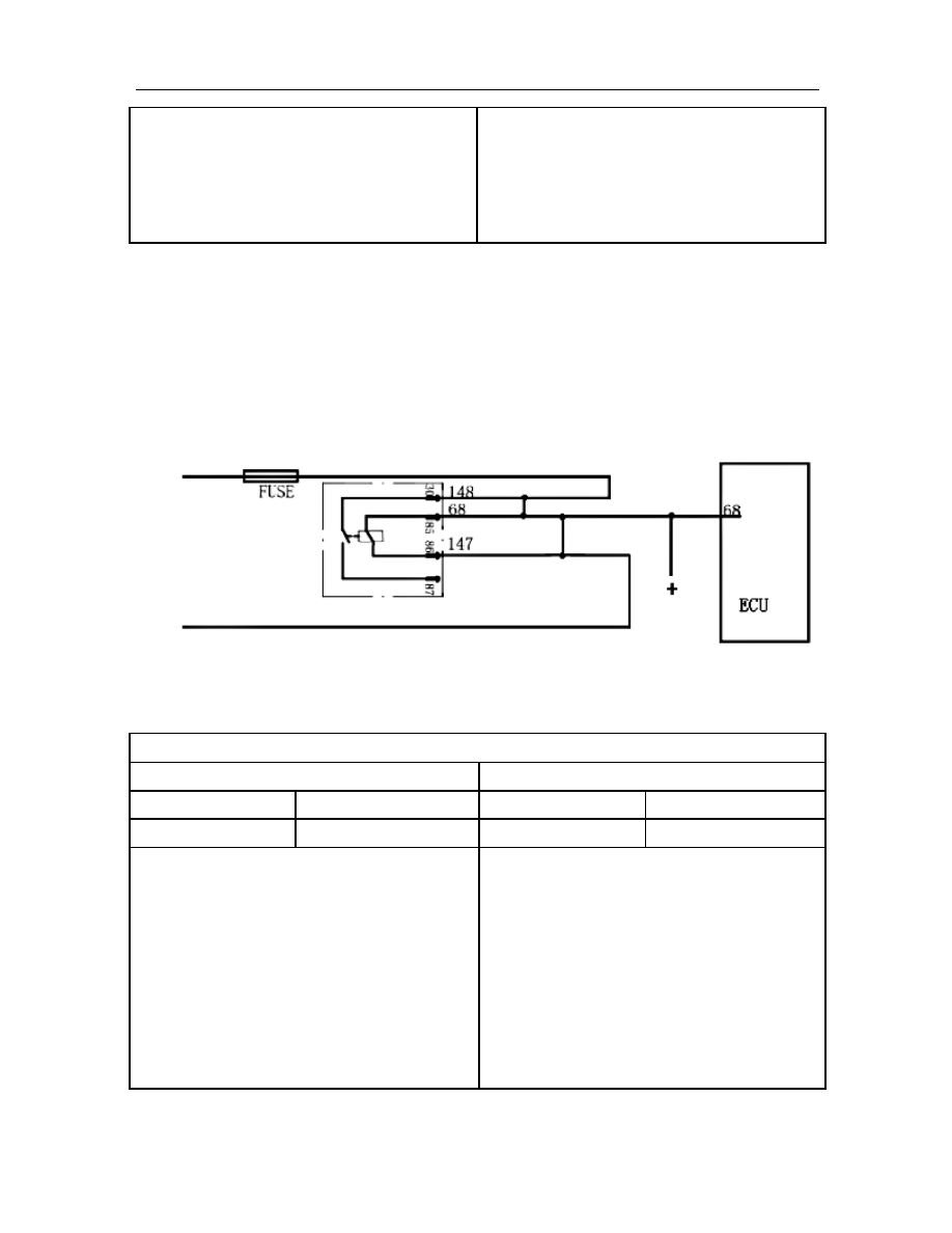
100. P0694 Control Circuit of Cooling Fan Relay Short to Power Supply (High Speed) 

Description about Malfunction Cause: 

After  engine  has  been  started,  circuit  control  module  of  ECU  examines  voltage  of  cooling  fan  circuit;  if  the 
value complies with the voltage of short-with-power malfunction mode, it is determined to be the malfunction 
of cooling fan circuit short to power supply. 

Schematic Circuit: 


Malfunction Diagnostic Guide: 

Required  Equipment:  (Diagnostic  Instrument  with  EOBD  Diagnostic  Function,  Digital  Multimeter,  and 
Correct Circuit Diagram) 

Step I: Use diagnostic instrument to read the malfunction information 

Read Result I 

Read Result II 

SVS lamp On 

P-CODE Present 

SVS lamp Off 

P-CODE Present 


P0694 


P0694 

Maintenance tips: 

The  malfunction  has  been  confirmed,  and  the 
following problems may possibly exist 

1)    Circuit  connected  with  ECU  Pin  68#  short  to 

circuit  between  cooling  fan  relay  Pin  86#  and 
power supply main relay. 

2)    Circuit  connected  with  ECU  Pin  68#  short  to 

circuit  between  cooling  fan  relay  Pin  30#  and 
positive battery pole. 

3)    Circuit  connected  with  ECU  Pin  68#  short  to 

other power circuit. 

Maintenance tips: 

The  malfunction  is  not  ultimately  confirmed  and  it 
may  possibly  be  a  random  malfunction.  Inspect  the 
following items:   

1)    Resistance between circuit connected with ECU 

Pin  68#  and  circuit  between  cooling  fan  relay 
Pin 86# and power supply main relay. 

2)    Resistance  between  ECU  Pin  68#  and  positive 

battery pole. 

3)    Resistance  between  ECU  Pin  68#  and  other 

power circuit. 


Battery 

Main relay 

-------------------------------------------------------------------------------------------------------------------------------------------------------------

General Precautions of EFI System Maintenance 

F-80 

101. P0704 Improper Clutch Pedal Switch Signal   

Description about Malfunction Cause: 

After  the  start  of  engine,  circuit  control  module  of  ECU  performs  monitoring  over  the  brake  switch  circuit 
voltage, and if the voltage exceeds the reasonable voltage range preset in ECU, this malfunction is reported.   

Schematic Circuit: 


Malfunction Diagnostic Guide: 

Required  Equipment:  (Diagnostic  Instrument  with  EOBD  Diagnostic  Function,  Digital  Multimeter,  and 
Correct Circuit Diagram) 

Step I: Use diagnostic instrument to read the malfunction information 

Read Result I 

Read Result II 


P-CODE Present 


P-CODE Present 


P0704 


P0704 

Maintenance tips: 

The  malfunction  has  been  confirmed,  and  the 
following problems may possibly exist 

1) 


Circuit  connected  to  Pin  74#  of  ECU  is  open, 
short to ground or power supply. 

Maintenance tips: 

The  malfunction  is  not  ultimately  confirmed  and  it 
may  possibly  be  a  random  malfunction.  Inspect  the 
following items:   

1) 


Resistance connected to Pin 68# of ECU 


102. P1336 Torque Limit Function of Electronic Throttle Security Monitoring   

Description about Malfunction Cause: 

ECU performs continuously monitoring over electronic throttle, including control over increase or decrease of 
torque. When ECU determines that the response of electronic throttle is due to outside interference rather than 
actual intention of driver, the limiting of engine torque is applied to ensure safe running of vehicle. 

C

lu

tc

h

 s

w

it

ch
 

-------------------------------------------------------------------------------------------------------------------------------------------------------------

General Precautions of EFI System Maintenance 

F-81 


Step I: Use diagnostic instrument to read the malfunction information 

Read Result I 

Read Result II 

SVS 灯 

P-CODE Present 

SVS 灯 

P-CODE Present 


P1336 


P1336 

Maintenance tips: 

The  malfunction  has  been  confirmed,  and  the 
following problems may possibly exist 

1)  Interference to harness exists; 

2)  Electronic throttle is already damaged and please 

replace it.   

Maintenance tips: 

The  malfunction  is  not  ultimately  confirmed  and  it 
may  possibly  be  a  random  malfunction.  Inspect  the 
following items:   

1) 


Interference to harness exists; 

2) 


Electronic  throttle  is  already  damaged  and 
please replace it. 


103. P1545 Deviation Between Actual and Target Position of Electronic Throttle Exceeding 
Limit Range   

Description about Malfunction Cause: 

The valve opening  of electronic throttle is controlled by  a  motor. When the deviation between the actual and 
target  opening  angle  exceeds  the  set  threshold,  the  air  intake  volume  shall  be  affected  directly,  further 
affecting power output of engine.   

Step I: Use diagnostic instrument to read the malfunction information 

Read Result I 

Read Result II 

SVS lamp 

P-CODE Present 

SVS lamp 

P-CODE Present 


P1545 


P1545 

Maintenance tips: 

The  malfunction  has  been  confirmed,  and  the 
following problems may possibly exist:   

1) 


Dirt exists in electronic throttle valve; 

2) 


Motor  inside  electronic  throttle  is  damaged, 
please replace it.   

Maintenance tips: 

The  malfunction  is  not  ultimately  confirmed  and  it 
may  possibly  be  a  random  malfunction.  Inspect  the 
following items:   

1) 


Remove dirt in valve; 

2) 


The  electronic  throttle  is  damaged,  please 
replace it.   


-------------------------------------------------------------------------------------------------------------------------------------------------------------

General Precautions of EFI System Maintenance 

F-82 

104. P1558 Too Large Resistance for Electronic Throttle Opening 

Description about Malfunction Cause: 

Dirt in electronic throttle shall result in this malfunction.   

Step I: Use diagnostic instrument to read the malfunction information 

Read Result I 

Read Result II 

SVS lamp 

P-CODE Present 

SVS lamp 

P-CODE Present 


P1545 


P1545 

Maintenance tips: 

The  malfunction  has  been  confirmed,  and  the 
following problems may possibly exist:   

1) 


Dirt exists in electronic throttle valve; 

2) 


The  electronic  throttle  is  damaged,  please 
replace it. 

Maintenance tips: 

The  malfunction  is  not  ultimately  confirmed  and  it 
may  possibly  be  a  random  malfunction.  Inspect  the 
following items:   

1) 


Remove dirt in valve; 

2) 


The  electronic  throttle  is  damaged,  please 
replace it. 

105. P1559 Self-learning Malfunction of Electronic Throttle 

Description about Malfunction Cause: 

When  the  key  is  switched  on,  each  part  of  electronic  control  system  shall  enter  into  self-learning  status  in 
accordance  with  system  preset  value,  and  after  the  termination  of  self-learning  period,  if  the  self-learning 
value  of  throttle  mismatch  the  preset  value,  this  malfunction  is  reported.  After  clearing  this  malfunction 
P-CODE,  switch  the  key  ON-OFF-ON  to  repeat  self-learning  process  for  several  times.  If  self-learning 
malfunction of electronic throttle is still reported, please replace the throttle with a new one. 

106. P1564 System Voltage for Electronic Throttle Self-learning Dissatisfied   

Description about Malfunction Cause: 

After  the  start  of  engine,  the  diagnostic  module  inside  ECU  performs  measurement  over  system  voltage. 
When  the  measured  voltage  cannot  satisfy  the  voltage  required  for  electronic  throttle  self-learning  process, 
this malfunction is reported. Under such circumstance, neither MIL lamp nor SVS lamp will be on. 

107. P1565 Self-learning Malfunction of Electronic Throttle Lower Limit Position 
Initiation   

Description about Malfunction Cause: 

When  the  key  is  switched  on,  each  part  of  electronic  control  system  shall  enter  into  self-learning  status  in 
accordance  with  system  preset  value,  and  after  the  termination  of  self-learning  period,  if  the  self-learning 
value  of  throttle  mismatch  the  preset  value,  this  malfunction  is  reported.  After  clearing  this  malfunction 
P-CODE,  switch  the  key  ON-OFF-ON  to  repeat  self-learning  process  for  several  times.  If  self-learning 
malfunction of electronic throttle lower limit position initiation is still reported, please replace the throttle with 
a new one.   

108. P1568 Too Large Resistance for Electronic Throttle Return   

Description about Malfunction Cause: 

Due  to  the  arrangement  of  electronic  throttle,  dirt  may  be  clotted  near  throttle  valve  at  mounting  site  under 
certain conditions, which causes too large resistance for return of valve.   

Step I: Use diagnostic instrument to read the malfunction information 

-------------------------------------------------------------------------------------------------------------------------------------------------------------

General Precautions of EFI System Maintenance 

F-83 

Read Result I 

Read Result II 

SVS Lamp 

P-CODE Present 

SVS Lamp 

P-CODE Present 


P1568 


P1568 

Maintenance tips: 

The  malfunction  has  been  confirmed,  and  the 
following problems may possibly exist:   

1) 


Dirt exists in electronic throttle valve; 

2) 


The  electronic  throttle  is  damaged,  please 
replace it. 

Maintenance tips: 

The  malfunction  is  not  ultimately  confirmed  and  it 
may  possibly  be  a  random  malfunction.  Inspect  the 
following items:   

1) 


Remove dirt in valve; 

2) 


The  electronic  throttle  is  damaged,  please 
replace it. 


109. P1579 Electronic Throttle Self-learning Condition Dissatisfied 

Description about Malfunction Cause: 

When  the  key  is  switched  on,  each  part  of  electronic  control  system  shall  enter  into  self-learning  status  in 
accordance  with  system  preset  value,  and  after  the  termination  of  self-learning  period,  if  the  self-learning 
value  of  throttle  mismatch  the  preset  value,  this  malfunction  is  reported.  After  clearing  this  malfunction 
P-CODE, switch  the  key ON-OFF-ON to repeat self-learning process for several times. If the  malfunction of 
electronic throttle self-learning condition dissatisfied is still reported, please check wire harness or replace the 
throttle with a new one when necessary.   

110. P1604 Self-learning Malfunction of Electronic Throttle Gain Control   

Description about Malfunction Cause: 

The status  of electronic throttle may change slightly during storage, transportation, assembly and application. 
When  the  key  is  switched  on,  each  part  of  electronic  control  system  shall  enter  into  self-learning  status  in 
accordance  with  system  preset  value,  and  after  the  termination  of  self-learning  period,  if  the  self-learning 
value  of  throttle  mismatch  the  preset  value,  this  malfunction  is  reported.  After  clearing  this  malfunction 
P-CODE,  switch  the  key  ON-OFF-ON  to  repeat  self-learning  process  for  several  times.  If  the  self-learning 
malfunction  of  electronic  throttle  gain  control  is  still  reported,  please  check  the  throttle  or  replace  it  with  a 
new one when necessary. 

111. P1610 Anti-theft Key without Code 

Description about Malfunction Cause: 

After engine has been started, when the anti-theft key  is diagnosed by the circuit control module inside ECU, 
this malfunction will appear when it is detected that the anti-theft key has not matched the code. 

-------------------------------------------------------------------------------------------------------------------------------------------------------------

General Precautions of EFI System Maintenance 

F-84 

Malfunction Diagnostic Guide: 

Required Equipment: (Diagnostic Instrument with EOBD Diagnostic Function) 

Step I: Use diagnostic instrument to read the malfunction information 

Read Result I 

Read Result II 

SVS lamp flickers 

P-CODE Present 

SVS lamp Off 

P-CODE Present 


P1610 


P1610 

Maintenance tips: 

The  malfunction  has  been  confirmed,  and  the 
following problems may possibly exist 

1)  The anti-theft key not matched. 

Maintenance tips: 

The  malfunction  is  not  ultimately  confirmed  and  it 
may  possibly  be  a  random  malfunction.  Inspect  the 
following items:   

1)  Whether  or  not  the  anti-theft  key  is  already 

matched. 


112. P1611 Key’ s Anti-theft Code Error 

Description about Malfunction Cause: 

After engine has been started, when the anti-theft key  is diagnosed by the circuit control module inside ECU, 
this malfunction will appear when the anti-theft code error is detected. 

Malfunction Diagnostic Guide: 

Required Equipment: (Diagnostic Instrument with EOBD Diagnostic Function) 

Step I: Use diagnostic instrument to read the malfunction information 

Read Result I 

Read Result II 

SVS Lamp On 

P-CODE Present 

SVS Lamp Off 

P-CODE Present 


P1611 


P1611 

Maintenance tips: 

The  malfunction  has  been  confirmed,  and  the 
following problems may possibly exist 

1) 

Anti-theft key error. 

2) 

Anti-theft key damaged. 

Maintenance tips: 

The  malfunction  is  not  ultimately  confirmed  and  it 
may  possibly  be  a  random  malfunction.  Inspect  the 
following items:   

1) 

Whether or not the anti-theft key is correct. 

2) 

Whether  or  not  the  anti-theft  key  is 

damaged 


-------------------------------------------------------------------------------------------------------------------------------------------------------------

General Precautions of EFI System Maintenance 

F-85 

113. P1612 Communication Between Anti-theft Device and ECU Disconnected 

Description about Malfunction Cause: 

In the case when engine is not started if the key is placed at “ON”, the anti-theft device will send messages to 
ECU for two times,  and  this  malfunction will  appear, when  ECU  has  failed to receive the  message  from the 
anti-theft device for the first time.   

Schematic Circuit: 


Malfunction Diagnostic Guide: 

Required Equipment: (Diagnostic Instrument with EOBD Diagnostic Function) 

Step I: Use diagnostic instrument to read the malfunction information 

Read Result I 

Read Result II 

SVS lamp flickers 

P-CODE Present 

SVS lamp Off 

P-CODE Present 


P1612 


P1612 

Maintenance tips: 

The  malfunction  has  been  confirmed,  and  the 
following problems may possibly exist 

1. 

The  communication  line  between  the  anti-theft 
device and the Pin 71# of ECU in open circuit 

2. 

The  communication  line  between  the  anti-theft 
device and the Pin 71# of ECU in bad contact 

3. 

The Pin 71# of ECU in bad contact 

Maintenance tips: 

The  malfunction  is  not  ultimately  confirmed  and  it 
may  possibly  be  a  random  malfunction.  Inspect  the 
following items:   

1. 

The  communication  line  between  the  anti-theft 
device and the Pin 71# of ECU 

2.    The contact of the Pin 71# of ECU. 


114. P1613 Communication Between Anti-theft Device and ECU Disconnected 

Description about Malfunction Cause: 

In the case when  engine is not started if the key is placed at “ON”, the anti-theft device will send message to 
ECU  for  two  times,  and  this  malfunction  will  appear  when  ECU  has  received  the  signal  from  the  anti-theft 
device for the first time, but failed to receive for the second time. 

Schematic Circuit: 

Anti-theft 

Device 

-------------------------------------------------------------------------------------------------------------------------------------------------------------

General Precautions of EFI System Maintenance 

F-86 


Malfunction Diagnostic Guide: 

Required Equipment: (Diagnostic Instrument with EOBD Diagnostic Function) 

Step I: Use diagnostic instrument to read the malfunction information 

Read Result I 

Read Result II 

SVS lamp flickers 

P-CODE Present 

SVS lamp Off 

P-CODE Present 


P1613 


P1613 

Maintenance tips: 

The  malfunction  has  been  confirmed,  and  the 
following problems may possibly exist 

4. 

The  communication  line  between  the  anti-theft 
device and the Pin 71# of ECU in open circuit 

5. 

The  communication  line  between  the  anti-theft 
device and the Pin 71# of ECU in bad contact 

6. 

The Pin 71# of ECU in bad contact 

Maintenance tips: 

The  malfunction  is  not  ultimately  confirmed  and  it 
may  possibly  be  a  random  malfunction.  Inspect  the 
following items:   

1. 

The  communication  line  between  the  anti-theft 
device and the Pin 71# of ECU 

2.    The contact of the Pin 71# of ECU. 


115. P1614 Malfunction of Chip Inside Anti-theft Key 

Description about Malfunction Cause: 

After  engine  has  been  started,  when  the  circuit  control  module  inside  ECU  performs  diagnosis  for  anti-theft 
key, this malfunction will appear when chip malfunction of the anti-theft key is detected. 

Malfunction Diagnostic Guide: 

Required Equipment: (Diagnostic Instrument with EOBD Diagnostic Function) 

Step I: Use diagnostic instrument to read the malfunction information 

Read Result I 

Read Result II 

SVS lamp flickers 

P-CODE Present 

SVS lamp Off 

P-CODE Present 


P1614 


P1614 

Maintenance tips: 

The  malfunction  has  been  confirmed,  and  the 
following problems may possibly exist 

1)  The Chip inside the anti-theft key damaged 

Maintenance tips: 

The  malfunction  is  not  ultimately  confirmed  and  it 
may  possibly  be  a  random  malfunction.  Inspect  the 
following items:   

1)  Whether  or  not  the  chip  inside  the  anti-theft  key 

is damaged 

Anti-theft 

Device 

-------------------------------------------------------------------------------------------------------------------------------------------------------------

General Precautions of EFI System Maintenance 

F-87 


116. P1651 Malfunction Indicator Lamp (SVS) Circuit Malfunction 

Description about Malfunction Cause: 

After engine has been started, the circuit voltage of SVS lamp is to be measured by the control module of SVS 
lamp circuit inside ECU, and when the voltage complies with the voltage in the mode of circuit malfunction, it 
is determined to be the circuit malfunction. 

Schematic Circuit: 


Malfunction Diagnostic Guide: 

Required  Equipment:  (Diagnostic  Instrument  with  EOBD  Diagnostic  Function,  Digital  Multimeter,  and 
Correct Circuit Diagram) 

Step I: Use diagnostic instrument to read the malfunction information 

Read Result I 

Read Result II 


P-CODE Present 


P-CODE Present 


P1651 


P1651 

Maintenance tips: 

The  malfunction  has  been  confirmed,  and 
the following problems may possibly exist 

1)  Circuit  connected  to  Pin  11#  of  ECU  is 
open; 

2)  Circuit  connected  to  Pin  11#  of  ECU  is 
short to ground; 

3)  Circuit  connected  to  Pin  11#  of  ECU  is 
short to power supply. 

Maintenance tips: 

The  malfunction  is  not  ultimately  confirmed  and  it  may 
possibly  be  a  random  malfunction.  Inspect  the  following 
items:   

1)  Measure  resistance  between  Pin  11#  of  ECU  and 
malfunction lamp;   

2) Measure resistance between Pin 11# of ECU and ground; 

3)  Measure  resistance  between  Pin  11#  of  ECU  and  ignition 
switch. 


Mian relay 

-------------------------------------------------------------------------------------------------------------------------------------------------------------

General Precautions of EFI System Maintenance 

F-88 

117. P2106 Electronic Throttle Driver Stage Malfunction   

Description about Malfunction Cause: 

After the start of engine, the driver stage diagnostic module inside ECU performs diagnosis over driver circuit 
of ECU. If the voltage of driver circuit exceeds reasonable voltage range, this malfunction is determined.   

Schematic Circuit: 


Malfunction Diagnostic Guide: 

Required  Equipment:  (Diagnostic  Instrument  with  EOBD  Diagnostic  Function,  Digital  Multimeter,  and 
Correct Circuit Diagram) 

Step I: Use diagnostic instrument to read the malfunction information 

Read Result I 

Read Result II 

MI lamp On 

P-CODE Present 

MI lamp off 

P-CODE Present 


P2106 


P2106 

Maintenance tips: 

The  malfunction  has  been  confirmed,  and  the 
following problems may possibly exist 

1)  Any  circuit  connected  to  Pins  64#,  65#,  66#  and 
67# of ECU is open, short to ground or power supply.   

Maintenance tips: 

The  malfunction  is  not  ultimately  confirmed  and  it 
may  possibly  be  a  random  malfunction.  Inspect  the 
following items:   

1)  Measure  resistance  between  Pin  64/65#  of  ECU 
and  Pin  4#  of  electronic  throttle,  power  supply  or 
ground.   

2)  Measure  resistance  between  Pin  66/67#  of  ECU 
and  Pin  1#  of  electronic  throttle,  power  supply  or 
ground.   


118. P2122 Too Low Signal Voltage of Electronic Throttle Pedal Position Sensor 1 

Description about Malfunction Cause: 

After  the  start  of  engine,  relevant  control  module  inside  ECU  performs  monitoring  over  circuit  voltage  of 
electronic throttle  pedal position sensor 1.  When the  voltage is below the lowest threshold  value preset, it is 
determined to be too low voltage malfunction.   

Schematic Circuit: 

-------------------------------------------------------------------------------------------------------------------------------------------------------------

General Precautions of EFI System Maintenance 

F-89 


Malfunction Diagnostic Guide: 

Required  Equipment:  (Diagnostic  Instrument  with  EOBD  Diagnostic  Function,  Digital  Multimeter,  and 
Correct Circuit Diagram) 

Step I: Use diagnostic instrument to read the malfunction information 

Read Result I 

Read Result II 

MI lamp On 

P-CODE Present 

MI lamp off 

P-CODE Present 


P2122 


P2122 

Maintenance tips: 

The  malfunction  has  been  confirmed,  and  the 
following problems may possibly exist 

1) 


Short  circuit  between  Pin  16#  of  ECU  and  Pin 
36#; 

2) 


Circuit connected  to Pin 16#  of ECU shorted  to 
ground. 

Maintenance tips: 

The  malfunction  is  not  ultimately  confirmed  and  it 
may  possibly  be  a  random  malfunction.  Inspect  the 
following items:   

1) 


Measure resistance between Pin 16# of ECU and 
Pin 36#; 

2) 


Measure resistance between Pin 16# of ECU and 
ground. 


119. P2123 Too High Signal Voltage of Electronic Throttle Pedal Position Sensor 1 

Description about Malfunction Cause: 

After  the  start  of  engine,  relevant  control  module  inside  ECU  performs  monitoring  over  circuit  voltage  of 
electronic throttle pedal position sensor 1.  When  the  voltage is above the highest threshold value preset, it is 
determined to be too high voltage malfunction. 

Schematic Circuit: 


-------------------------------------------------------------------------------------------------------------------------------------------------------------

General Precautions of EFI System Maintenance 

F-90 

Malfunction Diagnostic Guide: 

Required  Equipment:  (Diagnostic  Instrument  with  EOBD  Diagnostic  Function,  Digital  Multimeter,  and 
Correct Circuit Diagram) 

Step I: Use diagnostic instrument to read the malfunction information 

Read Result I 

Read Result II 

MI lamp On 

P-CODE Present 

MI lamp off 

P-CODE Present 


P2123 


P2123 

Maintenance tips: 

The  malfunction  has  been  confirmed,  and  the 
following problems may possibly exist 

1) 


Short  circuit  between  Pin  16#  of  ECU  and  Pin 
33#; 

2)


Circuit connected  to Pin 16#  of ECU shorted  to 
other power supply. 


Maintenance tips: 

The  malfunction  is  not  ultimately  confirmed  and  it 
may  possibly  be  a  random  malfunction.  Inspect  the 
following items:   

1)


Measure resistance between Pin 16# of ECU and 
Pin 33#; 

2) 


Measure resistance between Pin 16# of ECU and 
other power supply. 


120. P2127 Too Low Signal Voltage of Electronic Throttle Pedal Position Sensor 2 

Description about Malfunction Cause: 

After  the  start  of  engine,  relevant  control  module  inside  ECU  performs  monitoring  over  circuit  voltage  of 
electronic throttle  pedal position sensor 2.  When the  voltage is below the lowest threshold  value preset, it is 
determined to be too low voltage malfunction. 

Schematic Circuit: 


-------------------------------------------------------------------------------------------------------------------------------------------------------------

General Precautions of EFI System Maintenance 

F-91 

Malfunction Diagnostic Guide: 

Required  Equipment:  (Diagnostic  Instrument  with  EOBD  Diagnostic  Function,  Digital  Multimeter,  and 
Correct Circuit Diagram) 

Step I: Use diagnostic instrument to read the malfunction information 

Read Result I 

Read Result II 

MI lamp On 

P-CODE Present 

MI lamp off 

P-CODE Present 


P2127 


P2127 

Maintenance tips: 

The  malfunction  has  been  confirmed,  and  the 
following problems may possibly exist 

1)


Short  circuit  between  Pin  40#  of  ECU  and  Pin 
35#; 

2) 


Circuit connected  to Pin 40#  of ECU shorted  to 
ground. 

Maintenance tips: 

The  malfunction  is  not  ultimately  confirmed  and  it 
may  possibly  be  a  random  malfunction.  Inspect  the 
following items:   

1) 


Measure resistance between Pin 40# of ECU and 
Pin 35#; 

2) 


Measure resistance between Pin 40# of ECU and 
ground.   


121. P2128 Too High Signal Voltage of Electronic Throttle Pedal Position Sensor 2 

Description about Malfunction Cause: 

After  the  start  of  engine,  relevant  control  module  inside  ECU  performs  monitoring  over  circuit  voltage  of 
electronic throttle pedal position sensor 2.  When  the  voltage is above the highest threshold value preset, it is 
determined to be too high voltage malfunction.   

Schematic Circuit: 


-------------------------------------------------------------------------------------------------------------------------------------------------------------

General Precautions of EFI System Maintenance 

F-92 

Malfunction Diagnostic Guide: 

Required  Equipment:  (Diagnostic  Instrument  with  EOBD  Diagnostic  Function,  Digital  Multimeter,  and 
Correct Circuit Diagram) 

Step I: Use diagnostic instrument to read the malfunction information 

Read Result I 

Read Result II 

MI lamp On 

P-CODE Present 

MI lamp off 

P-CODE Present 


P2128 


P2128 

Maintenance tips: 

The  malfunction  has  been  confirmed,  and  the 
following problems may possibly exist 

1) Short circuit between Pin 40# of ECU and Pin 
32#; 

2)  Circuit  connected  to  Pin  40#  of  ECU  shorted 
to other power supply.   

Maintenance tips: 

The  malfunction  is  not  ultimately  confirmed  and  it  may 
possibly  be  a  random  malfunction.  Inspect  the  following 
items:   

1)  Measure  resistance  between  Pin  40#  of  ECU  and  Pin 
32#; 

2)  Measure resistance between Pin 40# of ECU and  other 
power supply.   


122. P2138 Electronic Throttle Pedal Position Sensor Signal Irrational   

Description about Malfunction Cause: 

After  the  start  of  engine,  relevant  control  module  inside  ECU  performs  monitoring  over  circuit  voltage  of 
electronic throttle pedal position sensor 1/2. When the voltage is beyond the rational voltage range preset, it is 
determined to be irrational voltage signal malfunction.   

Schematic Circuit: 


Malfunction Diagnostic Guide: 

Required  Equipment:  (Diagnostic  Instrument  with  EOBD  Diagnostic  Function,  Digital  Multimeter,  and 
Correct Circuit Diagram) 


-------------------------------------------------------------------------------------------------------------------------------------------------------------

General Precautions of EFI System Maintenance 

F-93 

Step I: Use diagnostic instrument to read the malfunction information 

Read Result I 

Read Result II 


P-CODE Present 


P-CODE Present 


P2138 


P2138 

Maintenance tips: 

The  malfunction  has  been  confirmed,  and  the 
following problems may possibly exist 

1) Open circuit between  Pin 33#  of ECU and  Pin 2# 
of throttle pedal; 

2) Open circuit between  Pin 40#  of ECU and  Pin 6# 
of throttle pedal. 

Maintenance tips: 

The  malfunction  is  not  ultimately  confirmed  and  it 
may  possibly  be  a  random  malfunction.  Inspect  the 
following items:   

1)  Measure  resistance  between  Pin  33#  of  ECU  and 
2# Pin of throttle pedal; 

2)  Measure  resistance  between  Pin  40#  of  ECU  and 
Pin 6# of throttle pedal. 


123. 

P2177  Air-Fuel  Ratio  for  Self-Learning  Value  under  Closed-Loop  Control 

Exceeding Upper Limit (Mid-Load Area) 

Description about Principle and Malfunction Cause: 

In  order to  optimize the integrated  transformation efficiency  of  catalytic  converter  to  HC,  CO, and NOx, the 
air-fuel ratio of the mixed gas shall be controlled at 14.7:1. If it is found the deviation in manufacture of parts, 
the  sedimentation  of  colloidal  matters  in  gasoline  on  the  fuel  injector,  the  air  intake  pipeline,  or  the  back  of 
valve, and air leakage exists with intake and exhaust system, all these factors will give rise to a deviation from 
14.7:1  in  the  air-fuel  ratio  to  different  degrees  (rich  or  lean),  which  will  lead  to  deteriorated  emission  and 
reduction in engine performance. 

The engine  control system is  able to  make amendments and self-learning  on  fuel injection volume according 
to the degree and characteristic of deviation in air-fuel ratio. The self-learning of deviation in air-fuel ratio is 
divided  into  “Self-learning in Small  Load Area” and “Self-learning  in  Medium  Load  Area”. The system will 
determine  it  to  be  the  malfunction  of  lean  mixed  gas,  when  self-learning  in  medium  load  area  reaches  the 
upper limit value set by the system (lean mixed gas, and the system continuously increasing the fuel injection 
volume up to the maximum value). 

Malfunction Diagnostic Guide: 

Required Equipment: (Diagnostic Instrument with EOBD Diagnostic Function) 

Step I: Use diagnostic instrument to read the malfunction information 

Read Result I 

Read Result II 

MIL Lamp On 

P-CODE Present 

MIL Lamp Off 

P-CODE Present 


P2177 


P2177 

Maintenance tips: 

The  malfunction  has  been  confirmed,  and  the 
following problems may possibly exist 

1) 

Fuel injector blocked and cleaning required 

2) 

Air leakage with intake and exhaust system 

3) 

Excessive  sedimentation  of  colloidal  matter  in 
air intake pipeline or on the back of intake valve 
and cleaning required 

4) 

Deviation in parts of engine   

Maintenance tips: 

The  malfunction  has  not  been  finally  confirmed. 
Please wait for system to fulfill diagnosis. 

-------------------------------------------------------------------------------------------------------------------------------------------------------------

General Precautions of EFI System Maintenance 

F-94 

124. 

P2178  Air-Fuel  Ratio  for  Self-Learning  Value  under  Closed-Loop  Control 

Exceeding Lower Limit (Medium Load Area) 

Description about Principle and Malfunction Cause: 

In  order to  optimize the integrated  transformation efficiency  of  catalytic  converter  to  HC,  CO, and NOx, the 
air-fuel ratio of the mixed gas shall be controlled at 14.7:1. If it is found the deviation in manufacture of parts, 
the  sedimentation  of  colloidal  matters  in  gasoline  on  the  fuel  injector,  the  air  intake  pipeline,  or  the  back  of 
valve, and air leakage exists with intake and exhaust system, all these factors will give rise to a deviation from 
14.7:1  in  the  air-fuel  ratio  to  different  degrees  (rich  or  dense),  which  will  lead  to  deteriorated  emission  and 
reduction in engine performance. 

The engine  control system is  able to  make amendments and self-learning  on  fuel injection volume according 
to the degree and characteristic of deviation in air-fuel ratio. The self-learning of deviation in air-fuel ratio is 
divided  into  “Self-learning in Small  Load Area” and “Self-learning  in  Medium  Load  Area”. The system will 
determine  it  to  be  the  malfunction  of  rich  mixed  gas,  when  self-learning  in  medium  load  area  reaches  the 
lower limit value set by the system (rich mixed gas, and the system continuously decreasing the fuel injection 
volume up to the minimum value). 

Malfunction Diagnostic Guide: 

Required Equipment: (Diagnostic Instrument with EOBD Diagnostic Function) 

Step I: Use diagnostic instrument to read the malfunction information 

Read Result I 

Read Result II 

MIL Lamp On 

P-CODE Present 

MIL Lamp Off 

P-CODE Present 


P2178 


P2178 

Maintenance tips: 

The  malfunction  has  been  confirmed,  and  the 
following problems may possibly exist 

1) 

Colloidal  matter  present  inside  fuel  injector 
slowing  down  the  turn-off  of  fuel  injector  and 
cleaning required 

2) 

Air leakage with intake valve 

3) 

Deviation in valve clearance 

4) 

Deviation in parts of engine 

5) 

Fuel pressure too high   

Maintenance tips: 

The  malfunction  has  not bee  finally confirmed, and 
wait for system to fulfill diagnosis. 


125. 

P2187  Air-Fuel  Ratio  for  Self-learning  Value  under  Closed-Loop  Control 

Exceeding Upper Limit (Low Load Area) 

Description about Principle and Malfunction Cause: 

In  order to  optimize the integrated  transformation efficiency  of  catalytic  converter  to  HC,  CO, and NOx, the 
air-fuel ratio of the mixed gas shall be controlled at 14.7:1. If it is found the deviation in manufacture of parts, 
the  sedimentation  of  colloidal  matters  in  gasoline  on  the  fuel  injector,  the  air  intake  pipeline,  or  the  back  of 
valve, and air leakage exists with intake and exhaust system, all these factors will give rise to a deviation from 
14.7:1  in  the  air-fuel  ratio  to  different  degrees  (rich  or  lean),  which  will  lead  to  deteriorated  emission  and 
reduction in engine performance. 

The engine  control system is  able to  make amendments and self-learning  on  fuel injection volume according 
to the degree and characteristic of deviation in air-fuel ratio. The self-learning of deviation in air-fuel ratio is 
divided  into  “Self-learning in Small  Load Area” and “Self-learning  in  Medium  Load  Area”. The system will 

-------------------------------------------------------------------------------------------------------------------------------------------------------------


Content      ..     4      5      6      7     ..