Haima 7. Air-intake System. Service Manual - part 4
 

  Index      Haima     Haima 7. Air-intake System. Service Manual


Search            copyright infringement  


Content      ..     2      3      4      5     ..


Haima 7. Air-intake System. Service Manual - part 4


General Precautions of EFI System Maintenance 

F-49 

2. 

The  rotational  speed  signal  may  be  detected  but  the  crankshaft  software  reference  point  signal  (BM) 
cannot be detected. 

3. 

The crankshaft software reference point signal (BM) is frequently missing. 

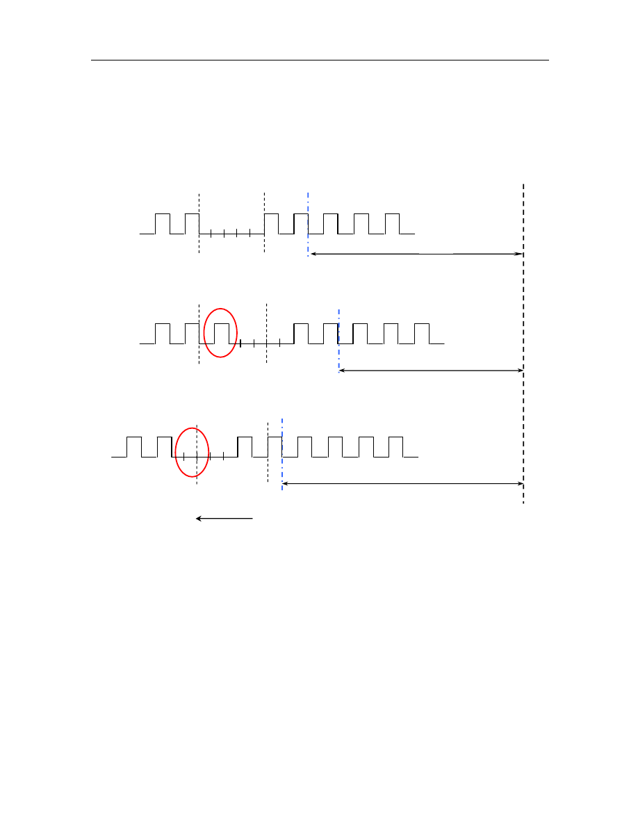
The  schematic  diagram  for  the  crankshaft  software  reference  point  signal  (BM)  frequently  found  before  or 
behind the expected position is given as follows: 


1. Correct Situation

2. Spacing of Large Tooth Delayed by the Time of One Tooth than Nominal Position→ One Tooth More 

  BM 

Inductive Gear Ring Rotating Direction


  TDC 

  BM 

106º 

  BM 

To be Adjusted by Minus One tooth in Next Segment


To be Adjusted by Adding One Tooth in Next Segment 

-------------------------------------------------------------------------------------------------------------------------------------------------------------

General Precautions of EFI System Maintenance 

F-50 

Malfunction Diagnostic Guide: 

Required  Equipment:  (Diagnostic  Instrument  with  EOBD  Diagnostic  Function,  Digital  Multimeter,  and 
Correct Circuit Diagram) 

Step I: Use diagnostic instrument to read the malfunction information 

Read Result I 

Read Result II 

MIL Lamp On 

P-CODE Present 

MIL Lamp Off 

P-CODE Present 


P0321 


P0321 

Maintenance tips: 

The  malfunction  has  been  confirmed,  and  the 
following problems may possibly exist 

1) 


Random  short  circuit  or  open  circuit  with  line 
connection 

Maintenance tips: 

As  the  malfunction  itself  is  caused  by  random  short 
circuit  or  open  circuit,  diagnosis  is  not  required 
before  it  has  been  finally  confirmed,  and  wait  for 
system self confirmation. 

61.  P0322 Missing of Speed Sensor Impulse Signal (Open or Short Circuit) 

Description about Malfunction Cause: 

After engine has been started, ECU performs monitoring over the rotational speed sensor signal and the phase 
sensor signal at the same time. If the signals of the phase sensor may be continuously obtained, but the signals 
of the rotational speed sensor cannot be received, the system will determine that the signals of rotational speed 
sensor are missing.   

Schematic Diagram: 


Malfunction Diagnostic Guide: 

Required  Equipment:  (Diagnostic  Instrument  with  EOBD  Diagnostic  Function,  Digital  Multimeter,  and 
Correct Circuit Diagram) 

Step I: Use diagnostic instrument to read the malfunction information 

Read Result I 

Read Result II 

MIL Lamp On 

P-CODE Present 

MIL Lamp Off 

P-CODE Present 


P0322 


P0322 

Maintenance tips: 

The  malfunction  has  been  confirmed,  and  the 
following problems may possibly exist 

1) 


The  circuit  of rotational  speed sensor connected 
to the Pin 15# of ECU in open circuit 

2)    The  circuit  of rotational  speed sensor connected 

to the Pin 34# of ECU in open circuit 

3) 

The  coil  of  rotational  speed  sensor  in  open 
circuit 

Maintenance tips: 

The  malfunction  is  not  ultimately  confirmed  and  it 
may  possibly  be  a  random  malfunction.  Inspect  the 
following items:   

1) 

The electric resistance of rotational speed sensor 
connected to the Pin 15# of ECU 

2) 

The  electric  resistance  for  the  circuit  of 
rotational  speed  sensor  connected  to  the  Pin  3# 
of ECU 

3) 

The  electric  resistance  of  coil  for  rotational 
speed sensor 

-------------------------------------------------------------------------------------------------------------------------------------------------------------

General Precautions of EFI System Maintenance 

F-49 

62.  P0327 Circuit Voltage of Knock Sensor Signal Too low 

Description about Malfunction Cause: 

The  knock  sensor  is  installed  on  the  engine  body.  The  engine  vibrates  in  different  frequency  of  vibration 
under  different  operating  conditions,  and  generates  voltage  signals  containing  various  frequencies.  The 
voltage  signal  may  not  only  reflect  whether  or  not  the  engine  has  experienced  knock  but  also  reflect  the 
background noise value of the engine (the noise of  mechanical parts). When the engine is operating normally 
and  the  knock  sensor  is  working  normally,  the  background  noise  value  will  fluctuate  within  the  specified 
range.  Once  the  background  noise  value  is  lower  than  the  set  threshold,  the  system  then  believes  that 
malfunction exists in the signal circuit of the knock sensor. 

Schematic Diagram:   


Malfunction Diagnostic Guide: 

Required Equipment: (Diagnostic Instrument with EOBD Diagnostic Function) 

Step I: Use diagnostic instrument to read the malfunction information 

Read Result I 

Read Result II 

MIL Lamp On 

P-CODE Present 

MIL Lamp Off 

P-CODE Present 


P0327 


P0327 

Maintenance tips: 

The  malfunction  has  been  confirmed,  and  the 
following problems may possibly exist 

1) 

The circuit  for the Pin 19# of ECU connected to 
the Pin 1# of knock sensor in open circuit 

2) 

The circuit  for the Pin 20# of ECU connected to 
the Pin 2# of knock sensor in open circuit 

3) 

The  circuit  for  the  Pin  19#  of  ECU  short  to 
ground 

4) 

The  circuit  for  the  Pin  20#  of  ECU  short  to 
ground 

Maintenance tips: 

The  malfunction  has  not  been  finally  confirmed,  and 
examine the following items: 

1) 

Inspect  the  electric  resistance  of  the  circuit  for 
the  Pin  19#  of  ECU  connected  to  the  Pin  1#  of 
knock sensor. 

2) 

Inspect  the  electric  resistance  of  the  circuit  for 
the  Pin  20#  of  ECU  connected  to  the  Pin  2#  of 
knock sensor. 

3) 

Inspect the  electric  resistance  for the  Pin 19#  of 
ECU to ground. 

4) 

Inspect  the electric  resistance  for the Pin 20# of 
ECU to ground. 


-------------------------------------------------------------------------------------------------------------------------------------------------------------

General Precautions of EFI System Maintenance 

F-50 

63.   

P0328 High signal circuit voltage of shock sensor 

Description about Malfunction Cause: 

The  knock  sensor  is  installed  on  the  engine  body.  The  engine  vibrates  in  different  frequency  of  vibration 
under  different  operating  conditions,  and  generates  voltage  signals  containing  various  frequencies.  The 
voltage  signal  may  not  only  reflect  whether  or  not  the  engine  has  experienced  knock  but  also  reflect  the 
background noise value of the engine (the noise of  mechanical parts). When the engine is operating normally 
and  the  knock  sensor  is  working  normally,  the  background  noise  value  will  fluctuate  within  the  specified 
range.  Once  the  background  noise  value  is  lower  than  the  set  threshold,  the  system  then  believes  that 
malfunction exists with the mechanical parts of the engine. 

Malfunction Diagnostic Guide: 

Required Equipment: (Diagnostic Instrument with EOBD Diagnostic Function) 

Step I: Use diagnostic instrument to read the malfunction information 

Read Result I 

Read Result II 

MIL Lamp On 

P-CODE Present 

MIL Lamp Off 

P-CODE Present 


P0328 


P0328 

Maintenance tips: 

The malfunction has been confirmed, and the following 
problems may possibly exist 

1)  Serious  wear  on  some  parts  of  engine,  and 

mechanical parts of engine (piston ring, piston pin, 
bearing  bush,  and  clearance  between  parts,  etc)  to 
be inspected 

Maintenance tips: 

The  malfunction  has  not  been  finally  confirmed, 
and wait for the system to fulfill self-diagnosis.   


64.  P0340 Phase Sensor Installation Position Improper 

Description about Malfunction Cause: 

The  operation  principle  for  phase sensor is  to  use  a Hall  component  to  induce a signal wheel  to rotate along 
with  the  camshaft,  thus  to  monitor  the  position  of  camshaft.  The  phase  signal  received  by  ECU  shall  be 
changing alternately on a regular basis between the high level and the low level, and ECU shall determine that 
malfunction exists with the phase signal, when only slow change in high and low levels is detected. 

Schematic Diagram: 


-------------------------------------------------------------------------------------------------------------------------------------------------------------

General Precautions of EFI System Maintenance 

F-51 

Malfunction Diagnostic Guide: 

Required  Equipment:  (Diagnostic  Instrument  with  EOBD  Diagnostic  Function,  Digital  Multimeter,  and 
Correct Circuit Diagram) 

Step I: Use diagnostic instrument to read the malfunction information 

Read Result I 

Read Result II 

MIL Lamp On 

P-CODE Present 

MIL Lamp Off 

P-CODE Present 


P0340 


P0340 

Maintenance tips: 

The  malfunction  has  been  confirmed,  and  the 
following problems may possibly exist 

1) 

The  installation  position  of  phase  sensor 
improper A 

2) 

The  connector  for  wire  harness  of  phase  sensor 
A not properly connected 

Maintenance tips: 

The  malfunction  is  not  ultimately  confirmed  and  it 
may  possibly  be  a  random  malfunction.  Inspect  the 
following items:   

1) 

The  installation  position  of  phase  sensor  A 
(angle,  and  the  clearance  with  phase  trigger 
wheel) 

2) 

The connection of connector for wire harness of 
phase  sensor  A  (biting  force  of  pin,  and 
oxidation status of pin) 


65.   

P0341 Phase Sensor Bad Contact 

Decription about Malfunction Cause: 

The  operation  principle  for  phase  sensor  is  to  use  Hall  component  to  induce  a  triggered  wheel  that  rotates 
along  with  the  camshaft,  thus  to  monitor  the  position  of  the  camshaft.  The  phase  signals  received  by  ECU 
shall  be  changing  alternately  on  a  regular  basis  between  high  level  and  low  level,  and  ECU  shall  determine 
that malfunction exists with phase signal if irregular phase changing signal is detected. 

Schematic Circuit:   


Malfunction Diagnostic Guide: 

Required  Equipment:  (Diagnostic  Instrument  with  EOBD  Diagnostic  Function,  Digital  Multimeter,  and 
Correct Circuit Diagram) 


Characteristic 

curve 

Signal of 

crankshaft 

sensor 

Signal of phase 

sensor 

-------------------------------------------------------------------------------------------------------------------------------------------------------------

General Precautions of EFI System Maintenance 

F-52 

Step I: Use diagnostic instrument to read the malfunction information 

Read Result I 

Read Result II 

MIL Lamp On 

P-CODE Present 

MIL Lamp Off 

P-CODE Present 


P0341 


P0341 

Maintenance tips: 

The  malfunction  has  been  confirmed,  and  the 
following problems may possibly exist 

1) 


The  connector  for  wire  harness  of  phase  sensor 
A not properly connected 

Maintenance tips: 

The  malfunction  is  not  ultimately  confirmed  and  it 
may  possibly  be  a  random  malfunction.  Inspect  the 
following items:   

1) 


The connection of connector for wire harness of 
phase sensor A(biting force of pin, and oxidation 
status of pin) 

66.   

P0342 Phase Sensor Short to Ground 

Description about Malfunction Cause: 

The  operation  principle  for  phase  sensor  is  to  use  Hall  component  to  induce  a  triggered  wheel  that  rotates 
along with the camshaft, thus to monitor the position of camshaft. The phase signals received by ECU shall be 
changing alternately on a regular basis between high level and low level, and ECU shall determine the circuit 
of phase signal to be short to ground if phase signals located at low level are successively detected。 

Schematic Circuit: 


Malfunction Diagnostic Guide: 

Required  Equipment:  (Diagnostic  Instrument  with  EOBD  Diagnostic  Function,  Digital  Multimeter,  and 
Correct Circuit Diagram) 

Step I: Use diagnostic instrument to read the malfunction information 

Read Result I 

Read Result II 

MIL Lamp On 

P-CODE Present 

MIL Lamp Off 

P-CODE Present 


P0342 


P0342 

Maintenance tips: 

The  malfunction  has  been  confirmed,  and  the 
following problems may possibly exist 

1)    The circuit connected to the Pin 79# of ECU and 

the Pin 1# of phase sensor in short circuit 

2) 

The circuit connected to the Pin 79# of ECU and 
the ground in short circuit。 

Maintenance tips: 

The  malfunction  is  not  ultimately  confirmed  and  it 
may  possibly  be  a  random  malfunction.  Inspect  the 
following items:   

1)    Inspect  the  electric  resistance  of  the  circuit  for 

the Pin 70# of ECU to the ground. 

2) 

Inspect the electric resistance between the circuit 
for  the  Pin  70#  of  ECU  and  the  circuit  for  the 
Pin 1# of phase sensor. 


-------------------------------------------------------------------------------------------------------------------------------------------------------------

General Precautions of EFI System Maintenance 

F-53 

67.  P0343 Phase Sensor A Short to Power Supply 

Description about Malfunction Cause: 

The  operation  principle  for  phase  sensor  is  to  use  Hall  component  to  induce  a  triggered  wheel  that  rotates 
along with the camshaft, thus to monitor the position of camshaft. The phase signals received by ECU shall be 
changing alternately on a regular basis between high level and low level, and ECU shall determine the circuit 
of phase signal short to power supply if phase signals located at high level are successively detected. 

Schematic Circuit: 


Malfunction Diagnostic Guide: 

Required  Equipment:  (Diagnostic  Instrument  with  EOBD  Diagnostic  Function,  Digital  Multimeter,  and 
Correct Circuit Diagram) 

Step I: Use diagnostic instrument to read the malfunction information 

Read Result I 

Read Result II 

MIL Lamp On 

P-CODE Present 

MIL Lamp Off 

P-CODE Present 


P0343 


P0343 

Maintenance tips: 

The  malfunction  has  been  confirmed,  and  the 
following problems may possibly exist 

1)    The circuit connected to the Pin 79# of ECU and 

the circuit for the Pin 3# of phase sensor in short 
circuit 

2) 

The circuit connected to the Pin 79# of ECU and 
the other power supply circuit in short circuit。 

Maintenance tips: 

The  malfunction  is  not  ultimately  confirmed  and  it 
may  possibly  be  a  random  malfunction.  Inspect  the 
following items:   

1)    Inspect  the  electric  resistance  of  the  circuit  for 

the Pin 79# of ECU to power supply. 

2) 

Inspect  the  electric  resistance  of  the  circuit  for 
the Pin 79# of ECU and the circuit for the Pin 3# 
of phase sensor. 


68.  P0365 Phase Sensor B Installation Position Improper 

Description about Malfunction Cause: 

The  operation  principle  for  phase sensor is  to  use  a Hall  component  to  induce a signal  wheel  to rotate along 
with  the  camshaft,  thus  to  monitor  the  position  of  camshaft.  The  phase  signal  received  by  ECU  shall  be 
changing alternately on a regular basis between the high level and the low level, and ECU shall determine that 
malfunction exists with the phase signal, when only slow change in high and low levels is detected. 

Schematic Diagram:   

-------------------------------------------------------------------------------------------------------------------------------------------------------------

General Precautions of EFI System Maintenance 

F-54 


Malfunction Diagnostic Guide: 

Required  Equipment:  (Diagnostic  Instrument  with  EOBD  Diagnostic  Function,  Digital  Multimeter,  and 
Correct Circuit Diagram) 

Step I: Use diagnostic instrument to read the malfunction information 

Read Result I 

Read Result II 

MIL Lamp On 

P-CODE Present 

MIL Lamp Off 

P-CODE Present 


P0365 


P0365 

Maintenance tips: 

The  malfunction  has  been  confirmed,  and  the 
following problems may possibly exist 

1)  The  installation  position  of  phase  sensor  B 

improper 

2) 

The  connector  for  wire  harness  of  phase  sensor 

B not properly connected 

Maintenance tips: 

The  malfunction  is  not  ultimately  confirmed  and  it 
may  possibly  be  a  random  malfunction.  Inspect  the 
following items:   

1)  The  installation  position  of  phase  sensor  B(angle, 

and the clearance with phase trigger wheel) 

2) 

The connection of connector for wire harness of 

phase  sensor  B(biting  force  of  pin,  and  oxidation 
status of pin) 


69.  P0366 Phase Sensor Bad Contact 

Description about Malfunction Cause: 

The  operation  principle  for  phase  sensor  is  to  use  Hall  component  to  induce  a  triggered  wheel  that  rotates 
along  with  the  camshaft,  thus  to  monitor  the  position  of  the  camshaft.  The  phase  signals  received  by  ECU 
shall  be  changing  alternately  on  a  regular  basis  between  high  level  and  low  level,  and  ECU  shall  determine 
that malfunction exists with phase signal if irregular phase changing signal is detected 

Schematic Circuit:   


Characteristic 

curve 

Signal of 

crankshaft 

sensor 

Signal of phase 

sensor 

-------------------------------------------------------------------------------------------------------------------------------------------------------------

General Precautions of EFI System Maintenance 

F-55 

Malfunction Diagnostic Guide: 

Required  Equipment:  (Diagnostic  Instrument  with  EOBD  Diagnostic  Function,  Digital  Multimeter,  and 
Correct Circuit Diagram) 

Step I: Use diagnostic instrument to read the malfunction information 

Read Result I 

Read Result II 

MIL Lamp On 

P-CODE Present 

MIL Lamp Off 

P-CODE Present 


P0366 


P0366 

Maintenance tips: 

The  malfunction  has  been  confirmed,  and  the 
following problems may possibly exist 

1)    The  connector  for  wire  harness  of  phase  sensor 

B not properly connected 


Maintenance tips: 

The  malfunction  is  not  ultimately  confirmed  and  it 
may  possibly  be  a  random  malfunction.  Inspect  the 
following items:   

1)    The connection of connector for wire harness of 

phase sensor B(biting force of pin, and oxidation 
status of    pin) 


70.  P0367 Phase Sensor B Short to Ground 

Description about Malfunction Cause: 

The  operation  principle  for  phase  sensor  is  to  use  Hall  component  to  induce  a  triggered  wheel  that  rotates 
along with the camshaft, thus to monitor the position of camshaft. The phase signals received by ECU shall be 
changing alternately on a regular basis between high level and low level, and ECU shall determine the circuit 
of phase signal to be short to ground if phase signals located at low level are successively detected. 

Schematic Circuit: 


-------------------------------------------------------------------------------------------------------------------------------------------------------------

General Precautions of EFI System Maintenance 

F-56 

Malfunction Diagnostic Guide: 

Required  Equipment:  (Diagnostic  Instrument  with  EOBD  Diagnostic  Function,  Digital  Multimeter,  and 
Correct Circuit Diagram) 

Step I: Use diagnostic instrument to read the malfunction information 

Read Result I 

Read Result II 

MIL Lamp On 

P-CODE Present 

MIL Lamp Off 

P-CODE Present 


P0367 


P0367 

Maintenance tips: 

The  malfunction  has  been  confirmed,  and  the 
following problems may possibly exist 

1) 

The circuit connected to the Pin 72# of ECU and 
the Pin 1# of phase sensor in short circuit 

2) 

The circuit connected to the Pin 72# of ECU and 
the ground in short circuit 

Maintenance tips: 

The  malfunction  is  not  ultimately  confirmed  and  it 
may  possibly  be  a  random  malfunction.  Inspect  the 
following items:   

1) 

Inspect  the  electric  resistance  of  the  circuit  for 
the Pin 72# of ECU to the ground. 

2) 

Inspect the electric resistance between the circuit 
for  the  Pin  72#  of  ECU  and  the  circuit  for  the 
Pin 1# of phase sensor. 


71. P0368 Phase Sensor B Short to Power Supply 

Description about Malfunction Cause: 

The  operation  principle  for  phase  sensor  is  to  use  Hall  component  to  induce  a  triggered  wheel  that  rotates 
along with the camshaft, thus to monitor the position of camshaft. The phase signals received by ECU shall be 
changing alternately on a regular basis between high level and low level, and ECU shall determine the circuit 
of phase signal short to power supply if phase signals located at high level are successively detected. 

Schematic Circuit: 


Malfunction Diagnostic Guide: 

Required  Equipment:  (Diagnostic  Instrument  with  EOBD  Diagnostic  Function,  Digital  Multimeter,  and 
Correct Circuit Diagram) 


-------------------------------------------------------------------------------------------------------------------------------------------------------------

General Precautions of EFI System Maintenance 

F-57 

Step I: Use diagnostic instrument to read the malfunction information 

Read Result I 

Read Result II 

MIL Lamp On 

P-CODE Present 

MIL Lamp Off 

P-CODE Present 


P0368 


P0368 

Maintenance tips: 

The  malfunction  has  been  confirmed,  and  the 
following problems may possibly exist 

1) 

The circuit connected to the Pin 72# of ECU and 
the circuit for the Pin 3# of phase sensor in short 
circuit 

2) 

The circuit connected to the Pin 72# of ECU and 
the other power supply circuit in short circuit 

Maintenance tips: 

The  malfunction  is  not  ultimately  confirmed  and  it 
may  possibly  be  a  random  malfunction.  Inspect  the 
following items:   

1) 

Inspect  the  electric  resistance  of  the  circuit  for 
the Pin 72# of ECU to power supply. 

2) 

Inspect  the  electric  resistance  of  the  circuit  for 
the Pin 72# of ECU and the circuit for the Pin 3# 
of phase sensor. 


72.  P0420 Three-Way Catalyst Converter Oxygen Storage Capacity Aged (Emission over 

Standard) 

Description about Malfunction Cause: 

Corresponding  relationship  exists  between  the  transformation  efficiency  of  the  three-way  catalyst  converter 
and  its  oxygen  storage  capacity,  while  the  value  of  amplitude  for  the  downstream  oxygen  sensor  may 
indirectly  reflect  the  oxygen  storage  capacity  of  the  catalyst.  It  indicates  that  the  poorer  the  oxygen  storage 
capacity  is,  the  larger  value  of  amplitude  the  signal  fluctuation  of  oxygen  sensor  is,  and  the  poorer  the 
corresponding  transformation  capacity  of  the  catalyst  converter  is.  The  main  principle  for  diagnosis  of  the 
catalyst  converter  is  for  the  system  to  monitor  the  value  of  amplitude  for  voltage  fluctuation  of  the 
downstream  oxygen  sensor,  and  if  the  measured  amplitude  exceeds  the  set  limit  value,  the  system  will 
determine it to be the malfunction of the three-way catalyst converter. 

Malfunction Symptom: Emission over Standard 


Downstream Oxygen Sensor Signal (New Catalyst Converter) 

Modular Sensor Signal (Borderline Catalyst Converter) 

Downstream Oxygen Sensor Signal (Failed Catalyst Converter) 

Modular Sensor Signal (Borderline Catalyst Converter) 

MIL Off Measured 

Amplitude of 

Vibration 

Lower than Model 

Amplitude of 

Vibration 

MIL On Measured 

Amplitude of 

Vibration 

Higher than Model 

Amplitude of 

Vibration 


-------------------------------------------------------------------------------------------------------------------------------------------------------------

General Precautions of EFI System Maintenance 

F-58 

Malfunction Diagnostic Guide: 

Required Equipment: (Diagnostic Instrument with EOBD Diagnostic Function) 

Step I: Use diagnostic instrument to read the malfunction information 

Read Result I 

Read Result II 

MIL Lamp On 

P-CODE Present 

MIL Lamp Off 

P-CODE Present 


P0420 


P0420 

Maintenance tips: 

The  malfunction  has  been  confirmed,  and  the 
following problems may possibly exist 

  The  three-way  catalyst  converter  already  failed,  and 

required to be replaced with new catalytic converter 

Maintenance tips: 

The  malfunction  has  not  been  finally  confirmed. 
Please wait for system confirmation.   


73.  P0444 Carbon Canister Control Valve Control Circuit Open 

Description about Malfunction Cause: 

After engine has been started, the circuit voltage of the carbon canister control valve is to be measured by the 
circuit  control  module  inside  ECU,  and  when  the  voltage  complies  with  the  voltage  in  the  mode  of  open 
circuit, it is determined to be the circuit of carbon canister control valve open. 

Schematic Circuit: 


Main relay 

-------------------------------------------------------------------------------------------------------------------------------------------------------------

General Precautions of EFI System Maintenance 

F-59 

Malfunction Diagnostic Guide: 

Required  Equipment:  (Diagnostic  Instrument  with  EOBD  Diagnostic  Function,  Digital  Multimeter,  and 
Correct Circuit Diagram) 

Step I: Use diagnostic instrument to read the malfunction information 

Read Result I 

Read Result II 

MIL Lamp On 

P-CODE Present 

MIL Lamp Off 

P-CODE Present 


P0444 


P0444 

Maintenance tips: 

The  malfunction  has  been  confirmed,  and  the 
following problems may possibly exist 

1) 

The circuit connected to Pin 46# of ECU and the 
Pin  2#  of  the  carbon  canister  control  valve  in 
open circuit 

2) 

The circuit  for  the  Pin 1# of the  carbon  canister 
control  valve  connected  to  the  main  relay  in 
open circuit 

3) 

The electromagnetic coil between the Pin 1# and 
the  Pin  2#  of  carbon  canister  control  valve  in 
open circuit   

Maintenance tips: 

The  malfunction  is  not  ultimately  confirmed  and  it 
may  possibly  be  a  random  malfunction.  Inspect  the 
following items:   

1) 

Measure  the  electric  resistance  of  the  line 
between  the  Pin  46#  for  connector  of  ECU  and 
the Pin 2# of the carbon canister control valve. 

2) 

The electric resistance from the Pin 1# of carbon 
canister control valve to the main relay 

3) 

The  electric  resistance  between  the  Pin  1#  and 
the Pin 2# of carbon canister control valve   


74. 

P0458 Carbon Canister Control Valve Control Circuit Voltage too Low


Description about Malfunction Cause: 

After engine has been started, the circuit voltage of the carbon canister control valve is to be measured by the 
circuit  control  module  inside  ECU,  and  when  the  voltage  complies  with  the  voltage  in  the  mode  of  short  to 
ground, it is determined to be the circuit of carbon canister control valve short to ground. 

Schematic Circuit: 


Main relay 

-------------------------------------------------------------------------------------------------------------------------------------------------------------

General Precautions of EFI System Maintenance 

F-60 

Malfunction Diagnostic Guide: 

Required  Equipment:  (Diagnostic  Instrument  with  EOBD  Diagnostic  Function,  Digital  Multimeter,  and 
Correct Circuit Diagram) 

Step I: Use diagnostic instrument to read the malfunction information 

Read Result I 

Read Result II 

MIL Lamp On 

P-CODE Present 

MIL Lamp Off 

P-CODE Present 


P0458 


P0458 

Maintenance tips: 

The  malfunction  has  been  confirmed,  and  the 
following problems may possibly exist 

1)  The  circuit  connected  to  the  Pin  46#  of  ECU 

short to ground 

Maintenance tips: 

The  malfunction  is  not  ultimately  confirmed  and  it 
may  possibly  be  a  random  malfunction.  Inspect  the 
following items:   

1)  Measure whether or not the electric resistance for 

Pin  46#  of  ECU  to  ground  is  under  normal 
condition. 


75. 

P0459 Carbon Canister Control Valve Circuit Short to Power Supply


Description about Malfunction Cause: 

After engine has been started, the circuit voltage of the carbon canister control valve is to be measured by the 
circuit  control  module  inside  ECU,  and  when  the  voltage  complies  with  the  voltage  in  the  mode  of  short  to 
power supply, it will be determined to be the circuit of carbon canister control valve short to power supply. 

Schematic Circuit: 


Main relay 

-------------------------------------------------------------------------------------------------------------------------------------------------------------

General Precautions of EFI System Maintenance 

F-61 

Malfunction Diagnostic Guide: 

Required  Equipment:  (Diagnostic  Instrument  with  EOBD  Diagnostic  Function,  Digital  Multimeter,  and 
Correct Circuit Diagram) 

Step I: Use diagnostic instrument to read the malfunction information 

Read Result I 

Read Result II 

MIL Lamp On 

P-CODE Present 

MIL Lamp Off 

P-CODE Present 


P0459 


P0459 

Maintenance tips: 

The  malfunction  has  been  confirmed,  and  the 
following problems may possibly exist 

1) 

The circuit connected to the Pin 46# of ECU and 
the  circuit  for  the  Pin  1#  of  carbon  canister 
control valve in short circuit 

2) 

The circuit connected to the Pin 46# of ECU and 
the other power supply circuit in short circuit   

Maintenance tips: 

The  malfunction  is  not  ultimately  confirmed  and  it 
may  possibly  be  a  random  malfunction.  Inspect  the 
following items:   

1) 

Measure  whether  or  not  the  voltage  for  the  Pin 
46# of ECU is normal. 

2) 

Measure  the  electric  resistance  of  the  circuit 
between  the  Pin  46#  of  ECU  and  the  Pin  1#  of 
carbon canister control valve. 


76.  P0480 Control Circuit of Cooling Fan Relay is Open (Low Speed) 

Description about Malfunction Cause: 

After  engine  has  been  started,  circuit  voltage  of  cooling  fan  is  to  be  measured  by  circuit  control  module  of 
ECU, and when the voltage complies with the voltage in the mode of open circuit, it is determined to be open 
circuit of cooling fan. 

Schematic Circuit: 


Battery 

Main relay 

-------------------------------------------------------------------------------------------------------------------------------------------------------------

General Precautions of EFI System Maintenance 

F-62 

Malfunction Diagnostic Guide: 

Required  Equipment:  (Diagnostic  Instrument  with  EOBD  Diagnostic  Function,  Digital  Multimeter,  and 
Correct Circuit Diagram) 

Step I: Use diagnostic instrument to read the malfunction information 

Read Result I 

Read Result II 

SVS lamp On 

P-CODE Present 

SVS lamp Off 

P-CODE Present 


P0480 


P0480 

Maintenance tips: 

The  malfunction  has  been  confirmed,  and  the 
following problems may possibly exist 

1)    Open  circuit between ECU Pin 50# and  cooling 

fan relay Pin 85 

2)    Open  circuit  between  cooling  fan  relay  Pin  86# 

and main relay 

3)    Open  circuit  between  cooling  fan  relay  Pin  30# 

and battery 

Maintenance tips: 

The  malfunction  is  not  ultimately  confirmed  and  it 
may  possibly  be  a  random  malfunction.  Inspect  the 
following items:   

1)    Examine resistance of circuit between Pin 50# of 

ECU connector and Pin 85# or cooling fan relay   

2)    Resistance  of  circuit  between  cooling  fan  relay 

Pin 86# and main relay   

3)    Resistance  of  circuit  between  cooling  fan  relay 

Pin 30# and battery 


77. 

P0481 Control Circuit of Cooling Fan Relay is Open (High Speed)


Description about Malfunction Cause: 

After engine has been started, circuit control module of ECU examines voltage of cooling fan circuit. If open 
circuit mode value is detected, malfunction of open cooling fan circuit is indicated. 

Schematic Circuit: 


Battery 

Main relay 

-------------------------------------------------------------------------------------------------------------------------------------------------------------


Content      ..     2      3      4      5     ..