Haima 7. Air-intake System. Service Manual - part 5
 

  Index      Haima     Haima 7. Air-intake System. Service Manual


Search            copyright infringement  


Content      ..     3      4      5      6     ..


Haima 7. Air-intake System. Service Manual - part 5


General Precautions of EFI System Maintenance 

F-63 

Malfunction Diagnostic Guide: 

Required  Equipment:  (Diagnostic  Instrument  with  EOBD  Diagnostic  Function,  Digital  Multimeter,  and 
Correct Circuit Diagram) 

Step I: Use diagnostic instrument to read the malfunction information 

Read Result I 

Read Result II 

SVS lamp On 

P-CODE Present 

SVS lamp Off 

P-CODE Present 


P0481 


P0481 

Maintenance tips: 

The  malfunction  has  been  confirmed,  and  the 
following problems may possibly exist 

1)    Circuit  between  ECU  Pin  68#  and  cooling  fan 

relay Pin 85# is open. 

2)    Circuit  between  cooling  fan  relay  Pin  86#  and 

main relay is open. 

3)    Circuit  between  cooling  fan  relay  Pin  30#  and 

battery is open. 

Maintenance tips: 

The  malfunction  is  not  ultimately  confirmed  and  it 
may  possibly  be  a  random  malfunction.  Inspect  the 
following items:   

1) 

Examine resistance of circuit between Pin 68# of 
ECU connector and cooling fan relay Pin 85#. 

2)    Resistance  of  circuit  between  cooling  fan  relay 

Pin 86# and main relay 

3)    Resistance  of  circuit  between  cooling  fan  relay 

Pin 30# and battery 


78. 

P0501 Vehicle Speed Sensor Signal Irrational


Description about Malfunction Cause: 

In  the  process  when  vehicle  has  loosened  the  throttle  band  gear  for  slide,  ECU  will  monitor  the  engine 
rotational  speed  and  the  vehicle  speed  at  the  same  time.  The  system  will  determine  it  to  be  the  signal 
malfunction of vehicle speed, if engine maintains at a relatively high rotational speed but the vehicle speed is 
displayed as 0 or obviously too low. 

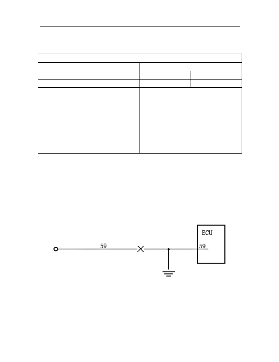
Schematic Circuit: 


Vehicle Speed 

Signal 


-------------------------------------------------------------------------------------------------------------------------------------------------------------

General Precautions of EFI System Maintenance 

F-64 

Malfunction Diagnostic Guide: 

Required  Equipment:  (Diagnostic  Instrument  with  EOBD  Diagnostic  Function,  Digital  Multimeter,  and 
Correct Circuit Diagram) 

Step I: Use diagnostic instrument to read the malfunction information 

Read Result I 

Read Result II 

MIL Lamp On 

P-CODE Present 

MIL Lamp Off 

P-CODE Present 


P0501 


P0501 

Maintenance tips: 

The  malfunction  has  been  confirmed,  and  the 
following problems may possibly exist 

1)  The  circuit  for the Pin 59#  of ECU connected  to 

the  vehicle  speed  signal  sensor  open  circuit  or 
short to ground. 

Maintenance tips: 

The  malfunction  is  not  ultimately  confirmed  and  it 
may  possibly  be  a  random  malfunction.  Inspect  the 
following items:   

1) 

Inspect  the  electric  resistance  of  the  circuit  for 
the  Pin  59#  for  connector  of  ECU  connected  to 
the vehicle speed signal sensor. 

2) 

Inspect the  electric  resistance  for the  Pin 59#  of 
ECU to ground. 


79.  P0506 Idling Speed Control Rotational Speed Higher than Target Idling Speed 

Description about Malfunction Cause: 

The idling rotational speed of electronic throttle is actuated by ECU control DC motor and achieved through 
throttle opening controlled by drive mechanism. If ECU commands the idling speed equals to target value, but 
the actual engine speed  is still lower than the target idling speed  by certain value, it is then determined to be 
the malfunction of small opening jam. 

Malfunction Diagnostic Guide: 

Required Equipment: (Diagnostic Instrument with EOBD Diagnostic Function) 

Step I: Use diagnostic instrument to read the malfunction information 

Read Result I 

Read Result II 

MIL Lamp On 

P-CODE Present 

MIL Lamp Off 

P-CODE Present 


P0506 


P0506 

Maintenance tips: 

The  malfunction  has  been  confirmed,  and  the 
following problems may possibly exist 

1) 

Deviation in processing size for throttle body 

2) 

Inside of throttle body too dirty 

3) 

Stepping motor failed 

Maintenance tips: 

The  malfunction  has  not  been  finally  confirmed,  and 
it is possibly a random malfunction. 


-------------------------------------------------------------------------------------------------------------------------------------------------------------

General Precautions of EFI System Maintenance 

F-65 

80.  P0507 Idling Control Rotational Speed Lower than Target Idling Speed 

Description about Malfunction Cause: 

The idling rotational speed of electronic throttle is actuated by ECU control DC motor and achieved through 
throttle opening controlled by drive mechanism. If ECU commands the idling speed equals to target value, but 
the actual engine speed is still higher than the target idling speed by certain value, it is then determined to be 
the malfunction of large opening jam. 

Malfunction Diagnostic Guide: 

Required Equipment: (Diagnostic Instrument with EOBD Diagnostic Function) 

Step I: Use diagnostic instrument to read the malfunction information 

Read Result I 

Read Result II 

MIL Lamp On 

P-CODE Present 

MIL Lamp Off 

P-CODE Present 


P0507 


P0507 

Maintenance tips: 

The  malfunction  has  been  confirmed,  and  the 
following problems may possibly exist 

1) 

Deviation in processing size for throttle body 

2) 

Inside of throttle body too dirty 

3) 

Stepping motor failed 

Maintenance tips: 

The  malfunction  has  not  been  finally  confirmed,  and 
it is possibly a random malfunction. 


81.  P0508 Stepping Motor Drive Pin Short to Ground (Refer to the figure below) 

P0509 Drive Pin of Stepping Motor Short to Power Supply (Refer to the figure below) 

P0511  Open  Circuit  Connected  with  Stepping  Motor  Drive  Pin  (Refer  to  the  figure 
below) 


-------------------------------------------------------------------------------------------------------------------------------------------------------------

General Precautions of EFI System Maintenance 

F-66 

Step I: Use diagnostic instrument to read the malfunction information 

Read Result I 

Read Result II 

MIL Lamp On 

P-CODE Present 

MIL Lamp Off 

P-CODE Present 


P0508, P0509, P0511 


P0508, P0509, P0511 

Maintenance tips: 

The  malfunction  has  been  confirmed,  and  the 
following problems may possibly exist 

1) Open circuit of Pins 64#, 65#, 66# and 67#; 

2)  Pins  64#,  65#,  66#  and  67#  short  circuited  to 
ground; 

3)  Pins  64#,  65#,  66#  and  67#  short  circuited  to 
power supply 

Maintenance tips: 

The  malfunction  is  not  ultimately  confirmed  and  it 
may  possibly  be  a  random  malfunction.  Inspect  the 
following items:   

1) Harnesses of Pins 64#, 65#, 66# and 67# 


82. P0560 System Battery Voltage Signal Irrational 

Description about Malfunction Cause: 

After  engine  has  been  started,  ECU  performs  continuous  monitoring  over  the  voltage  of  battery,  and  the 
system will determine the voltage of battery to be irrational, when it is found that the battery voltage is always 
lower than 10V. 

Malfunction Diagnostic Guide: 

Required  Equipment:  (Diagnostic  Instrument  with  EOBD  Diagnostic  Function,  Digital  Multimeter,  and 
Correct Circuit Diagram) 


Step I: Use diagnostic instrument to read the malfunction information 

Read Result I 

Read Result II 


P-CODE Present 


P-CODE Present 


P0560 


P0560 

Maintenance tips: 

The  malfunction  has  been  confirmed,  and 
the following problems may possibly exist 

1) 


The  performance  of  power  generator 
reduced  and  generation  capacity 
insufficient. 

Maintenance tips: 

The  malfunction  is  not  ultimately  confirmed  and  it  may 
possibly be a random malfunction. Inspect the following items:   

1) 


Inspect  the  generation  capacity  of  power  generator 
(generation voltage to be measured after engine is started) 


83.  Battery Voltage too Low (Generator without Voltage Output) 

Description about Malfunction Cause: 

After  engine  has  been  started,  ECU  performs  continuous  monitoring  over  the  voltage  of  battery,  and  the 
system  will  determine  that  the  voltage  of  battery  is  too  low,  when  it  is  found  that  the  voltage  of  battery  is 
lower than the system required lower limit. 

Malfunction Diagnostic Guide: 

Required  Equipment:  (Diagnostic  Instrument  with  EOBD  Diagnostic  Function,  Digital  Multimeter,  and 

-------------------------------------------------------------------------------------------------------------------------------------------------------------

General Precautions of EFI System Maintenance 

F-67 

Correct Circuit Diagram) 

Step I: Use diagnostic instrument to read the malfunction information 

Read Result I 

Read Result II 


P-CODE Present 


P-CODE Present 


P0562 


P0562 

Maintenance tips: 

The malfunction has been confirmed, and the 
following problems may possibly exist 

1) 

The  power  generator  already  damaged 
and failed for power generation 

2) 

Generator excitation circuit open 

Maintenance tips: 

The  malfunction  is  not  ultimately  confirmed  and  it  may 
possibly  be  a  random  malfunction.  Inspect  the  following 
items:   

1) 

Inspect  the  generation  capacity  of  power  generator 
(voltage of generator to be measured after startup) 


84.  P0563 System Battery Voltage too High 

Description about Malfunction Cause: 

After  engine  has  been  started,  ECU  performs  continuous  monitoring  over  the  voltage  of  battery,  and  the 
system  will  determine  the  voltage  of  battery  to  be  too  high,  when  if  is  found  that  the  battery  voltage  is  h 
higher than the upper limit set by the system. 

Malfunction Diagnostic Guide: 

Required  Equipment:  (Diagnostic  Instrument  with  EOBD  Diagnostic  Function,  Digital  Multimeter,  and 
Correct Circuit Diagram) 


Step I: Use diagnostic instrument to read the malfunction information 

Read Result I 

Read Result II 


P-CODE Present 


P-CODE Present 


P0563 


P0563 

Maintenance tips: 

The malfunction has been confirmed, and the 
following problems may possibly exist 

1) 

Engine  regulator  already  damaged  and 
failed  to  control  power  generation 
capacity  leading  to  too  high  generation 
voltage 

Maintenance tips: 

The  malfunction  is  not  ultimately  confirmed  and  it  may 
possibly  be  a  random  malfunction.  Inspect  the  following 
items:   

1) 

Inspect  the  generation  voltage  of  power  generator 
(Voltage to be measured after startup) 


-------------------------------------------------------------------------------------------------------------------------------------------------------------

General Precautions of EFI System Maintenance 

F-68 

85.   

P0571 Brake Switch Signal Circuit Malfunction or Nonsynchronous 


Step I: Use diagnostic instrument to read the malfunction information 

Read Result I 

Read Result II 

SVS lamp On 

P-CODE Present 

SVS lamp Off 

P-CODE Present 


P0571 


P0571 

Maintenance tips: 

The  malfunction  has  been  confirmed,  and  the 
following problems may possibly exist 

1)    Brake switch connected to Pin 58# of ECU open 

circuit,  short  circuited  to  ground  or  power 
supply. 

Maintenance tips: 

The  malfunction  is  not  ultimately  confirmed  and  it 
may  possibly  be  a  random  malfunction.  Inspect  the 
following items:   

1)    Check  harness  circuits  of  brake  switch 

connected to Pin 58# of ECU. 


86. P0602 Electronic Control Unit Coding Malfunction   

Step I: Use diagnostic instrument to read the malfunction information 

Read Result I 

Read Result II 

MIL Lamp On 

P-CODE Present 

MIL Lamp Off 

P-CODE Present 


P0602 


P0602 

Maintenance tips: 

The  malfunction  has  been  confirmed,  and  the 
following problems may possibly exist 

1) 


Replace ECU hardware. 

Maintenance tips: 

The  malfunction  is  not  ultimately  confirmed  and  it 
may  possibly  be  a  random  malfunction.  Inspect  the 
following items:   

1) 


Replace  ECU  hardware  and  test  three  driving 
cycle for the problem of ECU. 


Battery 

Ignition switch 

B

ra

k

e s

w

it

ch
 

-------------------------------------------------------------------------------------------------------------------------------------------------------------

General Precautions of EFI System Maintenance 

F-69 

87. P0604 Electronic Control Unit RAM Malfunction   

P0605 Electronic Control Unit ROM Malfunction   

Step I: Use diagnostic instrument to read the malfunction information 

Read Result I 

Read Result II 

MIL Lamp On 

P-CODE Present 

MIL Lamp Off 

P-CODE Present 


P0604, P0605 


P0604, P0605 

Maintenance tips: 

The  malfunction  has  been  confirmed,  and  the 
following problems may possibly exist 

1) 


ECU fails and please replace the ECU. 

Maintenance tips: 

The  malfunction  has  not  been  finally  confirmed,  and 
it is possibly a random malfunction.。 


88. P0606 Electronic Throttle Opening Security Monitoring Malfunction 

Description about Malfunction Cause: 

Air  intake  volume  of  ME7  system  is  controlled  by  electronic  throttle,  and  any  signal  error,  software  or 
hardware  errors shall result in electronic throttle  out of  control, leading to  danger due to sudden acceleration 
of  vehicle.  Spare  parts  and  signals  relevant  to  electronic  throttle  security  monitoring  malfunction  are 
electronic throttle pedal and throttle body, cruise control and brake signals.   

Malfunction Diagnostic Guide: 

Required  Equipment:  (Diagnostic  Instrument  with  EOBD  Diagnostic  Function,  Digital  Multimeter,  and 
Correct Circuit Diagram) 

Step I: Use diagnostic instrument to read the malfunction information 

Read Result I 

Read Result II 


P-CODE Present 


P-CODE Present 


P0606 


P0606 

Maintenance tips: 

The  malfunction  has  been  confirmed,  and  the 
following problems may possibly exist 

1) 


Signal malfunction 

2) 


NLP malfunction 

3) 


SFC malfunction 

4)


ECU hardware malfunction 

Maintenance tips: 

The  malfunction  is  not  ultimately  confirmed  and  it 
may  possibly  be  a  random  malfunction.  Inspect  the 
following items:   

1) 


Please  check  signals  of  electronic  throttle  pedal 
and  throttle  body,  cruise  control  and  brake 
signals.   


89. P0627 

Oil Pump Relay Control Circuit Open


Description about Malfunction Cause: 

After  engine  has  been  started,  the  voltage  of  fuel  pump  relay  circuit  is  to  be  measured  by  the  circuit 
control module inside ECU, and when the voltage complies with the voltage in the mode of open circuit, 
it is determined to be open circuit of fuel pump relay. 

-------------------------------------------------------------------------------------------------------------------------------------------------------------

General Precautions of EFI System Maintenance 

F-70 


Schematic Circuit: 


Malfunction Diagnostic Guide: 

Required  Equipment:  (Diagnostic  Instrument  with  EOBD  Diagnostic  Function,  Digital  Multimeter,  and 
Correct Circuit Diagram) 

Step I: Use diagnostic instrument to read the malfunction information 

Read Result I 

Read Result II 

MIL Lamp On 

P-CODE Present 

MIL Lamp Off 

P-CODE Present 


P0627 


P0627 

Maintenance tips: 

The  malfunction  has  been  confirmed,  and  the 
following problems may possibly exist 

1) 

The circuit connected to Pin 70# of ECU and the 
Pin 85# of relay in open circuit 

2) 

The Pin 86# of relay connected to the main relay 
in open circuit 

3) 

The  electromagnetic  coil  between  Pin  85#  and 
Pin 86# of relay in open circuit 

Maintenance tips: 

The  malfunction  is  not  ultimately  confirmed  and  it 
may  possibly  be  a  random  malfunction.  Inspect  the 
following items:   

1) 

Measure  the  electric  resistance  of  the  line 
between  Pin  70#  for  connector  of  ECU  and  Pin 
85# of relay. 

2) 

The electric resistance for Pin 86# of relay to the 
relay 

3) 

The electric resistance between  Pin 85# and  Pin 
86# of relay 


90. 

P0628 Oil Pump Relay Control Circuit Short to Ground


Description about Malfunction Cause: 

After engine  has been started, the  voltage  of  fuel pump relay circuit is to be  measured  by  the  circuit  control 
module  inside  ECU,  and  when  the  voltage  complies  with  the  voltage  in  the  mode  of  short  to  ground,  it  is 
determined to be fuel pump relay circuit short to ground. 

Schematic Circuit: 

Battery 

Fue

l P

u

m

R

el

ay


Main relay 

Fuel Pump   

-------------------------------------------------------------------------------------------------------------------------------------------------------------

General Precautions of EFI System Maintenance 

F-71 


Malfunction Diagnostic Guide: 

Required  Equipment:  (Diagnostic  Instrument  with  EOBD  Diagnostic  Function,  Digital  Multimeter,  and 
Correct Circuit Diagram) 

Step I: Use diagnostic instrument to read the malfunction information 

Read Result I 

Read Result II 

MIL Lamp On 

P-CODE Present 

MIL Lamp Off 

P-CODE Present 


P0628 


P0628 

Maintenance tips: 

The  malfunction  has  been  confirmed,  and  the 
following problems may possibly exist 

1) 

The  circuit  connected  to  Pin  70#  of  ECU  short 
to ground 

Maintenance tips: 

The  malfunction  is  not  ultimately  confirmed  and  it 
may  possibly  be  a  random  malfunction.  Inspect  the 
following items:   

1) 

Measure  whether  or  not  the  electric  resistance 
for  Pin  70#  of  ECU  to  ground  is  under  normal 
condition 

91. 

P0629 Oil Pump Relay Control Circuit Short to Power Supply


Description about Malfunction Cause: 

After engine  has been started, the  voltage  of  fuel pump relay circuit is to be  measured  by  the  circuit  control 
module inside ECU, and when the voltage complies with the voltage in the mode of short to power supply, it 
is determined to be fuel pump relay circuit short to power supply. 

Schematic Circuit: 


Battery 

Main relay 

F

u

el P

u

m

R

el

ay


Fuel Pump   

Battery 

Main relay 

F

uel P

u

m

R

el

ay


Fuel Pump   

-------------------------------------------------------------------------------------------------------------------------------------------------------------

General Precautions of EFI System Maintenance 

F-72 

Step I: Use diagnostic instrument to read the malfunction information 

Read Result I 

Read Result II 

MIL Lamp On 

P-CODE Present 

MIL Lamp Off 

P-CODE Present 


P0629 


P0629 

Maintenance tips: 

The  malfunction  has  been  confirmed,  and  the 
following problems may possibly exist 

1) 

The circuit connected to Pin 70# of ECU and the 
circuit  of  Pin  30#  for  fuel  pump  relay  in  short 
circuit 

2) 

The circuit connected to Pin 70# of ECU and the 
circuit  of  Pin  86#  for  fuel  pump  relay  in  short 
circuit 

3) 

The  circuit  connected  to  Pin  70#  of  ECU  and 
other power supply circuit in short circuit   

Maintenance tips: 

The  malfunction  is  not  ultimately  confirmed  and  it 
may  possibly  be  a  random  malfunction.  Inspect  the 
following items:   

1) 

Measure  whether  or  not  the  voltage  for  Pin  70# 
of ECU is under normal condition 

2) 

Measure the electric resistance between Pin 70# 
of ECU and Pins 30# and 86# of Relay 


92. 

P0645 Control Circuit of A/C Compressor Relay in Open Circuit


Description about Malfunction Cause: 

After  engine  has  been  started,  circuit  control  module  of  ECU  examines  voltage  of  A/C  compressor  relay 
control  circuit.  If  open  mode  value  is  detected,  malfunction  of  open  A/C  compressor  relay  control  circuit  is 
indicated. 

Schematic Circuit: 


Malfunction Diagnostic Guide: 

Required  Equipment:  (Diagnostic  Instrument  with  EOBD  Diagnostic  Function,  Digital  Multimeter,  and 
Correct Circuit Diagram) 


Battery 

Main relay 

A

/C
 C

o

m

p

re

ss

or


R

el

ay


-------------------------------------------------------------------------------------------------------------------------------------------------------------

General Precautions of EFI System Maintenance 

F-73 

Step I: Use diagnostic instrument to read the malfunction information 

Read Result I 

Read Result II 

SVS lamp On 

P-CODE Present 

SVS lamp Off 

P-CODE Present 


P0645 


P0645 

Maintenance tips: 

The  malfunction  has  been  confirmed,  and  the 
following problems may possibly exist 

1)    Circuit  between  ECU  Pin  69#  and  A/C 

compressor relay Pin 85# is open. 

2)    Circuit  between  A/C  compressor  relay  Pin  30# 

and main relay is open. 

3)    Circuit  between  A/C  compressor  relay  Pin  87# 

and battery is open. 

Maintenance tips: 

The  malfunction  is  not  ultimately  confirmed  and  it 
may  possibly  be  a  random  malfunction.  Inspect  the 
following items:   

1)    Examine  resistance  of  circuit  between  Pin  69# 

of ECU connector and A/C compressor relay Pin 
85#.   

2)    Examine  resistance  of  circuit  between  A/C 

compressor relay Pin 30# and main relay. 

3)    Examine  resistance  of  circuit  between  A/C 

compressor relay Pin 87# and battery. 


93. P0646 Control Circuit of A/C Compressor Relay Short to Ground 

Description about Malfunction Cause: 

After engine  has been started, the voltage  of relay  circuit is to  be  measured by  circuit control  module inside 
ECU, and  when the  voltage complies with the voltage in the  mode  of short to  ground, it  is  determined to  be 
the malfunction of circuit short to ground. 

Schematic Circuit: 


Battery 

Main relay 

A

/C
 C

o

m

p

re

ss

or

 R

el

ay


-------------------------------------------------------------------------------------------------------------------------------------------------------------

General Precautions of EFI System Maintenance 

F-74 

Malfunction Diagnostic Guide: 

Required  Equipment:  (Diagnostic  Instrument  with  EOBD  Diagnostic  Function,  Digital  Multimeter,  and 
Correct Circuit Diagram) 

Step I: Use diagnostic instrument to read the malfunction information 

Read Result I 

Read Result II 

SVS lamp On 

P-CODE Present 

SVS lamp Off 

P-CODE Present 


P0646 


P0646 

Maintenance tips: 

The  malfunction  has  been  confirmed,  and  the 
following problems may possibly exist 

1) 

The  circuit  connected  to  Pin  69#  of  ECU  short 
to ground 

Maintenance tips: 

The  malfunction  is  not  ultimately  confirmed  and  it 
may  possibly  be  a  random  malfunction.  Inspect  the 
following items:   

1) 

Whether  or  not  the  resistance  for  Pin  69#  of 
ECU to Ground is under normal condition 


94. P0647 Control Circuit of A/C Compressor Relay Short to Power Supply 

Description about Malfunction Cause: 

After engine  has been started, the voltage  of relay  circuit is to  be  measured by  circuit control  module inside 
ECU, and when the voltage complies with the voltage in the mode of short to power supply, it is determined to 
be the malfunction of short to power supply. 

Schematic Circuit: 


Battery 

Main relay 

A

/C
 C

o

m

p

re

ss

or

 R

el

ay


-------------------------------------------------------------------------------------------------------------------------------------------------------------

General Precautions of EFI System Maintenance 

F-75 

Malfunction Diagnostic Guide: 

Required  Equipment:  (Diagnostic  Instrument  with  EOBD  Diagnostic  Function,  Digital  Multimeter,  and 
Correct Circuit Diagram) 

Step I: Use diagnostic instrument to read the malfunction information 

Read Result I 

Read Result II 

SVS lamp On 

P-CODE Present 

SVS lamp Off 

P-CODE Present 


P0647 


P0647 

Maintenance tips: 

The  malfunction  has  been  confirmed,  and  the 
following problems may possibly exist 

1) 

The circuit connected to Pin 69# of ECU and the 
circuit  of  Pin  86#  of  air  conditioning  relay 
connected  to  the  main  relay  of  power  supply  in 
short circuit 

2) 

The circuit connected to Pin 69# of ECU and the 
circuit  of  Pin  30#  of  air  conditioning  relay 
connected to the positive pole of battery in short 
circuit 

3) 

The  circuit  connected  to  Pin  69#  of  ECU  and 
other power supply circuit in short circuit 

Maintenance tips: 

The  malfunction  is  not  ultimately  confirmed  and  it 
may  possibly  be  a  random  malfunction.  Inspect  the 
following items:   

1)    Resistance  of  between  circuit  connected  with 

ECU Pin 69# and circuit between A/C relay  Pin 
86# and power supply main relay. 

2)    Resistance  of  circuit  between  ECU  69#  and 

positive battery pole. 

3)    Resistance  of  between  circuit  connected  with 

ECU Pin 69# and other power circuit. 


95. P0650 Malfunction Indicator Lamp (MIL) Circuit Malfunction 

Description about Malfunction Cause: 

The  voltage  of  malfunction  indicator  lamp  circuit  is  to  be  measured  by  the  control  module  for  malfunction 
indicator  lamp  circuit  inside  ECU,  and  when  the  voltage  complies  with  the  voltage  in  the  mode  of  circuit 
malfunction, it is determined to be a malfunction of malfunction indicator lamp circuit. 

Schematic Circuit:


Ignition switch 

-------------------------------------------------------------------------------------------------------------------------------------------------------------

General Precautions of EFI System Maintenance 

F-76 

Malfunction Diagnostic Guide: 

Required  Equipment:  (Diagnostic  Instrument  with  EOBD  Diagnostic  Function,  Digital  Multimeter,  and 
Correct Circuit Diagram) 

Step I: Use diagnostic instrument to read the malfunction information 

Read Result I 

Read Result II 

1. MIL Lamp On 

2. MIL Off 

P-CODE Present 

Malfunction Lamp Off 

P-CODE Present 


P0650 


P0650 

Maintenance tips: 

The  malfunction  has  been confirmed,  and the 
following problems may possibly exist 

1) 

The circuit connected to Pin 31# of ECU 
in open circuit 

2) 

The circuit connected to Pin 31# of ECU 
short to ground 

3) 

The circuit connected to Pin 31# of ECU 
short to power supply(MIL lamp ON) 

Maintenance tips: 

The  malfunction  is  not  ultimately  confirmed  and  it  may 
possibly  be  a  random  malfunction.  Inspect  the  following 
items:   

1) 

Measure  the  electric  resistance  between  the  line  of  the 
Pin  31#  for  connector  of  ECU  and  the  malfunction 
indicator lamp. 

2) 

Measure the electric resistance between the  Pin 31#  for 
connector of ECU and the ground. 

3) 

Measure the  electric resistance between the  Pin 31#  for 
connector of ECU and the ignition switch 


96. P0688 Improper Output Voltage of Main Relay   

Description about Malfunction Cause: 

After  the  ignition  switch  is  turned  on,  ECU  internal  control  module  performs  measurement  over  output 
voltage  of  main  relay, and if the  measured  voltage exceeds the reasonable  voltage  range preset in ECU, it is 
determined  to be the  malfunction  of improper voltage. Under such circumstance,  neither MIL lamp nor SVS 
lamp will be on. 

97. 

P0691 Control circuit of cooling fan relay short to ground (low speed)


Description about Malfunction Cause: 

After  engine  has  been  started,  circuit  control  module  of  ECU  examines  voltage  of  cooling  fan;  if  grounded 
mode value detected, it is determined to be the malfunction of circuit of fan short to ground. 

Schematic Circuit: 


Battery 

Main relay 

-------------------------------------------------------------------------------------------------------------------------------------------------------------

General Precautions of EFI System Maintenance 

F-77 

Malfunction Diagnostic Guide: 

Required  Equipment:  (Diagnostic  Instrument  with  EOBD  Diagnostic  Function,  Digital  Multimeter,  and 
Correct Circuit Diagram) 

Step I: Use diagnostic instrument to read the malfunction information 

Read Result I 

Read Result II 

SVS lamp On 

P-CODE Present 

SVS lamp Off 

P-CODE Present 


P0691 


P0691 

Maintenance tips: 

The  malfunction  has  been  confirmed,  and  the 
following problems may possibly exist 

1)    Circuit  between  ECU  Pin  50#  and  cooling  fan 

relay Pin 85# short to ground 

Maintenance tips: 

The  malfunction  is  not  ultimately  confirmed  and  it 
may  possibly  be  a  random  malfunction.  Inspect  the 
following items:   

1)    Examine resistance of circuit between Pin 50# of 

ECU  and  cooling  fan  relay  Pin  85#  short  to 
ground 


98. P0692 Control Circuit of Cooling Fan Relay Short to Power Supply (Low Speed) 

Description about Malfunction Cause: 

After  engine  has  been  started,  circuit  control  module  of  ECU  examines  voltage  of  cooling  fan  circuit;  if  the 
value  complies  with  the  voltage  in  the  short-with-power  mode,  it  is  determined  to  be  the  malfunction  of 
cooling fan circuit short to power supply. 

Schematic Circuit: 


Malfunction Diagnostic Guide: 

Required  Equipment:  (Diagnostic  Instrument  with  EOBD  Diagnostic  Function,  Digital  Multimeter,  and 
Correct Circuit Diagram) 


Battery 

Main relay 

-------------------------------------------------------------------------------------------------------------------------------------------------------------

General Precautions of EFI System Maintenance 

F-78 

Step I: Use diagnostic instrument to read the malfunction information 

Read Result I 

Read Result II 

SVS lamp On 

P-CODE Present 

SVS lamp Off 

P-CODE Present 


P0692 


P0692 

Maintenance tips: 

The  malfunction  has  been  confirmed,  and  the 
following problems may possibly exist 

1)    Circuit  connected  with  ECU  Pin  50#  short  to 

circuit  between  cooling  fan  relay  Pin  86#  and 
main relay. 

2)    Circuit  connected  with  ECU  Pin  50#  short  to 

circuit  between  cooling  fan  relay  Pin  30#  and 
positive battery pole. 

3)    Circuit  connected  with  ECU  50#  short  to  other 

power circuit. 

Maintenance tips: 

The  malfunction  is  not  ultimately  confirmed  and  it 
may  possibly  be  a  random  malfunction.  Inspect  the 
following items:   

1) 

Examine  resistance  between  circuit  connected 
with  ECU  Pin  50#  and  circuit  between  cooling 
fan relay Pin 86# and main relay. 

2)    Examine  resistance  between  circuit  connected 

with  ECU  Pin  50#  and  circuit  between  cooling 
fan relay Pin 86# and positive battery pole. 

3) 

Examine  resistance  between  circuit  connected 
with ECU Pin 68# and other power circuit. 


99.  P0693 Control Circuit of Cooling Fan Relay Short to Ground (High Speed) 

Description about Malfunction Cause: 

After  engine  has  been  started,  circuit  control  module  of  ECU  examines  voltage  of  cooling  fan  circuit;  if  the 
value complies with the voltage in the mode of circuit short to ground, it is determined to be the malfunction 
of cooling fan circuit short to ground. 

Schematic Circuit: 


Malfunction Diagnostic Guide: 

Required  Equipment:  (Diagnostic  Instrument  with  EOBD  Diagnostic  Function,  Digital  Multimeter,  and 
Correct Circuit Diagram) 

Step I: Use diagnostic instrument to read the malfunction information 

Read Result I 

Read Result II 

SVS lamp On 

P-CODE Present 

SVS lamp Off 

P-CODE Present 


P0693 


P0693 

Battery 

Main relay 

-------------------------------------------------------------------------------------------------------------------------------------------------------------


Content      ..     3      4      5      6     ..