Haima 7. Air-intake System. Service Manual - part 2
General Precautions of EFI System Maintenance
F-17
16. P0054 Downstream Oxygen Sensor Internal Resistance Irrational
Description about Malfunction Cause:
Heater of oxygen sensor is diagnosed through monitoring over the internal resistance of heater. The internal
resistance of heater is determined by temperature of ceramic, while the temperature of ceramic is subjected to
the impact of waste gas temperature in the heater and the catalyst converter. The diagnosis is performed
through comparison between the measurement value and the reference value (related to heater efficiency and
the temperature in catalyst converter) for the internal resistance of ceramic. It will be determined to be heating
malfunction if the measurement value exceeds the reference value or malfunction exists with the heater at
power level.
Malfunction Diagnostic Guide:
Required Equipment: (Diagnostic Instrument with EOBD Diagnostic Function)
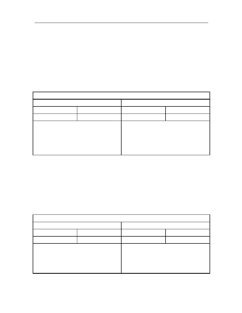
Step I: Use diagnostic instrument to read the malfunction information
Read Result I
Read Result II
MIL Lamp On
P-CODE Present
MIL Lamp Off
P-CODE Present
P0054
P0054
Maintenance tips:
The malfunction has been confirmed, and the
following problems may possibly exist
1) The heating function of downstream oxygen
sensor failed, and the oxygen sensor to be
replaced.
Maintenance tips:
The malfunction has not been finally confirmed.
Please wait for system to fulfill diagnosis.。
17. P0101 Air Flow Meter Sensor Signal Irrational
Description about Malfunction Cause:
The signal of air flow meter sensor is obtained by the transformation of temperature difference signal to
voltage signal. After the start of engine, if through comparison of the continuously checked voltage signal of
air flow meter sensor with the theoretical value stored in ECU, the voltage signal is not within the theoretical
value range, signal irrational is determined by the diagnostic system.
Malfunction Diagnostic Guide:
Required Equipment: (Diagnostic Instrument with EOBD Diagnostic Function)
Step I: Use diagnostic instrument to read the malfunction information
Read Result I
Read Result II
MIL Lamp On
P-CODE Present
MIL Lamp Off
P-CODE Present
P0054
P0054
Maintenance tips:
The malfunction has been confirmed, and the
following problems may possibly exist
The air flow meter failed, and the air flow meter to be
replaced
Maintenance tips:
The malfunction has not been finally confirmed.
Please wait for system to fulfill diagnosis.。