Rover 214-414. Service Repair Manual - part 11
 

  Index      Manuals     Rover 214-414. Service Repair Manual


Search            copyright infringement  


Content      ..     9      10      11      12     ..


Rover 214-414. Service Repair Manual - part 11


knurled wheel are situated on the underside of
the strut assembly. Using a screwdriver, move
the quadrant away from the knurled wheel
and set it in the minimum adjustment position.
12 Fit the upper return spring to its
respective location on the leading shoe. Fit
the trailing shoe to the upper return spring
and carefully ease the shoe into position in the
adjuster strut slot. Once in position, fit the
small spring which secures the trailing shoe to
the strut assembly.
13 Remove the elastic band fitted to the wheel
cylinder and manoeuvre the shoe and strut
assembly into position on the backplate.
Locate the upper end of both shoes with the
wheel cylinder pistons and fit the handbrake
cable to the trailing shoe operating lever. Fit the
lower return spring to both shoes and ease the
shoes into position on the lower pivot point.
14 Tap the shoes to centralise them with the
backplate, then refit the shoe retainer pins
and springs and secure them in position with
the retainer clips. Check that the adjuster
quadrant is still in the minimum adjuster
position and if necessary, reset as follows.
Place a block of wood between the trailing
shoe and hub, to prevent the shoe moving
forwards, then lever the leading shoe away
from the hub to release the brake shoe return
spring pressure on the adjuster quadrant.
With the shoe held in this position, reset the
quadrant to the minimum adjustment setting
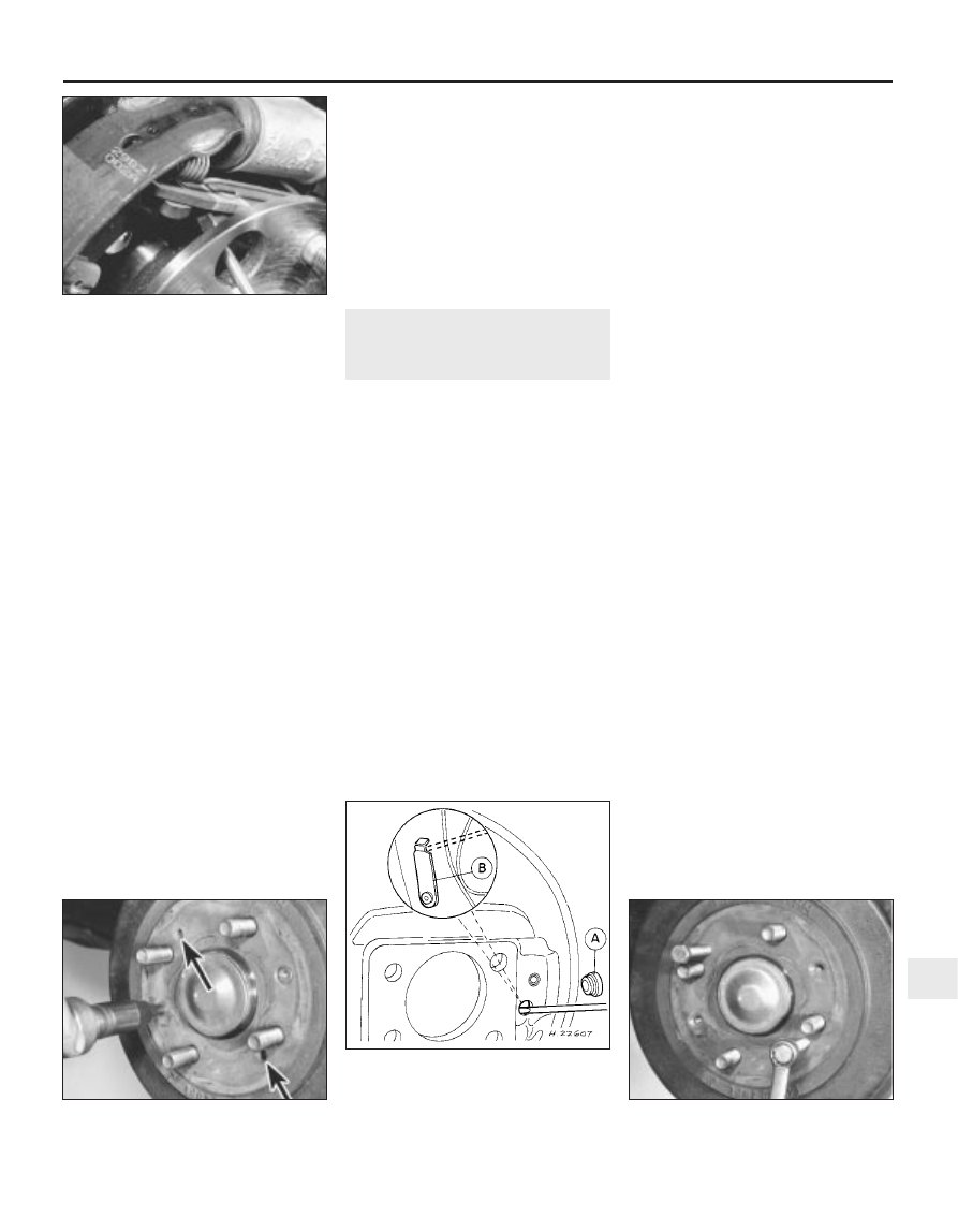
(see illustration). Once the adjuster strut is
correctly set, ease the leading shoe back into
position then remove the block of wood and
check that the shoes are still central.

15 Refit the brake drum and repeat the above
operation on the remaining rear brake
assembly.
16 On completion, apply the footbrake
repeatedly to set the shoe-to-drum clearance,
until normal (non-assisted) brake pedal
operation returns.
17 Check handbrake cable operation and, if
necessary, adjust as described in Chapter 1.
18 Refit the roadwheels then lower the
vehicle to the ground and tighten the
roadwheel nuts to the specified torque.
19 Check the hydraulic fluid level.

17 Rear brake drum - removal,

inspection and refitting

2

Note: If either brake drum requires renewal,
both should be renewed at the same time to
ensure even and consistent braking.

Removal

Chock the front wheels then jack up the
rear of the vehicle and support it on axle
stands. Remove the appropriate rear wheel.
Use chalk or paint to mark the relationship
of the drum to the hub.
With the handbrake firmly applied to
prevent drum rotation, unscrew the drum
retaining screws (see illustration). Fully
release the handbrake cable and withdraw the
drum.
If the drum will not pull away, first check
that the handbrake is fully released. If the
drum will still not come away, remove the
grommet from the rear of the backplate and,
using a small screwdriver, disengage the
handbrake lever stop from behind the lever to
increase the shoe to drum clearance. If
removal still proves troublesome, the brake
drum can be drawn off by screwing two bolts
into the jacking holes provided (see
illustrations)
.

Inspection

Working carefully, remove all traces of
brake dust from the drum. Avoid inhaling the
dust as it is injurious to health.
Scrub clean the outside of the drum 
and check it for obvious signs of wear or
damage such as cracks around the road-
wheel stud holes. Renew the drum if
necessary.
Examine carefully the inside of the drum.
Light scoring of the friction surface is normal
but if heavy scoring is found, the drum must
be renewed. It is usual to find a lip on the
drum’s inboard edge which consists of a
mixture of rust and brake dust. This should be
scraped away to leave a smooth surface
which can be polished with fine (120 to 150
grade) emery paper. If, however, the lip is due
to the friction surface being recessed by
excessive wear, then the drum must be
renewed.
If the drum is thought to be excessively
worn or oval, its internal diameter must be
measured at several points by using an
internal micrometer. Take measurements in
pairs, the second at right angles to the first,
and compare the two to check for signs of
ovality. Provided that it does not enlarge the
drum to beyond the specified maximum
diameter, it may be possible to have the drum
refinished by skimming or grinding but if this
is not possible, the drums on both sides must
be renewed
.

Refitting

Refitting is the reverse of the removal
procedure, noting the following:
a)

On fitting a new brake drum, use a
suitable solvent to remove any
preservative coating that may have been
applied to its interior.

b)

Use a clean wire brush to remove all
traces of dirt, brake dust and corrosion
from the mating surfaces of the drum and
the hub flange.

c)

Align (if applicable) the marks made on
removal.

d)

Tighten the drum retaining screws and the
roadwheel nuts to their specified torque
wrench settings.

Braking system  9•13

16.14  Reset adjuster strut prior to refitting

drum

17.4b  Brake drum can be drawn off hub by

using two 8 mm bolts

17.4a  Releasing handbrake mechanism

stop lever

Remove rubber grommet (A) and use small

screwdriver to depress handbrake lever 

stop (B)

17.3  Removing brake drum retaining

screws (jacking holes arrowed)

9

1689 Rover 214 & 414 Updated Version 09/97

-------------------------------------------------------------------------------------------------------------------------------------------------------------

18 Rear wheel cylinder -

removal, overhaul and refitting

4

Note: Before attempting to overhaul a rear
wheel cylinder, check the price and availability
of individual components and the price of a
new or reconditioned unit, as overhaul may
not be viable on economic grounds alone.

Removal

Remove the brake shoes.
Minimise fluid loss by removing the master
cylinder reservoir cap and then tightening it
down onto a piece of polythene to obtain an
airtight seal (taking care not to damage the
sender unit), or by using a brake hose clamp,
a G-clamp or a similar tool to clamp the
flexible hose.
Wipe away all traces of dirt around the
brake pipe union at the rear of the wheel
cylinder and unscrew the union nut. Carefully
ease the pipe out of the wheel cylinder and
plug or tape over its end to prevent dirt entry
(see illustration).
Unscrew the two wheel cylinder retaining
bolts from the rear of the backplate and
remove the cylinder, noting the rubber sealing
ring which is fitted between the cylinder and
backplate.

Overhaul

Remove the wheel cylinder from the vehicle
and clean it thoroughly.
Mount the wheel cylinder in a soft-jawed
vice and remove the rubber protective caps.
Extract the piston assemblies.
Thoroughly clean all components using
only methylated spirit, isopropyl alcohol or
clean hydraulic fluid as a cleaning medium.
Never use mineral-based solvents such as
petrol or paraffin which will attack the
hydraulic system’s rubber components. Dry
the components immediately using
compressed air or a clean, lint-free cloth.
Check all components and renew any that
are worn or damaged. Check particularly the
cylinder bore and pistons. The complete
assembly must be renewed if these are

scratched, worn or corroded. If there is any
doubt about the condition of the assembly or
of any of its components, renew it. Remove
the bleed screw and check that the fluid entry
port and bleed screw passages are clear.
If the assembly is fit for further use, obtain a
repair kit. Renew the rubber protective caps,
dust caps and seals disturbed on dismantling,
these should never be re-used. Renew also
any other items included in the repair kit.
10 On reassembly, soak the pistons and the
new seals in clean hydraulic fluid. Smear
clean fluid on the cylinder bore surface.
11 Fit the new seals to their pistons using
only the fingers to manipulate them into the
grooves. Ensure that all components are
refitted in the correct order and the right way
round.
12 Insert the pistons into the bore using a
twisting motion to avoid trapping the seal lips.
Apply a smear of rubber lubricant to each
piston before fitting the new rubber protective
caps.

Refitting

13 Fit a new sealing ring to the rear of the
wheel cylinder and place the cylinder in
position on the backplate.
14 Refit the wheel cylinder retaining bolts
and tighten them to the specified torque.
15 Tighten the brake pipe union nut and, if
necessary, remove the clamp from the brake
hose.
16 Refit the brake shoes.
17 Bleed the hydraulic braking system. If
precautions were taken to minimise fluid loss,
it should only be necessary to bleed the
relevant rear brake. On completion, check
that both footbrake and handbrake function
correctly before taking the vehicle on the
road.

19 Rear brake pads 

inspection

Refer to Chapter 1.

20 Rear brake pads -

renewal

2

Warning: Renew both sets of
rear brake pads at the same
time. Never renew the pads on

only one wheel as uneven braking may
result.

Removal

Chock the front wheels then jack up the
rear of the vehicle and support on axle stands.
Remove the rear roadwheels.
Undo the two bolts securing the caliper
shield in position and remove the shield from
the rear of the caliper.
Remove both caliper guide pin bolts whilst,

if necessary, using a slim open-ended
spanner to prevent the guide pins from
rotating. Lift the caliper away from the disc,
noting the upper pad spring which is fitted to
the roof of the caliper. Tie the caliper to the
suspension strut using a piece of wire to avoid
straining the hydraulic hose (see illustration).
Remove the brake pads from the caliper
mounting bracket whilst noting the correct
fitted positions of the brake pads, pad retainer
springs and pad shims.
Inspect the pads as described for the front
brake pads and, if necessary, renew as a
complete axle set.

Fitting

Fit the pad retainer springs to the caliper
mounting bracket.
Apply a thin smear of Molykote M77
compound to the sides and back of each
pad’s metal backing and to those surfaces of
the caliper body and mounting bracket which
bear on the pads. In the absence of the
specified lubricant, a good quality high-
temperature brake grease (silicone- or
PBC/Poly Butyl Cuprysil-based) or anti-seize
compound (eg Holts Copaslip) may be used.
Fit the shims to the back of both pads, noting
that the smaller shim must be fitted to the
piston side pad, and apply a thin smear of
lubricant to the back of each shim. Do not
allow lubricant to foul the friction material.
Install the brake pads in the caliper
mounting bracket, ensuring that the friction
material is against the disc and the pad with
the smaller shim attached is fitted on the
inside.
If new pads have been fitted, it will be
necessary to retract the piston fully into the
caliper bore by rotating it in a clockwise
direction. This can be achieved by using a
suitable pair of circlip pliers as a peg spanner
or by fabricating a peg spanner for the task.
Provided that the master cylinder reservoir
has not been overfilled with hydraulic fluid,
there should be no spillage, but keep a careful
watch on the fluid level while retracting the
piston. If the fluid level rises above the MAX
level line at any time, the surplus should be
syphoned off or ejected via a plastic tube
connected to the bleed screw.
10 Ensure the upper pad spring is still in
position in the caliper then slide the caliper
into position in its mounting bracket. When
fitting the caliper, ensure that the lug on the
rear of the piston side pad is located in one of
the piston slots. Refit the caliper guide pin
bolts and tighten them to the specified torque
setting.
11 Depress the footbrake to bring the piston
into contact with the pads then check that the
lug on the piston side pad is located in one of
the piston slots. If necessary, remove the
caliper and adjust the piston position as
described above. Refit the shield to the rear of
the caliper.
12 Repeat the above procedure on the
remaining rear brake caliper.

9•14 Braking system

18.3  Wheel cylinder retaining bolts (A) and

brake pipe union nut (B)

1689 Rover 214 & 414 Updated Version 09/97

-------------------------------------------------------------------------------------------------------------------------------------------------------------

13 Once both calipers have been done,
repeatedly depress the brake pedal until
normal (non-assisted) pedal operation returns,
then repeatedly apply the handbrake to set
handbrake adjustment. Check the operation
of the handbrake and, if necessary, adjust the
cable as described in Chapter 1.
14 Refit the roadwheels, then lower the
vehicle to the ground and tighten the
roadwheel nuts to the specified torque.
15 Check the hydraulic fluid level.

21 Rear brake caliper 

removal, overhaul and refitting

4

Removal

Chock the front wheels, then jack up the
rear of the vehicle and support on axle stands.
Remove the rear wheel.
Undo the two bolts securing the caliper

shield in position and remove the shield from
the rear of the caliper.
Extract the spring clip and clevis pin
securing the handbrake cable to the caliper
handbrake lever, then remove the clip
securing the outer cable to its mounting
bracket and detach the handbrake cable from
the caliper.
Minimise fluid loss by removing the master
cylinder reservoir cap and then tightening it
down onto a piece of polythene to obtain an
airtight seal (taking care not to damage the
sender unit), or by using a brake hose clamp,
a G-clamp or a similar tool to clamp the
flexible hose.
Clean the area around the hose union, then
undo the brake hose union bolt and
disconnect the hose from the caliper. Plug the
end of the hose and the caliper orifice to
prevent dirt entering the hydraulic system.
Discard the sealing washers as they must be
renewed whenever disturbed.
Remove both the caliper guide pin bolts
whilst, if necessary, using a slim open-ended
spanner to prevent the guide pins from
rotating, then lift the caliper away from the
disc, noting the upper pad spring which is
fitted to the roof of the caliper. Note that the
brake pads need not be disturbed and can 
be left in position in the caliper mounting
bracket.

Overhaul

With the caliper on the bench, wipe away all
traces of dust and dirt. Avoid inhaling the dust
as it is injurious to health.
Using a small screwdriver, carefully prise
out the dust seal from the caliper bore.
Remove the piston from the caliper bore by
rotating it in an anti-clockwise direction. This
can be achieved using a suitable pair of circlip
pliers as a peg spanner or by fabricating a peg
spanner for the task. Once the piston turns
freely but does not come out any further, then
it can be withdrawn by hand, or if necessary,
pushed out by applying compressed air to the
union bolt hole. Only low pressure should be
required such as is generated by a foot pump.
10 With the piston removed, extract the
circlip from inside the piston and withdraw the
thrustwasher, spring and adjuster nut.
11 Remove the piston (fluid) seal whilst
taking great care not to scratch the caliper
bore.
12 Extract the circlip from the caliper bore
and withdraw the spring cover, spring, spring
seat, bearing and adjusting bolt. Then remove
the adjusting bolt piston, noting the O-ring
fitted to the rear of the piston, and withdraw
the small pushrod.
13 Slacken and remove the handbrake lever
retaining nut and washer and remove the
return spring, lever and dust seal. Withdraw
the handbrake mechanism cam from the
caliper and remove the cam washer.
14 Withdraw the guide pins from the caliper
mounting bracket and remove the guide pin
gaiters.

Braking system  9•15

9

1689 Rover 214 & 414 Updated Version 09/97

20.3  Rear brake caliper components

1

Handbrake lever retaining
nut

2

Washer

3

Return spring

4

Handbrake operating lever

5

Dust seal

6

Guide pin bolt

7

Caliper body

8

Bleed screw

9

Pushrod

10 O-ring
11 Adjusting bolt piston
12 Adjusting bolt

13 Bearing
14 Spring seat
15 Spring
16 Spring cover
17 Circlip
18 Piston seal
19 Circlip
20 Thrustwasher
21 Spring
22 Adjuster nut
23 Piston
24 Dust seal
25 Pad spring

26 Inner pad shim
27 Brake pads
28 Outer pad shim
29 Pad spring
30 Caliper mounting bracket
31 Gaiter
32 Guide pin
33 Handbrake cable

mounting bracket

34 Cam washer
35 Pin
36 Bolt
37 Handbrake mechanism cam

-------------------------------------------------------------------------------------------------------------------------------------------------------------

15 Inspect all the caliper components as
described for the front brake caliper and
renew as necessary.
16 On reassembly ensure that all
components are absolutely clean and dry.
17 Apply a good quality high-temperature
brake grease (silicone- or PBC/Poly Butyl
Cuprysil-based) or anti-seize compound (eg
Holts Copaslip) to the handbrake mechanism
cam and refit the cam washer and cam to the
caliper. Fit the dust seal, lever, return spring
and washer and tighten the handbrake lever
retaining nut securely.
18 Fit a new O-ring to the adjusting bolt
piston then insert the small pushrod into the
rear of the piston and install the adjusting bolt
piston assembly in the caliper bore. Operate
the handbrake lever and check that the piston
is free to move smoothly then refit the
adjusting bolt, followed by the bearing and
spring seat. Fit the spring, so that its tapered
end is innermost, then install the spring cover.
Secure all the above components in position
with the circlip, ensuring that it is correctly
seated in the groove in the caliper bore.
19 Locate the adjusting nut with the cutout
on the inside of the caliper piston and refit the
spring, thrustwasher and circlip. Ensure the
circlip is correctly located in its groove.
20 Soak the piston and the new piston (fluid)
seal in clean hydraulic fluid. Smear clean fluid
on the cylinder bore surface.
21 Fit the new piston (fluid) seal using only
the fingers to manipulate it into the cylinder
bore groove and refit the piston assembly.
Turn the piston in a clockwise direction, using
the method employed on dismantling, until it
is fully retracted into the caliper bore.
22 Fit the dust seal to the caliper ensuring
that it is correctly located in the caliper and
also the groove on the piston.
23 Apply the grease supplied in the repair kit,
or a good quality high-temperature brake
grease (silicone- or PBC/Poly Butyl Cuprysil-
based) or anti-seize compound (eg Holts
Copaslip), to the guide pins and fit the new
gaiters. Fit the guide pins to the caliper
mounting bracket, ensuring that the gaiters
are correctly located in the grooves on both
the guide pin and mounting bracket.

Refitting

24 Ensure the upper pad spring is still in
position in the caliper then slide the caliper
into position in its mounting bracket. When
fitting the caliper, ensure that the lug on the
rear of the piston side pad is located in the
centre of the caliper piston at the point where
the two piston slots cross. Refit the caliper
guide pin bolts and tighten them to the
specified torque setting.
25 Position a new sealing washer on each
side of the hose union and refit the brake hose
union bolt. Ensure that the brake hose union is
correctly positioned between the lugs on the
caliper then tighten the union bolt to the
specified torque setting.
26 Remove the brake hose clamp, where

fitted, and bleed the hydraulic system.
Providing the precautions described were
taken to minimise brake fluid loss, it should
only be necessary to bleed the relevant rear
brake.
27 Refit the handbrake cable outer to its
mounting bracket and secure it in position
with the retaining clip. Ensure the return
spring is located in the groove in the operating
lever then refit the handbrake cable to lever
clevis pin and secure it in position with the
spring clip.
28 Depress the brake pedal several times
until normal (non-assisted) operation returns
then check and, if necessary, adjust the
handbrake cable as described in Chapter 1.
29 Refit the shield to the rear of the caliper
and tighten its retaining bolts securely.
30 Refit the roadwheel, then lower the
vehicle to the ground and tighten the
roadwheel nuts to the specified torque.
31 Check the hydraulic fluid level.

22 Rear brake disc - inspection,

removal and refitting

3

Note: If either rear brake disc requires
renewal, both should be renewed at the same
time to ensure even and consistent braking.

Inspection

Chock the front wheels, then jack up the
rear of the vehicle and support on axle stands.
Remove the appropriate rear roadwheel.
Inspect the disc as described for the front
brake disc.

Removal

Undo the two caliper shield retaining bolts
and remove the shield from the rear of the
caliper.
Undo the two bolts securing the caliper
mounting bracket to the trailing arm assembly
and slide the caliper assembly off the disc.
Using a piece of wire or string, tie the caliper
to the rear suspension coil spring to avoid
placing any strain on the hydraulic brake
hose.
Use chalk or paint to mark the relationship
of the disc to the hub, then remove the two
screws securing the brake disc to the hub and
remove the disc. If the disc is a tight fit on the
hub, it can be drawn off by screwing two bolts
into the jacking holes provided.

Refitting

Refitting is the reverse of the removal
procedure, noting the following:
a)

Ensure that the mating surfaces of the
disc and hub are clean and flat.

b)

Align (if applicable) the marks made on
removal.

c)

If a new disc has been fitted, use a
suitable solvent to wipe any preservative
coating from the disc before refitting the
caliper.

d)

Tighten the disc retaining screws, caliper
bracket bolts and roadwheel nuts to their
specified torque wrench settings.

23 Handbrake lever 

removal and refitting

2

Removal

With the vehicle parked on level ground,
chock the roadwheels so that the vehicle
cannot move.
From inside the vehicle, prise out the cover
from the top of the rear centre console section
to gain access to the two retaining screws.
Undo the two screws and remove the rear
console section.
Remove the handbrake lever rubber gaiter
and disconnect the wiring connector from the
lever warning lamp switch (see illustration).
Slacken and remove the handbrake cable
adjusting nut from the rear of the lever and
undo the bolts securing the handbrake lever
assembly to the floorpan (see illustration
opposite)
.
Lift the handbrake assembly out of position,
noting the spring which is fitted to the lever
adjusting rod.

Refitting

Refitting is a reverse of the removal
procedure. Prior to refitting the handbrake
lever rubber gaiter, adjust the handbrake
cable as described in Chapter 1.

24 Handbrake cables 

removal and refitting

2

Removal

Firmly chock the front wheels then jack up
the rear of the vehicle and support it on axle
stands. The handbrake cable consists of two
sections (right and left-hand), which are linked
to the lever assembly by an equalizer plate.
Each section can be removed individually.

9•16 Braking system

23.3  Handbrake lever switch (A), mounting

bolts (B) and adjusting nut (C)

1689 Rover 214 & 414 Updated Version 09/97

-------------------------------------------------------------------------------------------------------------------------------------------------------------

From inside the vehicle, prise out the cover
from the top of the rear centre console section
to gain access to the two retaining screws.
Undo the two screws and remove the rear
console section.
Slacken and remove the handbrake cable
adjusting nut from the rear of the lever and
disconnect the equalizer plate, noting the
spring which is fitted to the lever adjusting
rod.
Undo the two bolts securing the cable outer
retaining plate to the floor pan (see
illustration)
. Remove the retaining plate then
detach the relevant cable inner from the
equalizer plate and release the cable grommet
from the floorpan.
On models equipped with ABS, working
from underneath the vehicle, remove the two
brake caliper shield retaining bolts and
remove the shield from the caliper. Extract the

spring clip and clevis pin securing the
handbrake cable to the caliper handbrake
lever then remove the clip securing the cable
outer to its mounting bracket and detach the
handbrake cable from the caliper.
On non-ABS models, remove the relevant
rear brake drum. Remove the trailing shoe
retainer spring and pin, using a pair of pliers to
press in the retainer clip until it can be rotated
through 90º and released. Ease the trailing
shoe out of the lower pivot point to release the
tension of the return spring, then disconnect
the lower return spring from both shoes.
Disconnect the handbrake cable from the
trailing shoe then use a 12 mm spanner to
compress the handbrake cable retaining
tangs and withdraw the cable from the rear of
the backplate (see illustration).
On all models, release the main silencer
from its three rubber mountings and carefully

lower the tailpipe section to gain access to the
heat shield. Undo the three heat shield
retaining bolts and remove the shield from the
vehicle underbody.
Work along the length of the cable section
and remove all bolts securing the cable outer
to the vehicle underbody and trailing arm.
Once free, withdraw the cable from
underneath the vehicle and, if necessary,
repeat the procedure for the remaining cable
section.

Refitting

Refitting is a reversal of the removal
sequence noting the following:
a)

Lubricate all exposed linkages and cable
pivots with a good quality multi-purpose
grease.

b)

Ensure the cable outer grommet is
correctly located in the floorpan and that
all retaining bolts are tightened to the
specified torque.

c)

On non-ABS models, relocate the trailing
shoe and refit the brake drum.

d)

Prior to refitting the rear centre console
section, adjust the handbrake cable as
described in Chapter 1.

25 Stop lamp switch - removal,

refitting and adjustment

2

Removal

Working inside the vehicle, undo the five
screws and remove the right-hand lower facia
panel.
Disconnect the wiring connector from the
stop lamp switch (see illustration).
Slacken the stop lamp switch locknut and
unscrew the switch from its mounting bracket.

Refitting and adjustment

Screw the switch back into position in the
mounting bracket.
Connect an ohmmeter across the stop
lamp switch terminals and screw the switch in
until an open circuit is present between the
switch terminals. Gently depress the pedal
and check that continuity exists between the

Braking system  9•17

23.4  Handbrake mechanism layout

1 Handbrake cable adjuster

nut

2 Equalizer plate

3 Bolts
4 Cable retaining plate
5 Grommet

6 Exhaust heatshield
7 Bolts - cable to body
8 Bolts - cable to trailing arm

25.2  Stop lamp switch wiring 

connector (A) and locknut (B)

24.6  Using a 12 mm spanner to compress

cable outer retaining tangs

24.4  Handbrake cable adjusting nut (A),

equalizer plate (B) and cable outer

retaining plate bolts (C)

9

1689 Rover 214 & 414 Updated Version 09/97

-------------------------------------------------------------------------------------------------------------------------------------------------------------

switch terminals as soon as the pedal is
depressed. If necessary, reposition the switch
until it operates as specified.
Once the stop lamp switch is correctly
adjusted, hold the switch stationary and
tighten the locknut securely.
Connect the wiring connector to the switch
and refit the lower facia panel.

26 Anti-lock Braking system

(ABS) - component removal
and refitting

3

Modulator block

Removal

Disconnect the battery negative terminal
then undo the screw and remove the
modulator relay cover (see illustration).
Disconnect the wiring connectors from the
modulator and free the wiring from its
retaining clip on the unit.
Disconnect the sender unit wiring
connector and unscrew the master cylinder
reservoir filler cap. Place a piece of polythene
over the filler neck and securely refit the cap
(taking care not to damage the sender unit).
This will minimise brake fluid loss during
subsequent operations. As an added
precaution, place absorbent rags beneath the
modulator brake pipe unions.
Wipe clean the area around the brake pipe
unions then make a note of how the pipes are
arranged for reference when refitting.
Unscrew the union nuts and carefully
withdraw the pipes. Plug or tape over the pipe
ends and valve orifices to minimise the loss of

brake fluid and to prevent the entry of dirt into
the system. Wash off any spilt fluid
immediately with cold water.
Undo the earth lead retaining nut and
slacken the modulator block mounting nuts.
Disconnect the earth lead and remove the
modulator assembly from the engine
compartment. Do not attempt to dismantle
the modulator block assembly. Overhaul of
the unit is a complex job and should be
entrusted to a Rover dealer.

Refitting

Refitting is the reverse of the removal
procedure, noting the following:
a)

Tighten the modulator block mounting
nuts to the specified torque.

b)

Refit the brake pipes to their respective
unions and tighten the union nuts to the
specified torque.

c)

On completion, bleed the braking system.

Front wheel sensor

Removal

Chock the rear wheels, firmly apply the
handbrake, jack up the front of the vehicle
and support on axle stands. Remove the
appropriate front roadwheel.
From inside the engine compartment,
disconnect the relevant sensor wiring
connector and displace the sensor wiring
grommet.
From underneath the vehicle, pull the
sensor wiring lead through the wing valance
then undo the sensor lead bracket retaining
bolts and remove the brackets.
10 Slacken and remove the two bolts
securing the sensor unit to the wheel hub then
remove the sensor and lead assembly.

Refitting

11 Refitting is the reverse of the removal
procedure, noting the following:
a)

Ensure that the sensor and hub sealing
faces are clean then refit the sensor and
tighten its retaining bolts to the specified
torque.

b)

Ensure the sensor wiring is correctly
routed and all bracket retaining bolts are
tightened to the specified torque.

Rear wheel sensor

Removal

12 Chock the front wheels then jack up the
rear of the vehicle and support it on axle
stands. Remove the appropriate roadwheel.
13 Trace the wiring back from the sensor to
the wiring connector then free the connector
from its retaining clips and disconnect it.
14 Undo the sensor lead bracket retaining
bolts and remove the brackets.
15 Slacken and remove the bolt securing the
strap to the sensor cover then undo the
sensor cover retaining bolts and remove the
cover.
16 Undo the two bolts securing the sensor to
the rear hub assembly and remove it from the
vehicle, along with the shim which is fitted
behind it.

Refitting

17 Refitting is the reverse of the removal
procedure, noting the following:
a)

Ensure the sensor and hub sealing faces
are clean, then install the sensor and shim
and tighten the sensor retaining bolts to
the specified torque.

b)

Refit the sensor cover, cover strap
retaining bolt and sensor lead brackets,
then tighten all retaining bolts to the
specified torque.

c)

Reconnect the sensor lead wiring
connector and refit the connector to its
retaining clip.

Reluctor rings

18 The reluctor rings are not available as
separate items. The front rings are available
only as an integral part of the outer constant
velocity joint assembly and the rear rings are
available only as an integral part of the rear
hub.
19 The front reluctor rings are situated on the
outer constant velocity joint and the rear
reluctor rings are part of the stub axle
assembly. Examine the rings for signs of
damage such as chipped or missing teeth and
renew as necessary.

Relays

20 Both the solenoid relay and return pump
relay are located in the modulator block
assembly. To gain access to them, undo the
relay cover retaining screw and lift off the
cover. Either relay can then be simply pulled
out of position. Refer to Chapter 12 for further
information on relays.

9•18 Braking system

26.1  ABS system components

1689 Rover 214 & 414 Updated Version 09/97

1 Servo unit
2 Master cylinder
3 Solenoid relay
4 Return pump

relay

5 Return pump
6 Solenoid valves
7 Modulator

block

8 Reluctor ring
9 Wheel sensor

10 System warning

lamp

-------------------------------------------------------------------------------------------------------------------------------------------------------------

1689 Rover 214 & 414 Updated Version 09/97

10

Chapter 10
Suspension and steering

Front hub bearings - removal and refitting  . . . . . . . . . . . . . . . . . . . .

3

Front anti-roll bar - removal and refitting  . . . . . . . . . . . . . . . . . . . . .

7

Front anti-roll bar connecting link - removal and refitting  . . . . . . . . .

8

Front suspension lower arm - removal, overhaul and refitting  . . . . . 10
Front suspension strut - dismantling, inspection and reassembly  . .

6

Front suspension strut - removal and refitting  . . . . . . . . . . . . . . . . .

5

Front suspension tie bar - removal and refitting  . . . . . . . . . . . . . . . .

9

Front swivel hub assembly - removal and refitting  . . . . . . . . . . . . . .

2

General information and precautions  . . . . . . . . . . . . . . . . . . . . . . . .

1

Power steering oil cooler - removal and refitting  . . . . . . . . . . . . . . . 26
Power steering pump - removal and refitting  . . . . . . . . . . . . . . . . . . 25
Power steering pump drivebelt - inspection and adjustment  . . . . . . 24 
Power steering system - bleeding . . . . . . . . . . . . . . . . . . . . . . . . . . . 27
Rear hub and bearings - removal and refitting  . . . . . . . . . . . . . . . . . 11
Rear stub axle - removal and refitting  . . . . . . . . . . . . . . . . . . . . . . . . 12

Rear suspension lateral links - removal, inspection and refitting  . . . 15
Rear suspension strut - dismantling, inspection and reassembly  . . 14
Rear suspension strut - removal and refitting  . . . . . . . . . . . . . . . . . . 13
Rear suspension trailing arm - removal and refitting  . . . . . . . . . . . . 16
Steering - inspection  . . . . . . . . . . . . . . . . . . . . . . . . . . . . . . . . . . . . . 17
Steering column - overhaul  . . . . . . . . . . . . . . . . . . . . . . . . . . . . . . . . 20
Steering column - removal and refitting  . . . . . . . . . . . . . . . . . . . . . . 19
Steering gear - removal, overhaul and refitting  . . . . . . . . . . . . . . . . . 23
Steering gear rubber gaiters - renewal  . . . . . . . . . . . . . . . . . . . . . . . 22
Steering lock/ignition switch - removal and refitting . . . . . . . . . . . . . 21
Steering wheel - removal and refitting  . . . . . . . . . . . . . . . . . . . . . . . 18
Suspension - inspection  . . . . . . . . . . . . . . . . . . . . . . . . . . . . . . . . . .

4

Track rod balljoint - removal and refitting  . . . . . . . . . . . . . . . . . . . . . 28
Wheel alignment and steering angles  . . . . . . . . . . . . . . . . . . . . . . . . 29

10•1

Contents

Specifications

Front suspension

Type  . . . . . . . . . . . . . . . . . . . . . . . . . . . . . . . . . . . . . . . . . . . . . . . . . . . .

Fully independent, by MacPherson struts with coil springs and integral
shock absorbers. Anti-roll bar mounted onto both lower suspension
arms

Rear suspension

Type  . . . . . . . . . . . . . . . . . . . . . . . . . . . . . . . . . . . . . . . . . . . . . . . . . . . .

Fully independent double wishbone type, by trailing arms with
transverse lateral links, suspension struts with coil springs and integral
shock absorbers

Steering

Type  . . . . . . . . . . . . . . . . . . . . . . . . . . . . . . . . . . . . . . . . . . . . . . . . . . . .

Rack and pinion, power-assisted steering available as an option

Turns lock-to-lock:

Manual  . . . . . . . . . . . . . . . . . . . . . . . . . . . . . . . . . . . . . . . . . . . . . . . .

4.0

Power-assisted  . . . . . . . . . . . . . . . . . . . . . . . . . . . . . . . . . . . . . . . . . .

3.4

Easy, suitable for
novice with little
experience

Fairly easy, suitable
for beginner with
some experience

Fairly difficult,
suitable for competent
DIY mechanic

Difficult, suitable for
experienced  DIY
mechanic

Very difficult,
suitable for expert DIY
or  professional

Degrees of difficulty

5

4

3

2

1

-------------------------------------------------------------------------------------------------------------------------------------------------------------

Wheel alignment and steering angles

All measurements are with vehicle at kerb weight
Toe-out in turns  . . . . . . . . . . . . . . . . . . . . . . . . . . . . . . . . . . . . . . . . . . .

Inside roadwheel 17º 17’
Outside roadwheel 16º 21’ ± 2’

Camber angle:

Front  . . . . . . . . . . . . . . . . . . . . . . . . . . . . . . . . . . . . . . . . . . . . . . . . . .

0º 20’ negative ± 0º 10’

Rear . . . . . . . . . . . . . . . . . . . . . . . . . . . . . . . . . . . . . . . . . . . . . . . . . . .

0º 50’ negative to  0º 50’ positive

Castor angle:

Front  . . . . . . . . . . . . . . . . . . . . . . . . . . . . . . . . . . . . . . . . . . . . . . . . . .

1º 59’ positive ± 0º 30’

Rear . . . . . . . . . . . . . . . . . . . . . . . . . . . . . . . . . . . . . . . . . . . . . . . . . . .

N/A

Steering axis inclination (SAI) or kingpin inclination (KPI) . . . . . . . . . . . .

12º

Toe setting:

Front  . . . . . . . . . . . . . . . . . . . . . . . . . . . . . . . . . . . . . . . . . . . . . . . . . .

0º 10’ ± 0º 15’ toe-out

Rear . . . . . . . . . . . . . . . . . . . . . . . . . . . . . . . . . . . . . . . . . . . . . . . . . . .

0º 11’ ± 0º 7.5’ toe-in

Roadwheels

Type:

214 GSi  . . . . . . . . . . . . . . . . . . . . . . . . . . . . . . . . . . . . . . . . . . . . . . . .

Steel (alloy optional)

All other models  . . . . . . . . . . . . . . . . . . . . . . . . . . . . . . . . . . . . . . . . .

Steel

Size:

214 S without ABS  . . . . . . . . . . . . . . . . . . . . . . . . . . . . . . . . . . . . . . .

4.5 x 13

214 S with ABS, 214, 414 Si and SLi  . . . . . . . . . . . . . . . . . . . . . . . . .

5 x 14

214 GSi:

Standard (steel wheels) . . . . . . . . . . . . . . . . . . . . . . . . . . . . . . . . . .

5 x 14

Optional (alloy wheels)  . . . . . . . . . . . . . . . . . . . . . . . . . . . . . . . . . .

5.5 x 14

Tyres

Type  . . . . . . . . . . . . . . . . . . . . . . . . . . . . . . . . . . . . . . . . . . . . . . . . . . . .

Tubeless, steel-braced radial

Size:

214 S without ABS  . . . . . . . . . . . . . . . . . . . . . . . . . . . . . . . . . . . . . . .

155 SR 13

214 S with ABS, 214, 414 Si and SLi  . . . . . . . . . . . . . . . . . . . . . . . . .

175/65 TR 14

214 GSi:

Standard (steel wheels) . . . . . . . . . . . . . . . . . . . . . . . . . . . . . . . . . .

175/65 TR 14

Optional (alloy wheels)  . . . . . . . . . . . . . . . . . . . . . . . . . . . . . . . . . .

185/60 HR 14

Pressures (cold) - 155 SR 13 tyres:

Front

Rear

Normal driving conditions  . . . . . . . . . . . . . . . . . . . . . . . . . . . . . . . . . .

2.1 bar (30 psi)

2.1 bar (30 psi)

Loads in excess of four persons . . . . . . . . . . . . . . . . . . . . . . . . . . . . .

2.1 bar (30 psi)

2.3 bar (34 psi)

Speeds in excess of 100 mph - all loads  . . . . . . . . . . . . . . . . . . . . . .

2.2 bar (32 psi)

2.2 bar (32 psi)

Pressures (cold) - 175/65 TR 14 tyres:

Front

Rear

All loads - up to 100 mph  . . . . . . . . . . . . . . . . . . . . . . . . . . . . . . . . . .

2.1 bar (30 psi)

2.1 bar (30 psi)

All loads - over 100 mph . . . . . . . . . . . . . . . . . . . . . . . . . . . . . . . . . . .

2.2 bar (32 psi)

2.2 bar (32 psi)

Pressures (cold) - 185/60 HR 14 tyres:

Front

Rear

All loads - up to 100 mph  . . . . . . . . . . . . . . . . . . . . . . . . . . . . . . . . . .

2.1 bar (30 psi)

2.1 bar (30 psi)

All loads - over 100 mph . . . . . . . . . . . . . . . . . . . . . . . . . . . . . . . . . . .

2.5 bar (36 psi)

2.5 bar (36 psi)

Note: Pressures apply only to original equipment tyres and may vary if any other make or type is fitted. Check with the tyre manufacturer or
supplier for correct pressures if necessary

Torque wrench settings

Nm

lbf ft

Front suspension

Driveshaft retaining nut . . . . . . . . . . . . . . . . . . . . . . . . . . . . . . . . . . . . . .

185

137

Front suspension strut:

Upper mounting nuts  . . . . . . . . . . . . . . . . . . . . . . . . . . . . . . . . . . . . .

32

24

Swivel hub pinch-bolt  . . . . . . . . . . . . . . . . . . . . . . . . . . . . . . . . . . . . .

100

74

Brake hose clamp bolt  . . . . . . . . . . . . . . . . . . . . . . . . . . . . . . . . . . . .

25

18

Upper mounting plate retaining nut  . . . . . . . . . . . . . . . . . . . . . . . . . .

40

30

Anti-roll bar:

Mounting clamp bolts  . . . . . . . . . . . . . . . . . . . . . . . . . . . . . . . . . . . . .

15

11

Connecting link bolts  . . . . . . . . . . . . . . . . . . . . . . . . . . . . . . . . . . . . .

45

33

Tie bar:

Lower suspension arm bolts . . . . . . . . . . . . . . . . . . . . . . . . . . . . . . . .

80

59

Retaining nut . . . . . . . . . . . . . . . . . . . . . . . . . . . . . . . . . . . . . . . . . . . .

55

41

Lower arm:

Balljoint retaining nut  . . . . . . . . . . . . . . . . . . . . . . . . . . . . . . . . . . . . .

60

44

Body pivot bolt  . . . . . . . . . . . . . . . . . . . . . . . . . . . . . . . . . . . . . . . . . .

45

33

10•2 Suspension and steering

1689 Rover 214 & 414 Updated Version 09/97

-------------------------------------------------------------------------------------------------------------------------------------------------------------

1

General information and
precautions

General information

The independent front suspension is of the

MacPherson strut type, incorporating coil
springs and integral telescopic shock
absorbers. The MacPherson struts are
located by transverse lower suspension arms,
which utilize rubber inner mounting bushes
and incorporate a balljoint at the outer ends,
and forward facing longitudinal tie bars. Both
lower suspension arms are connected to an
anti-roll bar via a small connecting link. The
front swivel hubs, which carry the wheel
bearings, brake calipers and the hub/disc
assemblies, are bolted to the MacPherson
struts and connected to the lower arms via
the balljoints.

The fully independent rear suspension is of

double wishbone type, utilising pressed steel
trailing arms which have the roadwheel stub
axles bolted into their rear ends. These are
located longitudinally on the vehicle
underbody via a large rubber bush which is
situated towards the centre of each arm. Each
trailing arm assembly is located transversely
by three lateral links, which utilize rubber
mounting bushes at both their inner and outer
ends. The rear suspension struts incorporate
coil springs and integral telescopic shock
absorbers and are mounted onto the rear
lower lateral link via a rubber mounting bush.

The steering wheel is of the energy-

absorbing type (to protect the driver in the
event of an accident) and is attached by a
deeply-recessed nut to the steering column
which is also collapsible. In the event of an
impact, such as in an accident, the lower
steering column clamp and the upper column
mounting, fitted with energy absorbing

bending plates, is designed to allow the
column to slide downwards. The downwards
movement of the column bends the mounting
plates which absorb some of the energy, so
lessening the force transmitted to the driver
via the steering wheel.

An airbag is available as an option and,

when fitted, is mounted in the centre of the
steering wheel. See Chapter 12 for full details.

The steering column has a universal joint

fitted towards the lower end of its length and
its bottom end is clamped to a second
universal joint, which is in turn clamped to the
steering gear pinion.

The steering gear is mounted onto the

engine compartment bulkhead and is
connected by two track rods, with balljoints at
their outer ends, to the steering arms
projecting rearwards from the hub carriers.
The track rod ends are threaded to facilitate
adjustment.

Power-assisted steering is available as an

T o r q u e   w r e n c h   s e t t i n g s   ( c o n t i n u e d )

Nm

lbf ft

Rear suspension

Rear hub nut  . . . . . . . . . . . . . . . . . . . . . . . . . . . . . . . . . . . . . . . . . . . . . .

185

137

Drum brake backplate-to-trailing arm bolts  . . . . . . . . . . . . . . . . . . . . . .

65

48

Disc brake shield-to-trailing arm bolts  . . . . . . . . . . . . . . . . . . . . . . . . . .

15

11

Brake hose bracket-to-trailing arm bolts  . . . . . . . . . . . . . . . . . . . . . . . .

15

11

Handbrake cable-to-trailing arm bolts  . . . . . . . . . . . . . . . . . . . . . . . . . .

22

16

Stub axle:

Retaining nut . . . . . . . . . . . . . . . . . . . . . . . . . . . . . . . . . . . . . . . . . . . .

170

125

Trailing arm bolts  . . . . . . . . . . . . . . . . . . . . . . . . . . . . . . . . . . . . . . . .

55

41

Rear suspension strut:

Upper mounting nuts  . . . . . . . . . . . . . . . . . . . . . . . . . . . . . . . . . . . . .

32

24

Lower mounting bolt  . . . . . . . . . . . . . . . . . . . . . . . . . . . . . . . . . . . . . .

45

33

Upper mounting plate retaining nut  . . . . . . . . . . . . . . . . . . . . . . . . . .

40

30

Lateral link pivot bolts . . . . . . . . . . . . . . . . . . . . . . . . . . . . . . . . . . . . . . .

45

33

Trailing arm mounting bolts  . . . . . . . . . . . . . . . . . . . . . . . . . . . . . . . . . .

83

61

Steering

Steering wheel nut:

Without airbag . . . . . . . . . . . . . . . . . . . . . . . . . . . . . . . . . . . . . . . . . . .

52

39

With airbag  . . . . . . . . . . . . . . . . . . . . . . . . . . . . . . . . . . . . . . . . . . . . .

45

32

Steering column:

Lower mounting bolt and nut  . . . . . . . . . . . . . . . . . . . . . . . . . . . . . . .

20

15

Upper mounting bolts  . . . . . . . . . . . . . . . . . . . . . . . . . . . . . . . . . . . . .

20

15

Upper mounting nuts  . . . . . . . . . . . . . . . . . . . . . . . . . . . . . . . . . . . . .

13

10

Universal joint pinch-bolts  . . . . . . . . . . . . . . . . . . . . . . . . . . . . . . . . . . .

30

22

Steering gear mounting bolts  . . . . . . . . . . . . . . . . . . . . . . . . . . . . . . . . .

42

31

Steering gear mounting nuts  . . . . . . . . . . . . . . . . . . . . . . . . . . . . . . . . .

25

18

Power-assisted steering gear:

Feed pipe union nut  . . . . . . . . . . . . . . . . . . . . . . . . . . . . . . . . . . . . . .

39

29

Return pipe union nut  . . . . . . . . . . . . . . . . . . . . . . . . . . . . . . . . . . . . .

31

23

Track rod balljoint:

Retaining nut . . . . . . . . . . . . . . . . . . . . . . . . . . . . . . . . . . . . . . . . . . . .

44

32

Locknut  . . . . . . . . . . . . . . . . . . . . . . . . . . . . . . . . . . . . . . . . . . . . . . . .

55

41

Power steering pump:

Mounting bolts  . . . . . . . . . . . . . . . . . . . . . . . . . . . . . . . . . . . . . . . . . .

48

35

Outlet pipe union nut  . . . . . . . . . . . . . . . . . . . . . . . . . . . . . . . . . . . . .

55

41

Pulley retaining bolts . . . . . . . . . . . . . . . . . . . . . . . . . . . . . . . . . . . . . .

9

7

Power steering oil cooler mounting bolts  . . . . . . . . . . . . . . . . . . . . . . . .

9

7

Roadwheels

Roadwheel nuts  . . . . . . . . . . . . . . . . . . . . . . . . . . . . . . . . . . . . . . . . . . .

100

74

Suspension and steering  10•3

10

1689 Rover 214 & 414 Updated Version 09/97

-------------------------------------------------------------------------------------------------------------------------------------------------------------

option on all models. The main components
being a rack and pinion steering gear unit, a
hydraulic pump which is belt-driven off the
crankshaft and the hydraulic feed and return
lines between the pump and steering gear.

Precautions

The driveshaft hub and stub axle nuts are

very tight – ensure the car is securely
suppoted when loosening and tightening
them.

A number of precautions must be observed

when working on the steering components of
vehicles equipped with airbags, these are
listed in Chapter 12.

2

Front swivel hub assembly -
removal and refitting

3

Removal

Chock the rear wheels, firmly apply the
handbrake then jack up the front of the
vehicle and support it on axle stands. Remove
the appropriate front roadwheel.
Using a hammer and suitable chisel 
nosed tool, tap up the staking securing the
driveshaft retaining nut to the groove in 
the outer constant velocity joint (see
illustration)
.
Have an assistant firmly depress the
footbrake, then using a socket and extension
bar, slacken and remove the driveshaft
retaining nut. Discard the nut. A new nut must
be obtained for reassembly.
If the hub bearings are to be disturbed,
remove the brake disc. If not, undo the two
bolts securing the caliper mounting bracket to
the hub and slide the caliper off the disc. Tie
the caliper to the suspension strut to avoid
placing any strain on the brake hose.
On models equipped with ABS, remove the
front wheel sensor.
Slacken and remove the bolt and washer
securing the anti-roll bar connecting link to
the lower suspension arm and undo the two
bolts securing the tie bar to the lower
suspension arm.
Extract the split pins and undo the nuts
securing the steering gear track rod and lower
suspension arm balljoints to the swivel hub.
Release both the balljoints from the swivel
hub by using a suitable balljoint separator,
taking great care not to damage the balljoint
gaiters.
Slacken the swivel hub-to-suspension strut
clamp bolt then carefully ease the hub off the
strut. Once free, pull the hub outwards to free
it from the constant velocity joint splines, then
remove it from the vehicle (see illustration).
Whilst the hub is removed, support the
driveshaft by tying it to the suspension strut to
avoid damaging the inner constant velocity
joint or gaiter.

10•4 Suspension and steering

2.8  Removing swivel hub assembly

2.2  Front suspension components

1 Rubber cover 
2 Self-locking nut
3 Washer
4 Strut upper mounting nut
5 Upper mounting plate
6 Bearing
7 Upper spring seat
8 Dust cover
9 Coil spring

10 Washer
11 Rubber damper stop
12 Strut
13 Strut lower clamp bolt
14 Tie bar
15 Bolt - tie bar to lower arm
16 Nut - tie bar to subframe

17 Flanged washer
18 Mounting bush
19 Spacer
20 Driveshaft retaining nut
21 Brake disc
22 Disc retaining screw
23 Hub
24 Disc shield
25 Bolt
26 Circlip
27 Hub bearing
28 Swivel hub
29 Driveshaft
30 Lower suspension arm
31 Balljoint retaining nut

32 Lower arm pivot bush
33 Lower arm pivot bolt
34 Anti-roll bar connecting

link

35 Bolt
36 Nut
37 Bolt - anti-roll bar

connecting link to lower
arm

38 Anti-roll bar
39 Mounting rubber
40 Mounting clamp
41 Bolt
42 Split pin
43 Track rod balljoint

1689 Rover 214 & 414 Updated Version 09/97

-------------------------------------------------------------------------------------------------------------------------------------------------------------

Refitting

Refitting is reversal of the removal
procedure noting the following:
a)

Ensure that the lug on the base of the
suspension strut correctly engages with
the slot in the swivel hub assembly clamp.

b)

Tighten all nuts and bolts to the specified
torque.

c)

Where necessary, refit the brake disc
and/or ABS wheel sensor as described in
Chapter 9.

d)

Use new split pins to secure the track rod
and lower suspension arm balljoint
retaining nuts in position.

e)

When fitting the new driveshaft retaining
nut, tighten it to the specified torque then
stake it firmly into the groove in the
constant velocity joint by using a suitable
punch.

3

Front hub bearings 
removal and refitting

4

Note: The front hub bearing is a sealed, pre-
adjusted and pre-lubricated, double-row roller
type, and is intended to last the vehicle’s
entire service life without maintenance or
attention. Do not attempt to remove the
bearing unless absolutely necessary, as it will
probably be damaged during the removal
operation. Never overtighten the driveshaft nut
beyond the specified torque wrench setting in
an attempt to ‘adjust’ the bearing.
Note: A press will be required to dismantle
and rebuild the hub assembly. If such a tool is
not available, a large bench vice and suitable
spacers (such as large sockets) will serve as
an adequate substitute. The service tool
numbers for the special Rover mandrels are
given in the accompanying illustrations. The
bearing’s inner races are an interference fit on
the hub. If the outboard inner race remains on
the hub when it is pressed out of the hub
carrier, a proprietary knife-edged bearing
puller will be required to remove it.

Removal

Remove the swivel hub assembly, then
undo the brake disc shield retaining screws
and remove the shield from the hub.
Press the hub out of the swivel hub using a
tubular spacer (see illustration). If the
bearing’s outboard inner race remains on the
hub, remove it using a suitable bearing puller.
Extract both circlips from the swivel hub
and discard them as they should be renewed
whenever disturbed.
Press the bearing out of the swivel hub by
using a suitable tubular spacer (see
illustration)
.
Thoroughly clean the hub and swivel hub,
removing all traces of dirt and grease. Polish
away any burrs or raised edges which might
hinder reassembly. Check both for cracks or
any other signs of wear or damage and renew

the hub if necessary. The bearing and its
circlips must be renewed whenever they are
disturbed. A replacement bearing kit is
available from Rover dealers which consists of
the bearing and both circlips.
Check the condition of the roadwheel studs
in the hub flange. If any are sheared off,
stretched or have damaged threads, they can
be pressed out of the hub providing that its
flange is fully supported. On refitting, support
the hub flange and press in the new stud until
it seats fully.

Refitting

On reassembly, check (if possible) that the
new bearing is packed with grease and fit the
new circlip to the swivel hub outboard groove.
Apply a light film of oil to the bearing inner and
outer races and to the matching surfaces in
the hub and swivel hub to aid fitting of the
bearing.
Support the swivel hub outboard face and,
using a suitable tubular spacer which bears
only on the bearing’s outer race, press in the
new bearing until it seats against the circlip
(see illustration). Secure the bearing in
position by fitting the second new circlip to
the swivel hub’s inboard groove.
Fully supporting the bearing inner race,
press the hub into the bearing and swivel hub
until the hub shoulder seats against the
bearing’s inner race (see illustration). Wipe
off any surplus oil or grease.

10 Refit the brake disc shield to the swivel
hub and tighten its retaining screws securely.
11 Refit the swivel hub assembly.

4

Suspension - inspection 

Refer to Chapter 1.

5

Front suspension strut -
removal and refitting

3

Removal

Chock the rear wheels, firmly apply the
handbrake, then jack up the front of the
vehicle and support on axle stands. Remove
the appropriate roadwheel.
Extract the split pin and undo the nut
securing the steering gear track rod balljoint
to the swivel hub. Release the balljoint shank,
using a suitable balljoint separator tool whilst
taking care not to damage the balljoint gaiter.
Slacken and remove the bolt and washer
securing the anti-roll bar connecting link to
the lower suspension arm, then undo the two

Suspension and steering  10•5

3.4  Pressing hub bearing out of swivel hub

3.2  Pressing out hub from swivel hub

3.9  Pressing hub into swivel hub - note

support for bearing inner race

3.8  Pressing new hub bearing into swivel

hub

10

1689 Rover 214 & 414 Updated Version 09/97

-------------------------------------------------------------------------------------------------------------------------------------------------------------

bolts securing the tie bar to the lower
suspension arm.
Undo the bolt securing the brake hose
retaining clamp to the strut, then remove the
clamp and free the flexible hose (see
illustration)
.
Slacken the swivel hub-to-suspension strut
clamp bolt, then carefully ease the swivel hub
assembly off the end of the strut.
Working in the engine compartment,
remove the rubber suspension strut cover.
Use chalk or a dab of paint to mark the
relative positions of the suspension strut
upper mounting and body. Undo the three
strut upper mounting nuts and manoeuvre 
the strut out from under the wheelarch whilst
noting the seal which is fitted between the
upper mounting plate and vehicle body (see
illustrations)
.

Refitting

Refitting is a reversal of the removal
procedure, noting the following (see
illustration)
:

a)

Ensure that the marks made on removal
are aligned when fitting the strut.

b)

Ensure that the lug on the base of the
suspension strut correctly engages with
the slot in the swivel hub assembly.

c)

Tighten all nuts and bolts to the specified
torque.

d)

Use a new split pin to secure the track rod
balljoint retaining nut in position.

6

Front suspension strut -
dismantling, inspection and
reassembly

3

Note: Before attempting to dismantle the front
suspension strut, a suitable tool to hold the
coil spring in compression must be obtained.
Adjustable coil spring compressors are readily
available and are recommended for this
operation. Any attempt to dismantle the strut
without such a tool is likely to result in damage
or personal injury.

Dismantling

With the strut removed from the vehicle,
clean away all external dirt then mount it
upright in a vice.
Fit the spring compressor and compress
the coil spring until all tension is relieved from
the upper mounting plate (see illustration).
Slacken the upper mounting retaining nut
whilst retaining the strut piston with an Allen
key (see illustration).
Remove the nut and washer followed by the
mounting plate, bearing and upper spring
seat. Lift off the coil spring and damper piston
dust cover and separate the two components.
Slide the washer and rubber damper stop off
the strut piston.

Inspection

With the strut assembly completely
dismantled, examine all components for wear,

damage or deformation and check the
bearing for smoothness of operation. Renew
any of the components, as necessary.
Examine the strut for signs of fluid leakage.
Check the strut piston for signs of pitting
along its entire length and check the strut
body for signs of damage. Test the operation
of the strut, while holding it in an upright
position, by moving the piston through a full
stroke and then through short strokes of 50 to
100 mm. In both cases the resistance felt
should be smooth and continuous. If the
resistance is jerky, or uneven, or if there is any
visible sign of wear or damage to the strut,
renewal is necessary.
If any doubt exists about the condition of
the coil spring, carefully remove the spring
compressors and check the spring for
distortion and signs of cracking. Since no
minimum free length is specified by Rover, the
only way to check the tension of the spring is
to compare it to a new component. Renew the
spring if it is damaged or distorted or there is
any doubt as to its condition.
Inspect all other components for signs of
damage or deterioration and renew any that
are suspect.

Reassembly

Reassembly is a reversal of dismantling.
Ensure that the spring ends are correctly
located in the upper and lower seats and that
the upper mounting plate retaining nut is
tightened to the specified torque.

10•6 Suspension and steering

6.3  . . . and remove upper mounting nut

whilst retaining piston with Allen key

6.2  Compress coil spring with suitable pair

of spring compressors . . .

5.7  Align suspension strut lug with slot in

swivel hub (arrowed)

5.6b  Removing a front suspension strut

5.6a  Remove rubber cover and strut upper

mounting nuts (arrowed)

5.4  Removing bolt securing brake hose to

suspension strut

1689 Rover 214 & 414 Updated Version 09/97

-------------------------------------------------------------------------------------------------------------------------------------------------------------

7

Front anti-roll bar 
removal and refitting

3

Removal

Chock the rear wheels, firmly apply the
handbrake then jack up the front of the
vehicle and support it on axle stands. Remove
both front roadwheels.
From underneath the vehicle, undo the
bolts securing the gearchange control rod
rear rubber mounting to the vehicle
underbody. Remove the rubber mounting
assembly and bolts, noting the correct fitted
positions of the mounting rubber spacers and
mounting plate.
Release the exhaust system from its front
rubber mountings, then undo the three
gearchange linkage bellcrank assembly
retaining bolts and lower the gearchange
linkage assembly down onto the exhaust
system.
Slacken and remove the nuts and washers
securing each end of the anti-roll bar to the
connecting links and remove the bolts (see
illustration)
.
Mark the location of the clamp bushes on
the bar, then undo the mounting clamp
retaining bolts and remove the clamps. Make
a note of the fitted position of the rubber bush
splits to ensure that they are positioned
correctly on refitting (see illustration).
Manoeuvre the anti-roll bar out over the
gearchange linkage and exhaust system and
remove it from the right-hand side of the
vehicle.
Carefully examine the anti-roll bar
components for signs of wear, damage or
deterioration, paying particular attention to
the mounting rubbers. Inspect the
gearchange mechanism control rod mounting
rubber and bush for signs of wear or
deterioration. Renew worn components as
necessary.

Refitting

Manoeuvre the anti-roll bar into position
from the right-hand side of the vehicle and
refit the connecting link bolts. Refit the

washers and tighten the nuts, finger tight only.
Lubricate the mounting clamp bushes with
a solution of soapy water then lever the bar
down and slide them into position on the anti-
roll bar. Ensure that the splits are on the right
side of the bushes then align them with the
marks made on dismantling.
Refit the anti-roll bar mounting clamps and
tighten the retaining bolts to the specified
torque setting, then tighten the anti-roll bar-
to-connecting link bolts to the specified
torque.
10 Refit the front gearchange mechanism
linkage mounting plate assembly retaining
bolts and tighten them securely.
11 Apply a smear of grease to the
gearchange control rod bush and refit the 
rear mounting rubber assembly. Tighten the
mounting bolts to the specified torque setting
and check that the gearchange mechanism
operates smoothly. Refit the exhaust system
to the front mounting rubbers.
12 Refit the roadwheels then lower the
vehicle to the ground and tighten the
roadwheel nuts to the specified torque.

8

Front anti-roll bar
connecting link 

removal and refitting

3

Removal

Chock the rear wheels, firmly apply the
handbrake, jack up the front of the vehicle

and support on axle stands. Remove the
appropriate front roadwheel.
From underneath the vehicle, slacken and
remove the bolt and washer securing the
connecting link to the lower suspension arm
(see illustration).
Remove the nut and washer securing the
connecting link to the anti-roll bar, then
withdraw the bolt and remove the connecting
link from under the vehicle.
Inspect the connecting link rubber
mounting bushes for signs of damage and
renew them if they are cracked, worn, split or
perished. The bushes are a press fit in the
connecting link and can be pressed out and in
using a vice and two suitable sized tubular
drifts, such as sockets (one bearing on the
hard outer edge of the bush and another
bearing against the edge of the connecting
link).

Refitting

Refitting is the reverse of the removal
sequence. Tighten both the connecting link
bolts to the specified torque setting.

9

Front suspension tie bar -
removal and refitting

3

Removal

Chock the rear wheels, firmly apply the
handbrake, jack up the front of the vehicle
and support on axle stands. Remove the
appropriate front roadwheel.
From underneath the front of the vehicle,
slacken and remove the three bolts 
securing the bumper flange to the body.
Remove the seven bolts securing the front 
undercover panel to the body and remove the
panel.
Undo the nut securing the front of the tie
bar to the front subframe then remove the
flanged washer and mounting bush, noting
which direction the flange is facing (see
illustration)
.
Undo the two bolts securing the tie bar to
the lower suspension arm, then remove the
rod from the vehicle and slide the spacer,

Suspension and steering  10•7

7.5  Correct position of anti-roll bar

mounting bush split (arrowed)

7.4  Slacken and remove anti-roll bar-to-

connecting link bolts

9.3  Tie bar retaining nut is accessed from

front of subframe

8.2  Anti-roll bar connecting link

10

1689 Rover 214 & 414 Updated Version 09/97

-------------------------------------------------------------------------------------------------------------------------------------------------------------

mounting bush and flanged washer off the tie
bar (see illustration).
Examine all the components for signs of
wear or damage, paying particular attention to
the mounting bushes and tie bar threads.
Renew components as necessary (see
illustration)
.

Refitting

Slide the flange washer, mounting bush and
spacer onto the tie bar threads. Ensure that
the flange of the washer is facing away 
from the mounting bush and that the rounded
surface of the bush is facing the washer (see
illustration)
.
Refit the tie bar to the front subframe and fit
the second mounting bush and flanged
washer. Ensure the flat surface of the
mounting bush is facing the subframe and
that the flange of the washer is facing away
from the mounting bush, then refit the tie bar
nut, tightening it finger tight (see illustration).
Refit the tie bar-to-lower suspension arm
bolts and tighten them to the specified torque,
then tighten the tie bar retaining nut to the
specified torque setting.
Refit the front undercover panel and tighten
all the panel and bumper flange bolts
securely.

10 Refit the roadwheel then lower the vehicle
to the ground and tighten the roadwheel 
nuts to the specified torque.

10 Front suspension lower arm

- removal, overhaul and
refitting

5

Note: The lower arm balljoint is an integral
part of the lower arm assembly and is not
available separately. If renewal of the balljoint
is necessary, then the complete lower arm
assembly must be renewed.

Removal

Chock the rear wheels, firmly apply the
handbrake, jack up the front of the vehicle
and support on axle stands. Remove the
appropriate front roadwheel.
Slacken and remove the bolt and washer
securing the anti-roll bar connecting link to
the lower suspension arm and undo the two
bolts securing the tie bar to the lower
suspension arm.
Extract the split pin and undo the nut
securing the lower arm balljoint to the swivel
hub. Release the balljoint shank by using a

suitable balljoint separator tool whilst taking
care not to damage the balljoint gaiter.
Undo the lower suspension arm-to-body
pivot bolt and withdraw the lower arm from
the vehicle (see illustrations).

Overhaul

Thoroughly clean the lower arm and the
area around the arm mountings, removing all
traces of dirt and underseal if necessary, then
check carefully for cracks, distortion or any
other signs of wear or damage. Check that the

10•8 Suspension and steering

10.4b  . . . then remove pivot bolt (arrowed) and withdraw lower

suspension arm

10.4a  Release balljoint from swivel hub assembly . . .

9.7  . . .  then refit tie bar to subframe and

install second mounting bush and flange

washer

9.6  Fit flange washer, spacer and

mounting bush onto tie bar . . .

9.5  Renew tie bar mounting bushes if

damaged (arrowed)

9.4  Tie bar-to-lower suspension arm bolts

1689 Rover 214 & 414 Updated Version 09/97

-------------------------------------------------------------------------------------------------------------------------------------------------------------

lower arm balljoint moves freely without any
sign of roughness and that the balljoint gaiter
shows no sign of deterioration and is free
from cracks and splits. Examine the shank of
the pivot bolt for signs of wear or scoring.
Renew worn components, as necessary.
Check the lower arm inner pivot bush and
renew it if worn, cracked, split or perished.
Bush renewal is best left to a Rover dealer as
a press, a special bush removal/refitting
mandrel and a support are required (Rover
Service Tool Numbers 18G 1600/2 and 
18G 1600/1 respectively). While the old bush
can be extracted using a strong bench vice
and suitable sockets, it is unlikely that new
bushes can be installed successfully without
the shaped mandrel (see illustration).

Refitting

Offer up the lower arm and fit the arm to
body pivot bolt. Tighten the bolt by hand only
at this stage.
Insert the lower arm balljoint shank into the
swivel hub and tighten its retaining bolt to the
specified torque. Secure the balljoint nut in
position with a new split pin.
Refit the tie bar and anti-roll bar connecting
link to lower arm bolts and tighten them to the
specified torque.

10 Refit the roadwheel, then lower the
vehicle to the ground and tighten the
roadwheel nuts to the specified torque.
11 With the vehicle standing on its wheels,
rock the suspension to settle the lower arm
bush in position then tighten the lower arm-to-
body pivot bolt to the specified torque setting.
12 Check and, if necessary, adjust front
wheel alignment.

11 Rear hub and bearings -

removal and refitting

3

Note: The bearing is a sealed, pre-adjusted
and pre-lubricated, double-row tapered-roller
type and is intended to last the vehicle’s entire
service life without maintenance or attention.
Never overtighten the hub nut beyond the
specified torque wrench setting in an attempt
to ‘adjust’ the bearings.
Note: The bearing is an integral part of the
hub and can not be purchased separately. If
renewal of the bearing is necessary, the
complete hub assembly must be renewed as a
unit. The only component which is available
separately are roadwheel studs.

Removal

Chock the front wheels, then jack up the
rear of the vehicle and support it on axle
stands. Remove the appropriate rear
roadwheel.
Prise out the cap from the centre of the hub
assembly and, using a hammer and suitable
chisel nosed tool, tap up the staking securing
the hub retaining nut to the groove in the stub
axle (see illustration).
Have an assistant firmly depress the
footbrake then, using a socket and extension
bar, slacken but do not remove the hub
retaining nut.
Remove the brake drum or disc, as
applicable.
Once the brake drum/disc has been
removed, remove the hub nut and toothed
washer and pull the hub assembly off the stub
axle. If necessary, the hub can be drawn off
the stub axle using a three-legged puller.
Discard the nut, noting that a new hub
retaining nut must be obtained for
reassembly.
Check that there is no sign of free play in
the hub bearing and that the bearing inner
race rotates smoothly and easily without any
sign of roughness. If there is any sign of wear
or damage to the hub assembly or bearing,
the complete hub assembly must be renewed
as a unit.
Check the condition of the roadwheel studs
in the hub flange. If any are sheared off,
stretched or have damaged threads, they can
be pressed out of the hub providing that its
flange is fully supported. On refitting, support
the hub flange and press in the new stud until
it seats fully.

Refitting

Prior to refitting the hub, inspect the stub
axle for signs of wear or scoring and, if
necessary, renew it.
Apply a thin smear of grease to the hub
bearing seal and refit the hub assembly. Refit
the toothed washer, ensuring that its tooth
locates with the groove in the stub axle. Install
the new hub nut, tightening it by hand only
(see illustrations).
10 Refit the brake drum or disc (as
applicable) but do not refit the roadwheel.

Suspension and steering  10•9

11.2  Prise off centre cap to gain access to

rear hub nut

10.6  Using special Rover mandrels to renew lower suspension arm bush

A   Removing old bush        B  Fitting new bush

11.9b  . . .  and washer, ensuring its tooth

engages with stub axle groove

11.9a  Refit the hub . . .

10

1689 Rover 214 & 414 Updated Version 09/97

-------------------------------------------------------------------------------------------------------------------------------------------------------------

11 Have an assistant firmly apply the
footbrake, then tighten the hub retaining nut
to the specified torque. Release the brake and
check that the hub rotates smoothly then
stake the hub retaining nut fully into the stub
axle groove (see illustration). Refit the hub
centre cap.
12 Refit the roadwheel, then lower the
vehicle to the ground and tighten the
roadwheel nuts to the specified torque.
13 Check and, if necessary, adjust rear wheel
alignment.

12 Rear stub axle 

removal and refitting

3

Removal

Remove the rear hub assembly.
On models fitted with rear drum brakes,
remove the lower brake shoe return spring,
then disconnect the handbrake cable from the

trailing shoe. Undo the bolts securing the
handbrake cable and brake hose brackets to
the trailing arm, then use a 12 mm ring
spanner to compress the handbrake cable
retaining clip and withdraw the cable from the
backplate. Remove the four bolts securing 
the backplate to the trailing arm and carefully
ease the backplate assembly outwards and
off the end of the stub axle (see illustrations).
Position the backplate assembly out of the
way of the stub axle and tie it to the rear
suspension unit coil spring using a piece of
wire.
On models fitted with rear disc brakes,
undo the four disc shield retaining bolts and
remove the shield from the trailing arm.
On all models, using a socket and
extension bar, undo the large stub axle
retaining nut from the rear of the trailing arm
assembly (see illustration).
Slacken and remove the four Torx bolts
securing the stub axle mounting plate to the
trailing arm assembly, then withdraw the stub
axle and remove it from the vehicle.

Examine the stub axle spindle and
mounting plate for signs of wear or damage
such as scoring or cracking. If damaged, the
stub axle must be renewed.

Refitting

Refitting is a reverse of the removal
procedure, tightening all nuts and bolts to the
specified torque settings.

13 Rear suspension strut -

removal and refitting

3

Removal

Chock the front wheels, then jack up the
rear of the vehicle and support it on axle
stands. Remove the appropriate rear
roadwheel.
Slacken and remove both pivot bolts
securing the rear lower lateral link to the body

10•10 Suspension and steering

11.11  Stake hub retaining nut firmly into stub axle groove

12.2a  Using 12 mm spanner to compress handbrake cable

retaining tangs

12.2b  Backplate retaining bolts (arrowed)

12.4  Stub axle retaining nut (A) - Torx bolts are accessed via four

holes (arrowed)

1689 Rover 214 & 414 Updated Version 09/97

-------------------------------------------------------------------------------------------------------------------------------------------------------------


Content      ..     9      10      11      12     ..