Rover 214-414. Service Repair Manual - part 9
 

  Index      Manuals     Rover 214-414. Service Repair Manual


Search            copyright infringement  


Content      ..     7      8      9      10     ..


Rover 214-414. Service Repair Manual - part 9


Heater blower motor

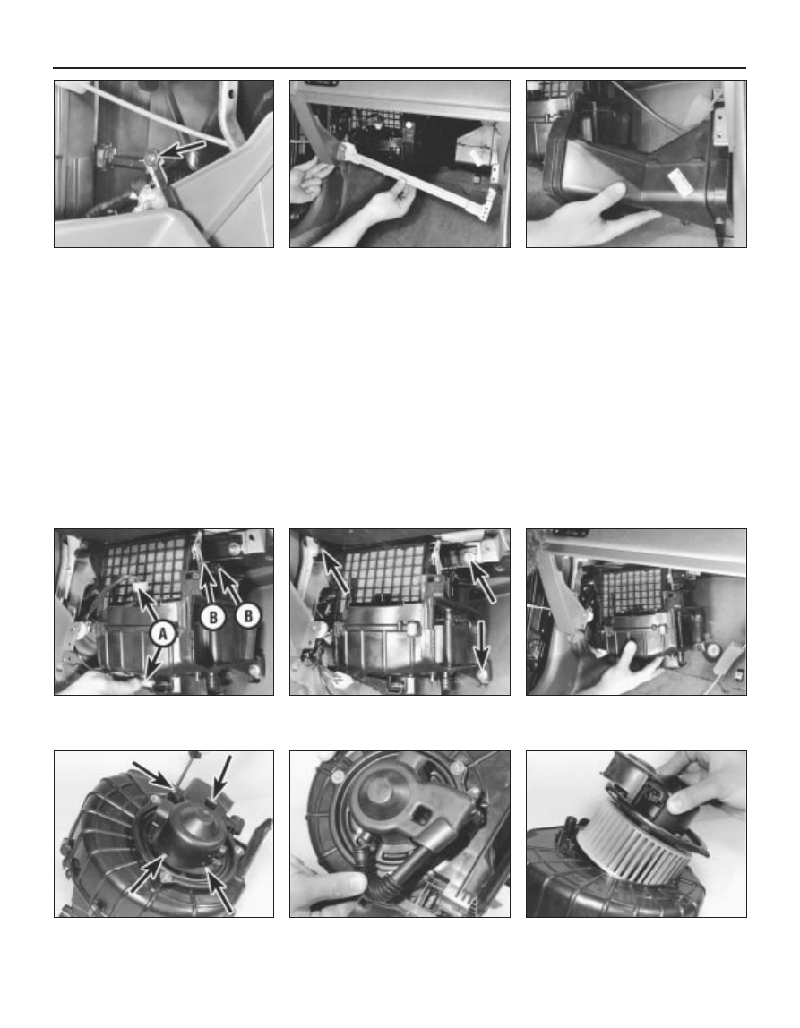
15 Undo the two glovebox retaining screws
then partially withdraw the glovebox until
access can be gained to the glovebox damper
to facia screw. Undo the damper screw and
remove the glovebox and damper (see
illustration)
.
16 Slacken and remove the four glovebox
support rail mounting bolts and remove the
rail (see illustration).
17 Slacken and remove the two retaining
screws and remove the blower motor-to-
heater unit duct (see illustration). On models
equipped with air conditioning, the evaporator
unit is fitted in place of the duct. It may be
possible to gain the necessary clearance

required to disengage the evaporator and
remove the blower motor by removing the
mounting brackets and nuts. If not, the
evaporator must be removed.
18 Disconnect the air recirculation cable
inner from the flap and free the cable outer
from the blower motor. Disconnect the two
blower motor wiring connectors (see
illustration)
.
19 Slacken and remove the three blower
motor mounting bolts and manoeuvre the
blower unit out from underneath the facia (see
illustrations)
.
20 To remove the motor from the unit, undo
the four motor cover retaining screws, then
disconnect the breather hose and lift off the

cover. Slacken and remove the three motor
retaining bolts and withdraw the motor
assembly from the blower unit. Undo the fan
retaining nut and separate the fan and motor,
noting the seal fitted between the two
components (see illustrations).

Heater blower motor resistor

21 Remove the glovebox as described in
paragraphs 15 and 16.
22 Disconnect the wiring connector, then
undo the two retaining screws and remove the
resistor from the front of the motor assembly.

Heater valve

23 Working in the engine compartment,
disconnect the cable inner from the heater

3•10 Cooling, heating and ventilation systems

10.20c  Undo motor retaining bolts and

withdraw motor from unit

10.20b  . . . and disconnect breather hose

10.20a  Remove motor cover retaining

screws (arrowed) . . .

10.19b  . . . and remove unit from behind

facia

10.19a  Undo three blower motor mounting

bolts (arrowed) . . .

10.18  Disconnect motor wiring connec-

tors (A) and air recirculation cable (B)

10.17  . . . then remove blower motor-to-

heater unit duct

10.16  Remove glovebox support rail . . .

10.15  Glovebox damper retaining screw

(arrowed)

1689 Rover 214 & 414 Updated Version 09/97

-------------------------------------------------------------------------------------------------------------------------------------------------------------

valve and free the cable outer from the
retaining clip.
24 Slacken and remove the bolt securing the
heater valve mounting bracket to the engine
compartment bulkhead.
25 Either drain the cooling system or clamp
the coolant hoses on each side of the coolant
valve to minimise the loss of coolant.
26 Slacken the hose retaining clips, then
disconnect both hoses from the coolant valve
and remove the valve from the engine
compartment. Mop up any spilt coolant
immediately.

Refitting

Heater unit

27 Refitting is a reverse of the removal
procedure, noting the following:
a)

Ensure that the heater ducts are securely
connected to the unit so that there are no
air leaks or gaps.

b)

Check the operation of all heater cables
before refitting the facia, ensuring that the
relevant component moves smoothly from
the fully open to the fully closed position.
If necessary, adjustments can be made by
releasing the relevant retaining clip and
repositioning the cable outer.

c)

Ensure that the heater hoses are correctly
reconnected and are securely held by the
retaining clips.

d)

Tighten the heater lower mounting nut to
the specified torque setting.

e)

Refill the cooling system as described in
Chapter 1.

Heater matrix

28 Refitting is a reverse of the removal
procedure.

Heater blower motor

29 Refitting is a reversal of the removal
sequence, noting the following:
a)

Ensure that the foam rubber seal is
refitted correctly so that the blower
motor-to-bulkhead aperture is closed off.

b)

Tighten the blower motor mounting bolts
to the specified torque setting.

c)

Ensure that the air recirculation cable and
flap functions correctly before refitting the
glovebox. If necessary, adjust by releasing
the cable retaining clip and repositioning
the cable outer.

Heater blower motor resistor

30 Refitting is a reverse of the removal
procedure.

Heater valve

31 Refitting is a reversal of the removal
procedure. On completion, check the heater
cable operates smoothly and replenish the
cooling system.

11 Heater ducts and vents -

removal and refitting

3

Removal

Facia ducts

Remove the facia.

The ducts are mounted on the facia
assembly and can be removed individually,
once the retaining screws have been
removed.

Heater unit ducts

The left-hand heater unit to blower 
motor duct is removed as described in
paragraphs 15 to 17 of Section 10.
To remove the right-hand duct, first remove
the facia. Slacken and remove the retaining
screw which secures the right-hand end of the
duct to the mounting bracket and release the
radio aerial from the retaining clips on the
underside of the duct. The duct can then be
manoeuvred out of position.
Removal of the lower ducts which supply
air to the rear passenger footwells is a
complex job, requiring the removal of the front
seats, centre console and the various trim
panels so that the floor carpet can be peeled
back, and is therefore not recommended.

Centre console vents

Remove the centre console.
The vents can then be unclipped from the
rear of the front console section and removed.

Facia vents

The adjustable face-level vents can be
removed by prising them gently out of the
facia until the clips are released, taking care
not to mark the facia.
The door window demister vents, fitted to
the sides of the facia, can also be prised out
of position once the relevant door has been
opened.

Refitting

10 Refitting is a reverse of the removal
procedure.

12 Heater controls - removal,

refitting and adjustment

3

Removal

Remove the heater unit.
Disconnect the heater control cables from
the heater unit and unclip the control panel.
Remove the panel assembly complete with
cables (see illustrations).

Refitting and adjustment

Refit the heater control panel to the heater
unit and reconnect the necessary control
cables to their original positions.
Check the operation of the control cables,
ensuring that they operate smoothly and
move the necessary component from the fully
open to the fully closed position. Adjustments
can be made by releasing the cable retaining
clip and repositioning the cable outer.
Once the necessary control cables are
functioning correctly, refit the heater unit.

Cooling, heating and ventilation systems  3•11

10.20e  . . . and lift off fan (seal arrowed)

10.20d  Remove fan retaining nut . . .

12.2b  . . . and remove heater control panel

with cables

12.2a  Disconnect control cables from

heater unit . . .

3

1689 Rover 214 & 414 Updated Version 09/97

-------------------------------------------------------------------------------------------------------------------------------------------------------------

13 Air conditioning compressor

drivebelt - inspection,
adjustment and renewal

Refer to Chapter 1 (alternator drivebelt check).

14 Air conditioning refrigerant -

level check

Refer to Chapter 1.

15 Air conditioning system

components 
removal and refitting

3

Warning: The air conditioning
system must be professionally
discharged before carrying out
any of the following work. Cap

or plug the pipe lines as soon as they are
disconnected to prevent the entry of
moisture.

Compressor

Removal

Remove the alternator/air conditioning
compressor drivebelt as described in Chap-
ter 1.
Disconnect the air conditioning pipes from
the compressor (see illustration).
Slacken and remove the four bolts securing
the compressor to the mounting bracket and
manoeuvre it downwards and away from the
engine.

Refitting

Refitting is a reverse of the removal
sequence, tightening the compressor
mounting bolts to the specified torque setting.
Ensure that the compressor pipe unions are
securely tightened then refit and adjust the
drivebelt as described in Chapter 1. On
completion, have the air conditioning system
recharged by a refrigeration specialist or
suitably-equipped Rover dealer.

Condenser

Removal

Remove the front bumper.
Slacken and remove the bolts securing the
power steering oil cooler to the body, then
undo the bonnet lock mounting bracket bolts
and position the lock assembly clear of the
condenser unit.
Unscrew the air conditioning pipe union
nuts from the condenser unit then disconnect
the pipes. Discard the union pipe O-rings as
these must be renewed whenever they are
disturbed.
Slacken and remove the four retaining bolts
and withdraw both the condenser upper
mounting brackets. Release the condenser
from its lower mounting points and
manoeuvre it away from the vehicle.

Refitting

Prior to refitting, check the condenser lower
mounting rubbers for signs of damage or
deterioration and renew as necessary. Renew
the pipe union O-rings.
10 Refitting is a direct reversal of the removal
procedure, tightening the pipe union nuts to
the specified torque setting. On completion,
have the air conditioning system recharged by
a refrigeration specialist or a suitably
equipped Rover dealer.

Condenser cooling fan

Removal

11 Drain the cooling system.
12 Disconnect the wiring connector from the
engine overheat switch, located in the top
coolant hose, then slacken the clips securing
the hose to the radiator and engine.
Disconnect the hose from the radiator and
engine and position it clear of the condenser
so that it does not hinder removal.
13 Disconnect the condenser fan electrical
wiring connector then undo the four fan
cowling retaining nuts and manoeuvre the
assembly out of the engine compartment.

14 To dismantle the assembly, first undo the
fan retaining nut then lift the fan off the motor
spindle. Undo the two screws which secure
the motor assembly to the cowling then
release the motor wiring and connector and
separate the motor and cowling.

Refitting

15 Refitting is a reverse of the removal
procedure, noting the following points:
a)

Ensure that the motor wiring is securely
retained by the cowling clips and is clear
of the condenser fan.

b)

Ensure that the radiator hose is securely
held by its retaining clips.

c)

On completion, refill the cooling system.

Evaporator

Removal

16 Undo the three bolts which secure the
washer system reservoir to the engine
compartment bulkhead and move the
reservoir to gain access to the two evaporator
union nuts. Slacken both the union nuts and
disconnect the pipes from the evaporator.
Remove the O-rings from the union nuts and
discard them.

3•12 Cooling, heating and ventilation systems

15.2  Air conditioning system layout

1 Compressor
2 Condenser
3 Receiver drier
4 Evaporator

5 Heater unit
6 Blower unit
7 High pressure servicing

connection

8 Low pressure servicing

connection

9 Trinary switch

1689 Rover 214 & 414 Updated Version 09/97

-------------------------------------------------------------------------------------------------------------------------------------------------------------

17 Working from inside the vehicle, undo the
two glovebox retaining screws, then partially
withdraw the glovebox until access can be
gained to the glovebox damper-to-facia
screw. Undo the damper screw and remove
the glovebox and damper.
18 Slacken and remove the four glovebox
support rail mounting bolts and remove the
rail.
19 Undo the two evaporator bracket
retaining bolts and remove both the brackets.
20 Disconnect the wiring connector from the
right-hand side of the evaporator.
21 Slacken and remove the two evaporator
mounting nuts and manoeuvre the unit out of
position.

Refitting

22 Refitting is a reverse of the removal
procedure noting the following:
a)

Ensure that the evaporator is correctly
joined to the heater unit and blower
motor, so that there are no air leaks or
gaps, then tighten the retaining nuts and
bracket bolts securely.

b)

Fit new O-rings to the pipe unions and

tighten the union nuts to the specified
torque setting.

c)

On completion, have the system
recharged by a refrigeration specialist or a
suitably-equipped Rover dealer.

Receiver drier

Removal

23 Remove the left-hand headlamp and the
battery and battery tray.
24 Undo the two screws securing the air
intake grille to the body. Disengage the grille
from the resonator and remove it from the
vehicle. Move the resonator to one side to
gain access to the receiver drier.
25 Slacken the union nuts and disconnect
the pipes from the receiver drier noting the O-
rings which are fitted to the pipe unions.
Discard the O-rings as they must be renewed
whenever they are disturbed. The receiver
drier unit unions must be capped immediately
after they are disconnected and must remain
capped until they are to be reconnected. If the
receiver drier unit is left uncapped for any
period of time it must be renewed.

26 Slacken the receiver drier clamp bolt then
slide the unit out of the retaining clamp and
remove it from the engine compartment.

Refitting

27 Refitting is a direct reversal of the removal
sequence, tightening the pipe union nuts to
the specified torque setting. On completion,
have the system recharged by a refrigeration
specialist or suitably-equipped Rover dealer.

Trinary switch

Removal

28 Remove the front bumper.
29 Disconnect the wiring connector and
unscrew the switch from the air conditioning
pipe. Remove the O-ring from the switch and
discard it.

Refitting

30 Refitting is a reverse of the removal
procedure. Fit a new O-ring to the switch and
tighten it to the specified torque setting. On
completion, have the system recharged by a
refrigeration specialist or suitably-equipped
Rover dealer.

Cooling, heating and ventilation systems  3•13

3

1689 Rover 214 & 414 Updated Version 09/97

-------------------------------------------------------------------------------------------------------------------------------------------------------------

1689 Rover 214 & 414 Updated Version 09/97

5A

Chapter 5 Part A
Ignition system - carburettor engines

Distributor - removal, overhaul and refitting  . . . . . . . . . . . . . . . . . . .

5

General information and precautions  . . . . . . . . . . . . . . . . . . . . . . . .

1

HT coil - removal, testing and refitting  . . . . . . . . . . . . . . . . . . . . . . .

4

HT leads, distributor cap and rotor arm - inspection and renewal  . .

3

Ignition amplifier module - removal and refitting . . . . . . . . . . . . . . . .

6

Ignition system - testing  . . . . . . . . . . . . . . . . . . . . . . . . . . . . . . . . . .

9

Ignition timing - checking and adjustment  . . . . . . . . . . . . . . . . . . . .

8

Spark plugs - renewal  . . . . . . . . . . . . . . . . . . . . . . . . . . . . . . . . . . . .

2

Thermostatically-operated vacuum switch - removal and refitting . .

7

5A•1

Contents

Specifications

General

System type  . . . . . . . . . . . . . . . . . . . . . . . . . . . . . . . . . . . . . . . . . . . . . .

Lucas constant energy inductive

Firing order  . . . . . . . . . . . . . . . . . . . . . . . . . . . . . . . . . . . . . . . . . . . . . . .

1-3-4-2 (No 1 cylinder at timing belt end)

Direction of crankshaft rotation  . . . . . . . . . . . . . . . . . . . . . . . . . . . . . . .

Clockwise (viewed from right-hand side of vehicle)

Distributor

Type  . . . . . . . . . . . . . . . . . . . . . . . . . . . . . . . . . . . . . . . . . . . . . . . . . . . .

Lucas 67 DM4, incorporating centrifugal and vacuum advance
mechanisms and externally-mounted amplifier module

Identification:

With catalytic converter  . . . . . . . . . . . . . . . . . . . . . . . . . . . . . . . . . . .

NJC 10026

Without catalytic converter  . . . . . . . . . . . . . . . . . . . . . . . . . . . . . . . . .

NJC 10033

Direction of rotor arm rotation  . . . . . . . . . . . . . . . . . . . . . . . . . . . . . . . .

Anti-clockwise (viewed from left-hand side of vehicle)

Pick-up coil resistance  . . . . . . . . . . . . . . . . . . . . . . . . . . . . . . . . . . . . . .

950 to 1150 ohms

Vacuum diaphragm unit identification:

With catalytic converter  . . . . . . . . . . . . . . . . . . . . . . . . . . . . . . . . . . .

80-200-8

Without catalytic converter  . . . . . . . . . . . . . . . . . . . . . . . . . . . . . . . . .

80-200-6

Vacuum advance commences  . . . . . . . . . . . . . . . . . . . . . . . . . . . . . . . .

107 mbar (80 mm Hg)

Maximum vacuum advance:

With catalytic converter  . . . . . . . . . . . . . . . . . . . . . . . . . . . . . . . . . . .

16º @ 267 mbar (200 mm Hg)

Without catalytic converter  . . . . . . . . . . . . . . . . . . . . . . . . . . . . . . . . .

12º @ 267 mbar (200 mm Hg)

Deceleration check - vacuum disconnected  . . . . . . . . . . . . . . . . . . . . .

4º to 8º @ 2500 rpm

Note: Degree and speed values to be measured at crankshaft

HT coil

Type  . . . . . . . . . . . . . . . . . . . . . . . . . . . . . . . . . . . . . . . . . . . . . . . . . . . .

AUU 1326 or ADU 8779

Manufacturer  . . . . . . . . . . . . . . . . . . . . . . . . . . . . . . . . . . . . . . . . . . . . .

Bosch, Ducellier or Rudi Cajavec

Current consumption - average  . . . . . . . . . . . . . . . . . . . . . . . . . . . . . . .

0.25 to 0.75 amps @ idle speed

Winding resistances:

Primary  . . . . . . . . . . . . . . . . . . . . . . . . . . . . . . . . . . . . . . . . . . . . . . . .

0.3 to 0.5 ohms @ 20ºC

Secondary . . . . . . . . . . . . . . . . . . . . . . . . . . . . . . . . . . . . . . . . . . . . . .

5 to 15 K ohms @ 20ºC

Ignition timing

At 1500 rpm (vacuum pipe disconnected)  . . . . . . . . . . . . . . . . . . . . . . .

9º ± 1º BTDC

Easy, suitable for
novice with little
experience

Fairly easy, suitable
for beginner with
some experience

Fairly difficult,
suitable for competent
DIY mechanic

Difficult, suitable for
experienced  DIY
mechanic

Very difficult,
suitable for expert DIY
or  professional

Degrees of difficulty

5

4

3

2

1

-------------------------------------------------------------------------------------------------------------------------------------------------------------

Torque wrench settings

Nm

lbf ft

Spark plugs . . . . . . . . . . . . . . . . . . . . . . . . . . . . . . . . . . . . . . . . . . . . . . .

25

18

Distributor cap screws  . . . . . . . . . . . . . . . . . . . . . . . . . . . . . . . . . . . . . .

2

21

Amplifier module-to-distributor body (hex-head) screws . . . . . . . . . . . .

5

4

Distributor mounting bolts  . . . . . . . . . . . . . . . . . . . . . . . . . . . . . . . . . . .

25

18

Ignition HT coil mounting bolts . . . . . . . . . . . . . . . . . . . . . . . . . . . . . . . .

7

5

5A•2 Ignition system - carburettor engines

1689 Rover 214 & 414 Updated Version 09/97

1

General information and
precautions

General information

The ignition system is fully-electronic in

operation and of the inductive type,
incorporating a contact-less distributor (driven
off the camshaft left-hand end) and an amplifier
module, as well as the spark plugs, HT leads,
ignition HT coil and associated wiring.

The system is divided into two circuits,

which are the primary (low tension/LT) and
secondary (high tension/HT). The primary
circuit consists of the battery, ignition switch,
ignition HT coil primary windings, amplifier
module and distributor pick-up coil and
wiring. The secondary circuit consists of the
ignition HT coil secondary windings, the
distributor cap and rotor arm, the spark plugs
and HT leads.

The distributor incorporates features which

advance the ignition timing both mechanically
and by vacuum operation. Its shaft, driven by
the camshaft, incorporates a reluctor which
has four shaped poles and is mounted on the
centre of a centrifugal advance assembly,
whose two weights move outwards under
centrifugal force as engine speed rises, thus
rotating the reluctor on the shaft and
advancing or retarding the spark, the amount
of movement being controlled by light
springs. A pick-up coil generates a weak
magnetic field whenever the ignition is
switched on. As the engine rotates the
reluctor poles pass the coil, disturbing the
field each time and sending a signal current to
the amplifier module. Whenever this signal
exceeds a threshold level determined by
engine speed, a high-voltage transistor in the
amplifier is switched on, thus allowing HT coil
current to flow. When this current has reached
the required level, it is held constant until the
transistor is switched off, thus triggering the
spark. The pick-up coil is clamped to a stator
pack that is able to rotate under the control of
the vacuum diaphragm unit mounted on the
side of the distributor. The unit consists of a
diaphragm, one side of which is connected
via a small-bore pipe to the carburettor and
the other side to the stator pack. Inlet
manifold depression, which varies with engine
speed and throttle position, causes the
diaphragm to move, thus rotating the stator
pack and advancing or retarding the spark.

Models fitted with catalytic converters have

a thermostatically-operated vacuum switch

screwed into the cooling system thermostat
housing. The switch is connected into the
vacuum hose linking the carburettor to the
distributor vacuum diaphragm unit. At coolant
temperatures below 70ºC, the switch cuts off
the vacuum supply to the diaphragm and
prevents the unit from advancing the ignition
timing. This causes the exhaust gas
temperatures to rise, due to the retarded
ignition timing, and brings the catalytic
converter swiftly up to its efficient operating
temperature. Once coolant temperature rises
above 70ºC, the switch opens and allows the
vacuum to reach the diaphragm unit, thus
restoring normal advance and retard of the
ignition timing.

Precautions

General

It is necessary to take extra care when

working on the electrical system to avoid
damage to semi-conductor devices (diodes
and transistors), and to avoid the risk of
personal injury. In addition to the precautions
given in the “Safety first!” Section at the
beginning of this manual, take note of the
following points when working on the system.

Always remove rings, watches, etc. before

working on the electrical system. Even with
the battery disconnected, capacitive
discharge could occur if a component live
terminal is earthed through a metal object.
This could cause a shock or nasty burn.

Do not reverse the battery connections.

Components such as the alternator or any
other having semi-conductor circuitry could
be irreparably damaged.

If the engine is being started using jump

leads and a slave battery, connect the
batteries positive to positive and negative to
negative. 
This also applies when connecting a
battery charger.

Never disconnect the battery terminals, or

alternator multi-plug connector, when the
engine is running.

The battery leads and alternator multi-plug

must be disconnected before carrying out any
electric welding on the car.

Never use an ohmmeter of the type

incorporating a hand cranked generator for
circuit or continuity testing.

Ignition and engine management
systems

The HT voltage generated by an electronic

ignition system is extremely high, and in
certain circumstances could prove fatal. Take
care to avoid receiving electric shocks from
the HT side of the ignition system. Persons

with surgically-implanted cardiac pacemaker
devices should keep well clear of the ignition
circuits, components and test equipment.

Do not handle HT leads, or touch the

distributor or coil when the engine is running.
If tracing faults in the HT circuit, use well
insulated tools to manipulate live leads.

Engine management modules are very

sensitive components. Certain precautions
must be taken to avoid damage to the module
when working on a vehicle equipped with an
engine management system, as follows.

When carrying out welding operations on

the vehicle using electric welding equipment,
the battery and alternator should be
disconnected.

Although underbonnet-mounted modules

will tolerate normal underbonnet conditions,
they can be adversely affected by excess heat
or moisture. If using welding equipment or
pressure washing equipment in the vicinity of
the module, take care not to direct heat, or
jets of water or steam at the module. If this
cannot be avoided, remove the module from
the vehicle, and protect its wiring plug with a
plastic bag.

Before disconnecting any wiring, or

removing components, always ensure that the
ignition is switched off.

On models with underbonnet-mounted

modules, do not run the engine with the
module detached from the body panel, as the
body acts as an effective heat sink and the
module may be damaged due to internal
overheating.

Do not attempt to improvise fault diagnosis

procedures using a test lamp or multimeter,
as irreparable damage could be caused to the
module.

After working on ignition/engine

management system components, ensure
that all wiring is correctly reconnected before
reconnecting the battery or switching on the
ignition.

2

Spark plugs - renewal

Refer to Chapter 1.

3

HT leads, distributor cap and
rotor arm 
- inspection and
renewal

Refer to Chapter 1.

-------------------------------------------------------------------------------------------------------------------------------------------------------------

4

HT coil - removal, 
testing and refitting

2

Removal

The coil is mounted on the left-hand side of
the engine compartment, between the battery
and the left-hand headlamp unit.
Disconnect the battery negative terminal.
To improve access to the coil, remove the
headlamp bulb cover.
Peel back the end cover, then disconnect
the HT lead from the coil. Note which
terminals they are connected to and
disconnect the two pairs of LT wires from the
coil (see illustration).
Remove the two coil mounting bolts and
withdraw the coil from the engine
compartment. If necessary, slacken the clamp
screw and separate the coil from its mounting
bracket.

Testing

Test the coil by using a multimeter, set to its
resistance function, to check the primary (LT
+ to – terminals) and secondary (LT + to HT

lead terminal) windings for continuity. The
resistance of either winding can be checked
and compared with the specified value. Note
that the resistance of the coil windings will
vary slightly according to the coil temperature.
Using an ohmmeter or continuity tester,
check that there is no continuity between the
HT lead terminal and the coil body.
If the coil is faulty it must be renewed.

Refitting

Refitting is the reverse of the removal
procedure.

5

Distributor - removal,
overhaul and refitting

3

Removal

Disconnect the battery negative terminal.
Release the wire retaining clip and unplug
the wiring connector from the ignition
amplifier module (see illustration).
Disconnect the vacuum pipe from the
vacuum diaphragm unit (see illustration).
Position the engine so that No 1 cylinder is
at TDC on the compression stroke.
Mark the relationship of the distributor body

to the cylinder head, as a guide for refitting
(see illustration).
Unscrew the distributor mounting bolts and
withdraw the distributor (see illustration). Do
not disturb the crankshaft setting while the
distributor is removed.
Remove the distributor body sealing ring
which must be renewed whenever it is
disturbed (see illustration).

Overhaul

Remove the distributor cap and withdraw
the rotor arm, if not already removed (see
illustration)
.

Ignition system - carburettor engines  5A•3

5.3  Disconnecting vacuum pipe from

distributor vacuum diaphragm unit

5.2  Disconnecting wiring connector from

ignition amplifier module

4.4  HT coil connections

3 Mounting bolts

6 LT connections

4 Clamp screw

7 HT connection

5 HT coil

5.5  Making alignment marks on distributor

body and cylinder head

5.7  . . . then remove distributor (O-ring arrowed)

5.6  Unscrew distributor mounting bolts (remaining bolt 

arrowed) . . .

5A

1689 Rover 214 & 414 Updated Version 09/97

-------------------------------------------------------------------------------------------------------------------------------------------------------------

Undo the two bolts securing the amplifier
module to the body, then carefully remove the
gasket and withdraw the connector.
10 Remove the screws and separate the
upper housing from the lower.
11 Remove the clamp ring and pick-up coil
from the upper housing.

12 Remove the circlip (and first thrustwasher,
if fitted) from the underside of the upper
housing, disengage the stator pack from the
vacuum diaphragm unit arm and withdraw the
stator pack, followed by the (second)
thrustwasher.
13 Remove the retaining screw and withdraw
the vacuum diaphragm unit from the
distributor.
14 Check the distributor shaft endfloat and if
it seems excessive, seek expert advice.
15 Remove the spring from the distributor
drive coupling, then use a scriber or similar to
mark the relationship of the coupling to the
shaft. It is essential that the coupling is refitted
correctly in relationship to the rotor arm on
refitting. Release the distributor shaft by
driving out the retaining roll pin and removing
the coupling, noting the toothed thrustwasher
which is fitted behind it.
16 Withdraw the shaft, noting the toothed
thrustwasher underneath the centrifugal
advance assembly. Be very careful not to
bend any of the reluctor poles and do not
attempt to remove it from the shaft.
17 The advance assembly and shaft can be
lubricated but if any part of the assembly is
found to be worn or damaged, then the
complete distributor must be renewed.
Individual replacement parts are not available.
18 Clean and examine all components. If any
are found to be worn or damaged, seek
expert advice. A repair kit of sundry parts is
available separately, also the coupling
assembly, the pick-up coil and vacuum
diaphragm unit, as well as the rotor arm and
the distributor cap. If any other parts are worn
or damaged, the complete distributor must be
renewed.
19 In addition to the checks in Chapter 1, use
an ohmmeter or continuity tester to check that
there is no continuity between any of the
cap’s terminal segments. Similarly, check that
there is no continuity between the rotor arm
body and its brass segment. Note that the
arm has a built-in resistance.
20 Reassembly is the reverse of the
dismantling procedure, noting the following:
a)

Apply a few drops of suitable oil to the
advance assembly pivots and springs,
also to the shaft, upper housing and
stator pack bearing surfaces.

b)

Using the marks made on dismantling, be
very careful to ensure that the coupling is
located correctly on the shaft end (in
relationship to the rotor arm) before
driving in the roll pin to secure it, then
ensure that the spring is fitted over the roll
pin ends.

c)

Grease the vacuum diaphragm unit arm
before refitting it and use grease to stick
the thrustwasher to the underside of the
upper housing. Refit the stator pack,
ensuring it engages correctly with the
vacuum diaphragm unit arm peg, followed
by the (remaining thrustwasher, if fitted,
and) circlip. Tighten the unit retaining
screw securely.

d)

Refit the pick-up coil to the upper housing
and centre its terminals in the aperture
before fitting the clamp ring so that its
cut-out is over the aperture.

e)

Refit the upper housing to the lower,
tighten the screws lightly and check that
the shaft is free to rotate. There must be
no sign of the reluctor poles touching the
stator pack arms, as either can easily be
bent. Tighten the screws securely.

f)

Refit the connector and its gasket.

g)

Refit the amplifier module and the rotor
arm.

h)

Fit a new sealing ring to the distributor
body.

Refitting

Original distributor

21 Ensure that No 1 cylinder is at TDC, then
rotate the rotor arm to align with the
distributor cap’s No 1 terminal. Fit a new
sealing ring to the distributor body and
lubricate it with a smear of engine oil.
22 Align the marks made on removal and refit
the distributor to the cylinder head. If
necessary, rotate the rotor arm very slightly to
help the distributor drive dogs locate in the
camshaft slots; they are offset and so will fit
only one way. Refit the distributor mounting
bolts and tighten them to the specified torque.
23 Refit the spark plugs.
24 Refit the distributor cap, ensuring it is
correctly located, and tighten its retaining
screws to the specified torque. Reconnect the
HT leads to the relevant spark plugs.
25 Reconnect the vacuum pipe to the
vacuum diaphragm unit and the wiring
connector to the ignition amplifier module.
26 Check and, if necessary, adjust the
ignition timing.

New distributor

27 If a new distributor is to be fitted (or no
marks were made on removal), the following
procedure will produce a basic setting which
will enable the engine to start and run while
the ignition timing is accurately set.
28 Position the engine so that No 1 cylinder
is at TDC on the compression stroke.
29 Rotate the crankshaft slightly anti-
clockwise until the pulley notch is positioned
in the 9º BTDC position (between the 8 and 12
marks on the timing scale).
30 Rotate the distributor rotor arm to align
with the distributor cap’s No 1 terminal. This
terminal is marked with a K which is cast on
the outside of the distributor cap. Fit a new
sealing ring to the distributor body and
lubricate it with a smear of engine oil.
31 Fit the distributor to the cylinder head and
refit its mounting bolts. Positioning the
distributor body so that the mounting bolts
are in the middle of their respective slots then
tighten the bolts finger-tight only.
32 Perform the operations given in
paragraphs 23 to 25.
33 Check and adjust the ignition timing.

5A•4 Ignition system - carburettor engines

5.8  Lucas 67 DM4 distributor

1 Distributor cap
2 Rotor arm
3 Upper housing
4 Vacuum diaphragm unit
5 Stator pack including thrustwasher(s) and

circlip

6 Pick-up coil
7 Clamp ring
8 Distributor shaft, including reluctor and

advance assembly

9 Thrustwasher

10 Lower housing
11 O-ring
12 Drive coupling, including thrustwasher,

spring and roll pin

13 Connector and gasket
14 Amplifier module

1689 Rover 214 & 414 Updated Version 09/97

-------------------------------------------------------------------------------------------------------------------------------------------------------------

6

Ignition amplifier module -
removal and refitting

2

Warning: Do not attempt to
open or repair the ignition
amplifier module. If faulty, it
must be renewed.

Removal

Disconnect the battery negative terminal.
Releasing its wire clip, unplug the wiring
connector from the amplifier module.
Remove the two bolts and withdraw the
module, taking care not to damage the
terminal pins.
Check carefully that the mating surfaces of
the module and distributor are completely
clean and unmarked and that the pick-up coil
terminal pins are clean and a secure fit in the
module. If in doubt, it is permissible to remove
the connector and its gasket and to gently
squeeze together the female terminals to
improve the fit.
The pick-up coil-to-connector and
connector-to-module connections must be
checked with particular care if the module is
thought to be faulty. Similarly, check, clean
and tighten (if necessary) the distributor wiring
connector-to-module terminals. It is essential
that there is good electrical contact between
the module and the distributor and at all four
LT wiring connections mentioned above.

Refitting

On refitting, apply a smear of heat-
conducting silicone grease to the mating
surfaces of the module and distributor. The
correct grease can be obtained from Rover
dealers under Part Number BAU 5812 but if
this is not available, either a heat-sink
compound or an anti-seize compound (such
as Holt’s Copaslip), will serve as an adequate
substitute.
Check that the terminal pins are not bent or
damaged and that they engage correctly with
the module’s connections.
Tighten the module retaining bolts to the
specified torque wrench setting, then
reconnect the distributor wiring and battery.

7

Thermostatically-operated
vacuum switch 

removal and refitting

2

On models fitted with a catalytic converter,
a thermostatically-operated vacuum switch is
screwed into the cooling system thermostat
housing.

Removal

Either drain the cooling system or be
prepared for some loss of coolant as the
switch is unscrewed.
Access to the thermostat housing is

possible with the inlet manifold and
carburettor in place, but is made much easier
if these are first removed.
Disconnect and plug the switch vacuum
pipes.
Unscrew the switch and withdraw it, then
plug the opening to prevent the entry of dirt. If
the cooling system has not been drained,
work quickly to minimise coolant loss.
If required, the switch can be tested as
described in Chapter 3.

Refitting

Refitting is the reverse of the removal
procedure, noting the following:
a)

Wipe clean the threads of the switch and
thermostat housing.

b)

If a sealing washer is fitted, renew it
whenever it is disturbed so as to prevent
leaks. If no sealing washer is fitted, apply
a smear of sealant to the switch threads.

c)

Tighten the switch securely and
reconnect the vacuum pipes.

d)

Refit any components removed to
improve access.

e)

Replenish the cooling system.

8

Ignition timing 
checking and adjustment

Refer to Chapter 1.

9

Ignition system - testing

3

Note: Always switch off the ignition before
disconnecting or connecting any system
component and when using a multi-meter to
check resistances. Any voltmeter or multi-
meter used to test ignition system
components must have an impedance of 
10 Mohms or greater.

General

The components of electronic ignition
systems are normally very reliable. Most faults
are likely to be due to loose or dirty
connections or to ‘tracking’ of HT voltage due
to dirt, dampness or damaged insulation, than
to the failure of any of the system’s
components. Always check all wiring
thoroughly before condemning an electrical
component and work methodically to
eliminate all other possibilities before deciding
that a particular component is faulty.
The old practice of checking for a spark by
holding the live end of an HT lead a short
distance away from the engine is not
recommended. Not only is there a high risk of
a powerful electric shock but the HT coil or
amplifier module will be damaged. Never try
to diagnose misfires by pulling off one HT lead
at a time.

Engine will not start

If the engine will not turn over at all or only
turns very slowly, check the battery and
starter motor. Connect a voltmeter across the
battery terminals (meter positive probe to
battery positive terminal), disconnect the
ignition coil HT lead from the distributor cap
and earth it, then note the voltage reading
obtained while turning over the engine on the
starter for (no more than) ten seconds. If the
reading obtained is less than approximately
9.5 volts, check the battery, starter motor and
charging system.
If the engine turns over at normal speed but
will not start, check the HT circuit by
connecting a timing light (following the
manufacturer’s instructions) and turning the
engine over on the starter motor. If the light
flashes then voltage is reaching the spark
plugs, so these should be checked first. If the
light does not flash, check the HT leads
themselves followed by the distributor cap,
carbon brush and rotor arm.
If there is a spark, check the fuel system for
faults.
If there is still no spark, check the voltage at
the ignition HT coil + terminal. It should be the
same as the battery voltage (ie: at least 
11.7 volts). If the voltage at the coil is more
than 1 volt less than that at the battery, check
the feed back through the fusebox and
ignition switch to the battery and its earth until
the fault is found.
If the feed to the HT coil is sound, check the
coil’s primary and secondary winding
resistance. Renew the coil if faulty but be
careful to carefully check the condition of the
LT connections themselves before doing so,
to ensure that the fault is not due to dirty or
poorly-fastened connectors.
If the HT coil is in good condition, the fault
is probably within the amplifier module or
distributor pick-up coil. So that the operation
of these two can be checked quickly, Rover
dealers have a neon indicator, which when
connected across the HT coil’s LT terminals,
flashes every time the amplifier triggers an HT
pulse in the coil if the ignition is switched on
and the engine is turned over on the starter.
Owners can substitute a low-wattage bulb. If
the bulb flickers or flashes when the engine is
turned over, the amplifier and distributor are
sound.
If the amplifier and distributor are sound,
and the entire LT circuit is in good condition,
the fault, if it lies in the ignition system, must
be in the HT circuit components. These
should be checked carefully, as outlined
above.
10 If the indicator or bulb does not flash, the
fault is in either the distributor pick-up coil or
the amplifier module. Owners should note that
by far the commonest cause of failure of
either of these is a poor connection, either
between the amplifier module and the
distributor body or in the LT circuit wiring
connections themselves. If a voltmeter or

Ignition system - carburettor engines  5A•5

5A

1689 Rover 214 & 414 Updated Version 09/97

-------------------------------------------------------------------------------------------------------------------------------------------------------------

multi-meter is available, check the feed to the
amplifier (the voltage reading obtained should
be the same as that measured at the HT coil
LT + terminal), then check that there is no
measurable resistance between the amplifier
module fixing screws and engine earth and
that there is no continuity between either
module terminal and earth. If any doubt exists
as to the condition of the connections,
remove the module, clean and check carefully
the module earth and the connections and, if
necessary, improve their fit. If these checks
fail to correct the fault, measure the resistance
of the pick-up coil, comparing it with the
specified value. Renew the coil if the reading
obtained differs significantly from that given. If

the fault still exists, the only solution is to try
the effect of renewing the amplifier module.

Engine misfires

11 An irregular misfire suggests either a
loose connection or intermittent fault on the
primary circuit, or an HT fault on the coil side
of the rotor arm.
12 With the ignition switched off, check
carefully through the system ensuring that all
connections are clean and securely fastened. If
the equipment is available, check the LT circuit
as described in paragraphs 6 to 10 above.
13 Check that the HT coil, the distributor 
cap and the HT leads are clean and dry.
Check the leads themselves and the spark

plugs (by substitution, if necessary), then
check the distributor cap, carbon brush and
rotor arm.
14 Regular misfiring is almost certainly due to
a fault in the distributor cap, HT leads or spark
plugs. Use a timing light to check whether HT
voltage is present at all leads.
15 If HT voltage is not present on any
particular lead, the fault will be in that lead or
in the distributor cap. If HT is present on all
leads, the fault will be in the spark plugs.
Check and renew them if there is any doubt
about their condition.
16 If no HT is present, check the HT coil as
its secondary windings may be breaking
down under load.

5A•6 Ignition system - carburettor engines

1689 Rover 214 & 414 Updated Version 09/97

-------------------------------------------------------------------------------------------------------------------------------------------------------------

1689 Rover 214 & 414 Updated Version 09/97

5B

Chapter 5 Part B 
Ignition system - fuel injection engines

Crankshaft sensor and reluctor ring - removal and refitting  . . . . . . .

6

Distributor - removal and refitting  . . . . . . . . . . . . . . . . . . . . . . . . . . .

5

Engine management electronic control unit (ECU) - removal and 

refitting . . . . . . . . . . . . . . . . . . . . . . . . . . . . . . . . . . . . . . . . . . . . . .

7

General information and precautions  . . . . . . . . . . . . . . . . . . . . . . . .

1

HT coil - removal, testing and refitting  . . . . . . . . . . . . . . . . . . . . . . .

4

HT leads, distributor cap and rotor arm - inspection and renewal  . .

3

Ignition system - testing  . . . . . . . . . . . . . . . . . . . . . . . . . . . . . . . . . .

9

Ignition timing - checking and adjustment  . . . . . . . . . . . . . . . . . . . .

8

Spark plugs - renewal  . . . . . . . . . . . . . . . . . . . . . . . . . . . . . . . . . . . .

2

5B•1

Contents

Specifications

General

System types  . . . . . . . . . . . . . . . . . . . . . . . . . . . . . . . . . . . . . . . . . . . . .

Rover/Motorola Modular Engine Management System (MEMS), fully
electronic, controlled by ECU. Either single-point (SPi) or multi-point
(MPi) fuel injection.

Firing order  . . . . . . . . . . . . . . . . . . . . . . . . . . . . . . . . . . . . . . . . . . . . . . .

1-3-4-2 (No 1 cylinder at timing belt end)

Direction of crankshaft rotation  . . . . . . . . . . . . . . . . . . . . . . . . . . . . . . .

Clockwise (viewed from right-hand side of vehicle)

Distributor

Type  . . . . . . . . . . . . . . . . . . . . . . . . . . . . . . . . . . . . . . . . . . . . . . . . . . . .

Spark distribution only (ignition timing controlled by ECU)

Direction of rotor arm rotation  . . . . . . . . . . . . . . . . . . . . . . . . . . . . . . . .

Anti-clockwise (viewed from left-hand side of vehicle)

Distributor cap:

SPi . . . . . . . . . . . . . . . . . . . . . . . . . . . . . . . . . . . . . . . . . . . . . . . . . . . .

AUU 1186

MPi  . . . . . . . . . . . . . . . . . . . . . . . . . . . . . . . . . . . . . . . . . . . . . . . . . . .

NJD 10010

Rotor arm  . . . . . . . . . . . . . . . . . . . . . . . . . . . . . . . . . . . . . . . . . . . . . . . .

AUU 1641 (resistive type)

Engine management Electronic Control Unit (ECU)

SPi:

With catalytic converter  . . . . . . . . . . . . . . . . . . . . . . . . . . . . . . . . . . .

MNE 10008, MNE 10023 or MNE 10042

Without catalytic converter  . . . . . . . . . . . . . . . . . . . . . . . . . . . . . . . . .

MNE 10011, MNE 10013 or MNE 10051

MPi:

Alloy inlet manifold  . . . . . . . . . . . . . . . . . . . . . . . . . . . . . . . . . . . . . . .

MNE 101470

Plastic inlet manifold . . . . . . . . . . . . . . . . . . . . . . . . . . . . . . . . . . . . . .

MKC 101730

Ignition timing @ idle speed (ECU-controlled)

SPi with catalytic converter - by ECU number (vacuum pipe connected) :

MNE 10008  . . . . . . . . . . . . . . . . . . . . . . . . . . . . . . . . . . . . . . . . . . . . .

13º ± 2º BTDC

MNE 10023, MNE 10042  . . . . . . . . . . . . . . . . . . . . . . . . . . . . . . . . . .

14º ± 2º BTDC

SPi without catalytic converter - by ECU number (vacuum pipe connected) :

MNE 10011  . . . . . . . . . . . . . . . . . . . . . . . . . . . . . . . . . . . . . . . . . . . . .

13 ± 2º BTDC

MNE 10013, MNE 10051  . . . . . . . . . . . . . . . . . . . . . . . . . . . . . . . . . .

14 ± 2º BTDC

MPi - by ECU number (vacuum pipe connected) :

MNE 101470, MKC 101730  . . . . . . . . . . . . . . . . . . . . . . . . . . . . . . . .

10 ± 5º BTDC

Note: Nominal value given for checking purposes only - not adjustable and may vary under ECU control

Easy, suitable for
novice with little
experience

Fairly easy, suitable
for beginner with
some experience

Fairly difficult,
suitable for competent
DIY mechanic

Difficult, suitable for
experienced  DIY
mechanic

Very difficult,
suitable for expert DIY
or  professional

Degrees of difficulty

5

4

3

2

1

-------------------------------------------------------------------------------------------------------------------------------------------------------------

1

General information and
precautions

General information

The ignition system is fully electronic in

operation, incorporating an Electronic Control
Unit (mounted on the engine compartment
bulkhead), a distributor (driven off the inlet
camshaft left-hand end) and a crankshaft
sensor (mounted in the left-hand rear end of
the engine cylinder block/crankcase) which
registers with the reluctor ring fixed to the
flywheel. The system also incorporates spark
plugs, HT leads, an ignition HT coil and
associated wiring.

The system is divided into two circuits,

which are the primary (low tension/LT) and
secondary (high tension/HT) circuits. The
primary circuit consists of the battery, ignition
switch, ignition HT coil primary windings, ECU
and wiring. The secondary circuit consists of
the ignition HT coil secondary windings, the
distributor cap and rotor arm, the spark plugs
and the interconnecting HT leads.

The ECU controls both the ignition system

and the fuel injection system, integrating the
two in a complete engine management
system. Refer to Chapter 4 for information on
any part of the system not given in this
Chapter.

As far as the ignition system is concerned,

the ECU receives information in the form of
electrical impulses or signals from the
crankshaft sensor (which gives it the engine
speed and crankshaft position), from the
coolant temperature sensor (which gives it the
engine temperature), from the throttle pedal
switch (which tells it when the throttle is

closed) and from the manifold absolute
pressure sensor (which gives it the load on the
engine). All these signals are compared by the
ECU, using digital techniques, with set values
pre-programmed (mapped) into its memory.
Based on this information, the ECU selects
the ignition timing appropriate to those values
and controls the ignition HT coil accordingly.

This means that the distributor is just that, a

distributor of the HT pulse to the appropriate
spark plug. It has no effect whatsoever on the
ignition timing. Also, the system is so sensitive
that, at idle speed, the ignition timing may be
constantly changing. This should be
remembered if trying to check the ignition
timing.

Precautions

Refer to Part A of this Chapter.

2

Spark plugs - renewal

Refer to Chapter 1.

3

HT leads, distributor cap and
rotor arm 
- inspection and
renewal 

Refer to Chapter 1. Note the anti-flash
shield fitted beneath the rotor arm.

4

HT coil - removal, 
testing and refitting

Refer to Section 4 in Part A of this Chapter.

5

Distributor 
removal and refitting

3

Removal

Disconnect the battery negative terminal.
Disconnect the HT leads from the spark
plugs.
Undo the two distributor cap retaining screws
and remove the cap and leads as an assembly.
Slacken and remove the grub screw
securing the rotor arm to the camshaft end
then pull off the rotor arm (see illustration).
Remove the distributor cap insulating plate
from the cylinder head.
Examine each components for signs of
wear or damage and renew as necessary.

Refitting

Refitting is a reverse of the removal
procedure. Tighten the rotor arm grub screw
and distributor cap screws to the specified
torque settings.

Crankshaft sensor

Type  . . . . . . . . . . . . . . . . . . . . . . . . . . . . . . . . . . . . . . . . . . . . . . . . . . . .

ADU 7340

HT coil

Type:

SPi . . . . . . . . . . . . . . . . . . . . . . . . . . . . . . . . . . . . . . . . . . . . . . . . . . . .

NEC 10002 or NEC 10003

MPi  . . . . . . . . . . . . . . . . . . . . . . . . . . . . . . . . . . . . . . . . . . . . . . . . . . .

NEC 10002, NEC 10003 or NEC 10004

Manufacturer  . . . . . . . . . . . . . . . . . . . . . . . . . . . . . . . . . . . . . . . . . . . . .

Bosch, Ducellier or Rudi Cajavec

Current consumption - average  . . . . . . . . . . . . . . . . . . . . . . . . . . . . . . .

0.25 to 0.75 amps @ idle speed

Winding resistances:

Primary:

Spi  . . . . . . . . . . . . . . . . . . . . . . . . . . . . . . . . . . . . . . . . . . . . . . . . . .

0.3 to 0.5 ohms @ 20ºC

Mpi  . . . . . . . . . . . . . . . . . . . . . . . . . . . . . . . . . . . . . . . . . . . . . . . . .

0.7 to 0.8 ohms @ 20ºC

Secondary . . . . . . . . . . . . . . . . . . . . . . . . . . . . . . . . . . . . . . . . . . . . . .

5 to 15 K ohms @ 20ºC

Torque wrench settings

Nm

lbf ft

Spark plugs . . . . . . . . . . . . . . . . . . . . . . . . . . . . . . . . . . . . . . . . . . . . . . .

25

18

Distributor cap screws  . . . . . . . . . . . . . . . . . . . . . . . . . . . . . . . . . . . . . .

2

1

Distributor rotor arm grub screw  . . . . . . . . . . . . . . . . . . . . . . . . . . . . . .

10

7

Reluctor ring to flywheel setscrews  . . . . . . . . . . . . . . . . . . . . . . . . . . . .

3

2

Ignition HT coil mounting screws  . . . . . . . . . . . . . . . . . . . . . . . . . . . . . .

7

5

Crankshaft sensor mounting screws  . . . . . . . . . . . . . . . . . . . . . . . . . . .

6

4

Crankshaft sensor lead-to-flywheel cover plate screw  . . . . . . . . . . . . .

6

4

5B•2 Ignition system – fuel injection engines

5.4  Distributor assembly

1

Distributor cap

3 Grub screw

2

Rotor arm

4 Insulating plate

1689 Rover 214 & 414 Updated Version 09/97

-------------------------------------------------------------------------------------------------------------------------------------------------------------

6

Crankshaft sensor and
reluctor ring 
- removal and
refitting

3

Removal

Crankshaft sensor

Disconnect the battery negative terminal.
Disconnect the sensor wiring at its
connector plug on the flywheel rear cover
plate, then undo the retaining screw to release
the wiring lead.
Remove the two retaining screws and
withdraw the sensor from the cylinder
block/crankcase 

(see illustration).

Inspect the sensor for obvious signs of wear
or damage and renew it if necessary. No data
is available to enable the sensor to be tested. If
thought to be faulty, it can be checked only by
substitution with a new component.

Reluctor ring

Remove the flywheel.
Undo the two screws securing the reluctor
ring to the rear of the flywheel and withdraw it
(see illustration).

Check the ring for obvious signs of wear or
damage and renew it if necessary.

Refitting

Crankshaft sensor

Ensure that the sensor and cylinder
block/crankcase mating surfaces are clean
then refit the sensor and tighten its retaining
screws to the specified torque.
Connect the sensor wiring connector and
tighten the connector mounting screw to the
specified torque.
10 Reconnect the battery negative terminal.

Reluctor ring

11 Refitting is a reversal of the removal
procedure. Tighten the reluctor retaining
screws to the specified torque.

7

Engine management
electronic control unit (ECU)
- removal and refitting

Refer to Chapter 4.

8

Ignition timing 
checking and adjustment

Refer to Chapter 1.

9

Ignition system - testing

5

If a fault appears in the engine management
(ignition/fuel) system, first ensure that the fault
is not due to poor maintenance. Check that
the air cleaner filter element is clean, the spark
plugs are in good condition and correctly
gapped, and that the engine breather hoses
are clear and undamaged. Also check that the
accelerator cable is correctly adjusted. If the
engine is running very roughly, check the
compression pressures, bearing in mind that
possibly one of the hydraulic tappets might be
faulty, producing an incorrect valve clearance.
If these checks fail to reveal the cause of
the problem, the vehicle should be taken to a
suitably-equipped Rover dealer for testing. A
wiring block connector is incorporated in the
engine management circuit into which a
special electronic diagnostic tester can be
plugged. The tester will locate the fault quickly
and simply, alleviating the need to test all the
system components individually, which is a
time-consuming operation that carries a high
risk of damaging the ECU.
The only ignition system checks which can
be carried out by the home mechanic are
those described for the spark plugs, HT leads,
rotor arm and distributor cap (Chapter 1), and
the ignition HT coil (this Chapter). If
necessary, the system wiring and wiring
connectors can be checked as described in
Chapter 12, ensuring that the ECU wiring
connectors have first been disconnected.

Ignition system – fuel injection engines  5B•3

6.3  Removing crankshaft sensor (wiring

lead screw arrowed)

6.6  Reluctor ring-to-flywheel screws

(arrowed)

5B

1689 Rover 214 & 414 Updated Version 09/97

-------------------------------------------------------------------------------------------------------------------------------------------------------------

1689 Rover 214 & 414 Updated Version 09/97

5C

Chapter 5 Part C
Starting and charging systems

Alternator - removal and refitting  . . . . . . . . . . . . . . . . . . . . . . . . . . .

8

Alternator brush holder and voltage regulator - renewal  . . . . . . . . .

7

Alternator drivebelt - inspection, adjustment and renewal  . . . . . . . .

6

Battery - maintenance . . . . . . . . . . . . . . . . . . . . . . . . . . . . . . . . . . . .

2

Battery - removal and refitting  . . . . . . . . . . . . . . . . . . . . . . . . . . . . .

4

Battery - testing and charging . . . . . . . . . . . . . . . . . . . . . . . . . . . . . .

3

Charging system - testing  . . . . . . . . . . . . . . . . . . . . . . . . . . . . . . . . .

5

General information and precautions  . . . . . . . . . . . . . . . . . . . . . . . .

1

Starter motor - brush and solenoid renewal  . . . . . . . . . . . . . . . . . . . 11
Starter motor - removal and refitting . . . . . . . . . . . . . . . . . . . . . . . . . 10
Starting system - testing  . . . . . . . . . . . . . . . . . . . . . . . . . . . . . . . . . .

9

5C•1

Contents

Specifications

System

Type  . . . . . . . . . . . . . . . . . . . . . . . . . . . . . . . . . . . . . . . . . . . . . . . . . . . .

12 volt, negative earth

Battery

Type  . . . . . . . . . . . . . . . . . . . . . . . . . . . . . . . . . . . . . . . . . . . . . . . . . . . .

Maintenance-free (sealed for life) lead-acid

Lucas code:

Standard equipment  . . . . . . . . . . . . . . . . . . . . . . . . . . . . . . . . . . . . . .

063

Cold climates  . . . . . . . . . . . . . . . . . . . . . . . . . . . . . . . . . . . . . . . . . . .

063S

Performance:

Cold cranking

Reserve capacity

063  . . . . . . . . . . . . . . . . . . . . . . . . . . . . . . . . . . . . . . . . . . . . . . . . . . .

360 amps

60 amps

063S  . . . . . . . . . . . . . . . . . . . . . . . . . . . . . . . . . . . . . . . . . . . . . . . . . .

405 amps

70 amps

Alternator

Type  . . . . . . . . . . . . . . . . . . . . . . . . . . . . . . . . . . . . . . . . . . . . . . . . . . . .

Lucas/Magneti Marelli A127-65

Output - @ 14 volts and 6000 rpm  . . . . . . . . . . . . . . . . . . . . . . . . . . . . .

65 amps

Regulated voltage . . . . . . . . . . . . . . . . . . . . . . . . . . . . . . . . . . . . . . . . . .

14 volts maximum

Brush minimum protrusion  . . . . . . . . . . . . . . . . . . . . . . . . . . . . . . . . . . .

5.0 mm approx.

Voltage regulator  . . . . . . . . . . . . . . . . . . . . . . . . . . . . . . . . . . . . . . . . . .

Lucas 21TR

Starter motor

Type  . . . . . . . . . . . . . . . . . . . . . . . . . . . . . . . . . . . . . . . . . . . . . . . . . . . .

Lucas M79

Rating  . . . . . . . . . . . . . . . . . . . . . . . . . . . . . . . . . . . . . . . . . . . . . . . . . . .

0.8 kW

Brush minimum length  . . . . . . . . . . . . . . . . . . . . . . . . . . . . . . . . . . . . . .

3.5 mm approx.

Torque wrench settings

Nm

lbf ft

Alternator

Pulley retaining nut  . . . . . . . . . . . . . . . . . . . . . . . . . . . . . . . . . . . . . . . . .

25

18

Mounting/pivot/adjusting arm bolts  . . . . . . . . . . . . . . . . . . . . . . . . . . . .

25

18

Starter motor

Motor-to-gearbox bolts  . . . . . . . . . . . . . . . . . . . . . . . . . . . . . . . . . . . . .

45

33

Motor support bracket fasteners:

Bracket front half-to-motor nuts  . . . . . . . . . . . . . . . . . . . . . . . . . . . . .

25

18

Bracket front half-to-rear half bolt  . . . . . . . . . . . . . . . . . . . . . . . . . . .

45

33

Bracket rear half-to-gearbox bolts  . . . . . . . . . . . . . . . . . . . . . . . . . . .

25

18

Easy, suitable for
novice with little
experience

Fairly easy, suitable
for beginner with
some experience

Fairly difficult,
suitable for competent
DIY mechanic

Difficult, suitable for
experienced  DIY
mechanic

Very difficult,
suitable for expert DIY
or  professional

Degrees of difficulty

5

4

3

2

1

-------------------------------------------------------------------------------------------------------------------------------------------------------------

1

General information and
precautions

General information

The electrical system is of the 12 volt

negative earth type and comprises a 12 volt
battery, alternator with integral voltage
regulator, starter motor and related electrical
accessories, components and wiring. The
battery is charged by an alternator which is
belt-driven. 

The starter motor is of the pre-engaged

type incorporating an integral solenoid. On
starting, the solenoid moves the drive pinion
into engagement with the flywheel ring gear
before the starter motor is energised. Once
the engine has started, a one-way clutch
prevents the motor armature being driven 
by the engine until the pinion disengages 
from the flywheel.

Precautions

It is necessary to take extra care when

working on the electrical system to avoid
damage to semi-conductor devices (diodes
and transistors), and to avoid the risk of
personal injury. In addition to the precautions
given in the “Safety first!” Section at the
beginning of this manual, take note of the
following points when working on the system.

Always remove rings, watches, etc before

working on the electrical system. Even with
the battery disconnected, capacitive
discharge could occur if a component live
terminal is earthed through a metal object.
This could cause a shock or nasty burn.

Do not reverse the battery connections.

Components such as the alternator or any
other having semi-conductor circuitry could
be irreparably damaged.

If the engine is being started using jump

leads and a slave battery, connect the
batteries positive to positive and negative to
negative. 
This also applies when connecting a
battery charger.

Always ensure that the battery negative

lead is disconnected when working on the
electrical system.

Do not allow the engine to turn the

alternator when the alternator is not
connected.

Never test for alternator output by ‘flashing’

the output lead to earth.

Never disconnect the battery terminals, or

alternator multi-plug connector, when the
engine is running.

The battery leads and alternator multi-plug

must be disconnected before carrying out any
electric welding on the vehicle.

Never use an ohmmeter of the type

incorporating a hand cranked generator for
circuit or continuity testing.

2

Battery - maintenance

Refer to Chapter 1 and “Weekly Checks”.

3

Battery 
testing and charging

2

Warning: Specially rapid ‘boost’
charges which are claimed to
restore the power of a battery in

1 to 2 hours are not recommended as they
can cause serious damage to the battery
plates through overheating.

Warning: During battery
electrolyte replenishment, never
add water to sulphuric acid

otherwise it will explode. Always pour the
acid slowly onto the water.

Warning: The battery will be
emitting significant quantities of
highly inflammable hydrogen

gas during charging and for approximately
15 minutes afterwards. Do not allow
sparks or naked flames near the battery or
it may explode.

Testing

In normal use, the battery should not
require charging from an external source
unless very heavy use is made of electrical
equipment over a series of journeys that are
too short to allow the charging system to keep
pace with demand. Otherwise, a need for
regular recharging points to a fault either in
the battery or in the charging system.
If the vehicle is laid up for long periods (in
excess of thirty days at a time) the battery will
lose approximately 1% of its charge per week.
This figure is for a disconnected battery. If the
battery is left connected, circuits such as the
clock (where fitted) will drain it at a faster rate.
To prevent this happening, always disconnect
the battery negative lead whenever the vehicle
is to be laid up for a long period. To keep the
battery fully charged, it should be given
regular ‘refresher’ charges every six weeks or
so. This is particularly important on
‘maintenance-free’ batteries, which will suffer
permanent reduction of charge capacity if
allowed to become fully discharged.
If a discharged battery is suspected, the
simplest test for most owners is as follows.
Leave the battery disconnected for at least two
hours, then measure the (open circuit, or no-load)
voltage using a sensitive voltmeter connected
across the battery terminals. Compare the
reading obtained with the following:
Voltmeter reading

Charge condition

0.50 volts

Fully discharged - 

battery scrap

12.30 volts

50% charged

12.48 volts

75% charged

12.66 volts or more

Fully charged

If frequent topping-up is required and the
battery case is not fractured, then the battery
is being over-charged and the voltage
regulator will have to be checked.
If the vehicle covers a very small annual
mileage, it is worthwhile checking the specific
gravity of the electrolyte every three months
to determine the state of charge of the
battery. Use a hydrometer to make the check
and compare the results with the following
table:

Normal climates

Tropics

Discharged

1.120

1.080

Half charged

1.200

1.160

Fully charged

1.280

1.230

If the battery condition is suspect, first
check the specific gravity of electrolyte in
each cell. A variation of 0.040 or 
more between any cells indicates loss of
electrolyte or deterioration of the internal
plates.
A further test can be made only by a battery
specialist using a battery heavy discharge
meter. Alternatively, connect a voltmeter
across the battery terminals and operate the
starter motor with the ignition coil HT lead
disconnected from the distributor and
earthed, and with the headlamps, heated rear
window and heater blower switched on. If the
voltmeter reading remains above
approximately 9.5 volts, the battery condition
is satisfactory. If the voltmeter reading drops
below 9.5 volts and the battery has already
been charged, it is proven faulty.

Charging

In winter when heavy demand is placed on
the battery (starting from cold and using more
electrical equipment), it is a good idea
occasionally to have the battery fully charged
from an external source. The battery’s bench
charge rate depends on its code (see a 
Rover dealer or Lucas agent for details). 
For most owners, the best method will be to
use a trickle-charger overnight, charging 
at a rate of 1.5 amps. Rapid ‘boost’ charges
which are claimed to restore the power of 
the battery in 1 to 2 hours are not
recommended, as they can cause serious
damage to the battery plates through
overheating and may cause a sealed battery
to explode.
Ideally, the battery should be removed from
the vehicle before charging and moved to a
well-ventilated area. As a minimum
precaution, both battery terminal leads must
be disconnected (negative lead first) before
connecting the charger leads.
10 Continue to charge the battery until all
cells are gassing vigorously and no further rise
in specific gravity or increase in no-load
voltage is noted over a four-hour period.
When charging is complete, turn the charger
off before disconnecting the leads from the
battery.

5C•2 Starting and charging systems

1689 Rover 214 & 414 Updated Version 09/97

-------------------------------------------------------------------------------------------------------------------------------------------------------------

4

Battery 
removal and refitting

1

Removal

First check that all electrical components
are switched off to avoid a spark occurring as
the negative lead is disconnected. If the
radio/cassette unit has a security code, de-
activate the code temporarily and re-activate
it when the battery is re-connected. Refer to
the instructions and code supplied with the
unit.
Slacken the terminal clamp nut then lift the
clamp and negative (–) lead from the terminal.
This is the terminal to disconnect before
working on any electrical component on the
vehicle. If the terminal is tight, carefully ease it
off by moving it from side to side.
Raise the plastic cover from the positive (+)
terminal clamp and slacken the clamp nut,
then lift the clamp and lead from the terminal.
Unscrew the clamp bolt and remove the
clamp from the battery tray (see illustration).
Lift the battery from the tray, keeping it
upright and taking care not to allow it to
contact your clothing.
If the battery tray is to be removed, first
release any relevant wiring harness clips from
the tray. Unscrew the six bolts securing the
battery tray in position and remove the tray. If
necessary, undo the two bolts securing the
battery tray mounting bracket to the body and
remove the bracket (see illustrations).
Clean the battery terminal posts, clamps,
tray and battery casing. If the bodywork is
rusted as a result of battery acid spilling onto
it, clean it thoroughly and re-paint.
Whenever the battery is removed, check it
for cracks and leakage.

Refitting

Refitting is the reverse of the removal
procedure. Ensure that the terminal posts and
leads are cleaned before re-connection.
Smear petroleum jelly on the terminals after
reconnecting the leads. Always connect the
positive terminal clamp first and the negative
terminal clamp last.

5

Charging system - testing

2

1 If the ignition warning lamp fails to light
when the ignition is switched on, first check
the alternator wiring connections for security.
If satisfactory, check that the warning lamp
bulb has not blown and is secure in its 
holder. If the lamp still fails to light, check 
the continuity of the warning lamp feed 
wire from the alternator to the bulbholder. 
If all is satisfactory, the alternator is 
at fault and should be renewed or 
taken to an auto-electrician for testing and
repair.

If the ignition warning lamp lights when the
engine is running, stop the engine and check
that the drivebelt is correctly tensioned and
that the alternator connections are secure. If
all is satisfactory, check the alternator
brushes and commutator. If the fault 
persists, the alternator should be renewed or
taken to an auto-electrician for testing and
repair.

If the alternator output is suspect, even
though the warning lamp functions correctly,
the regulated voltage may be checked as
follows.

Connect a voltmeter across the battery
terminals and start the engine.

Increase engine speed until the voltmeter
reading remains steady. This should be
approximately 12 to 13 volts and no more
than 14 volts.

Switch on as many electrical accessories
(eg: the headlamps, heated rear window and
heater blower) as possible and check that the
alternator maintains the regulated voltage at
around 13 to 14 volts.

If the regulated voltage is not as stated, the
fault may be due to worn brushes, weak brush
springs, a faulty voltage regulator, a faulty
diode, a severed phase winding or a worn or
damaged commutator. The brushes and
commutator may be checked but if the fault
persists, the alternator should be renewed or
taken to an auto-electrician for testing and
repair.

6

Alternator drivebelt -
inspection, adjustment and
renewal

Refer to Chapter 1.

7

Alternator brush holder and
voltage regulator 
- renewal

3

Note: The vast majority of actual alternator
faults are due to the voltage regulator or
brushes being defective. If the renewal of
either assembly does not cure the fault, then
the advice of an expert should be sought. For
most owners, the best course of action will be
to renew the alternator as a complete unit. In
many cases, overhaul will not be viable on
economic grounds alone.

Removal

While it is physically possible to remove the
voltage regulator and brush holder assembly
with the alternator in place on the vehicle,
owners are advised to remove the alternator
so that it can be serviced in clean working
conditions.
Unscrew the screws securing the voltage
regulator and brush holder assembly to the
alternator. Lift off the regulator/brush holder,
disconnect the electrical lead and remove the
regulator/brush holder from the alternator
(see illustration).

Starting and charging systems  5C•3

4.6b  Battery tray mounting bracket

retaining bolts (viewed from underneath)

4.6a  Battery tray retaining bolts (arrowed)

4.4  Battery clamp bolt

7.2  Remove voltage regulator/brush

holder from alternator and disconnect

wiring lead

5C

1689 Rover 214 & 414 Updated Version 09/97

-------------------------------------------------------------------------------------------------------------------------------------------------------------


Content      ..     7      8      9      10     ..