Rover 214-414. Service Repair Manual - part 8
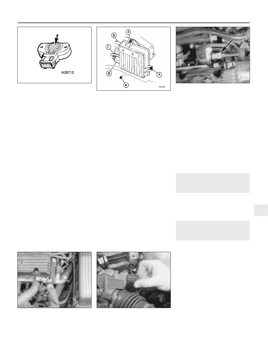
41 Refitting is the reverse of the removal
procedure, noting the following:
a)
Carefully clean the mating surfaces of the
throttle housing and potentiometer.
b)
Refit the potentiometer so that the flat on
the spindle is aligned with the mating
portion of the potentiometer.
c)
When pressing the potentiometer onto
the spindle, apply finger pressure only to
the shaded area shown (see illustration).
d)
Rotate the potentiometer anti-clockwise
only to align the fixing holes.
e)
Tighten the potentiometer screws to their
specified torque wrench setting.
f)
Operate the throttle cam 2 or 3 times
and ensure that full travel exists
between the throttle open and closed
positions.
Engine management
(ignition/fuel injection) ECU
42 Remove the battery.
43 Undo the three nuts securing the ECU to
its mounting bracket (see illustration).
44 Unplug the two multiplug connectors from
the ECU.
45 Release the securing clip and pull the
vacuum hose from the ECU.
46 Remove the ECU from the vehicle.
47 Refitting the ECU is the reverse of the
removal procedure. If a new or different ECU
has been fitted, it may take a short while for
full idle control to be restored.
Intake air temperature sensor
48 Disconnect the battery earth lead.
49 Disconnect the sensor multiplug and
unscrew the sensor from the inlet manifold
(see illustration).
50 Refitting is the reverse of the removal
procedure, noting the following:
a)
Thoroughly clean the sensor threads and
mating surfaces.
b)
Tighten the sensor to the specified torque
wrench setting.
Coolant temperature sensor
51 Disconnect the battery earth lead.
52 Either drain the cooling system or be
prepared for some loss of coolant as the
sensor is unscrewed.
53 Disconnect the sensor multiplug (see
illustration).
54 Unscrew the sensor and withdraw it, then
plug the opening to prevent any entry of dirt. If
the cooling system has not been drained,
work quickly to minimise coolant loss.
55 Refitting is the reverse of the removal
procedure, noting the following:
a)
Thoroughly clean the sensor threads and
mating surfaces.
b)
If a sealing washer is fitted, renew it. If no
sealing washer is fitted, apply a smear of
sealant to the sensor threads.
c)
Tighten the sensor to the specified torque
wrench setting.
d)
On completion, replenish the cooling
system.
Accelerator pedal switch
56 Refer to Section 11 in Part A of this
Chapter.
Fuel cut-off inertia switch
57 Refer to Section 15 in Part B of this
Chapter.
Relays
58 Refer to Chapter 12 for further
information.
15 Inlet manifold pre-heater -
operation, removal and
refitting
1 Refer to Section 15 in Part A of this
Chapter. Note that there is no separate
manifold pre-heater temperature switch. The
ECU uses the information sent from the
coolant temperature sensor.
16 Inlet manifold -
removal and refitting
3
Alloy inlet manifold
Removal
1 Disconnect the battery earth lead.
2 Depressurise the fuel system.
3 Disconnect the hose from the fuel filter,
covering the open connections to prevent any
ingress of dirt.
4 Refer to Chapter 1 and drain the cooling
system.
5 Release the securing clip and detach the
throttle housing-to-air cleaner hose from the
throttle housing.
6 Disconnect the stepper motor and throttle
potentiometer multiplugs (see illustration).
7 Disconnect the breather hose from the
throttle housing.
Fuel and exhaust systems - multi-point fuel injection engines 4C•7
14.49 Intake air temperature sensor
multiplug (arrowed)
14.43 ECU connection points
A
Mounting nuts
B
Multiplug connectors
C
Vacuum hose
14.41 When pressing potentiometer onto
spindle, apply finger pressure only to
shaded area
16.6 Disconnecting stepper motor
multiplug
14.53 Coolant temperature sensor
multiplug (arrowed)
4C
1689 Rover 214 & 414 Updated Version 09/97