Rover 214-414. Service Repair Manual - part 7


  Index      Manuals     Rover 214-414. Service Repair Manual


Search            copyright infringement  


Content      ..     5      6      7      8     ..


Rover 214-414. Service Repair Manual - part 7


Torque wrench settings

Nm

lbf ft

Fuel system

Injector housing fuel pipe union nuts  . . . . . . . . . . . . . . . . . . . . . . . . . . .

24

18

Injector housing fuel pipe adaptors  . . . . . . . . . . . . . . . . . . . . . . . . . . . .

24

18

Injector housing screws  . . . . . . . . . . . . . . . . . . . . . . . . . . . . . . . . . . . . .

5

4

Throttle housing retaining nuts  . . . . . . . . . . . . . . . . . . . . . . . . . . . . . . . .

18

13

Fuel system pressure release bolt - models without catalytic converter12 9
Fuel pump retaining nuts  . . . . . . . . . . . . . . . . . . . . . . . . . . . . . . . . . . . .

9

7

Vent valve and hose retaining nuts . . . . . . . . . . . . . . . . . . . . . . . . . . . . .

9

7

ECU retaining nuts  . . . . . . . . . . . . . . . . . . . . . . . . . . . . . . . . . . . . . . . . .

9

7

Intake air temperature sensor . . . . . . . . . . . . . . . . . . . . . . . . . . . . . . . . .

7

5

Coolant temperature sensor  . . . . . . . . . . . . . . . . . . . . . . . . . . . . . . . . . .

15

11

Inlet manifold nuts and bolts  . . . . . . . . . . . . . . . . . . . . . . . . . . . . . . . . .

25

18

Inlet manifold support stay bolts  . . . . . . . . . . . . . . . . . . . . . . . . . . . . . .

25

18

Exhaust system

Oxygen (lambda) sensor . . . . . . . . . . . . . . . . . . . . . . . . . . . . . . . . . . . . .

55

41

Exhaust manifold retaining nuts  . . . . . . . . . . . . . . . . . . . . . . . . . . . . . . .

45

33

Exhaust manifold shroud screws  . . . . . . . . . . . . . . . . . . . . . . . . . . . . . .

6

4

Exhaust system flange nuts:

Manifold-to-front pipe joint  . . . . . . . . . . . . . . . . . . . . . . . . . . . . . . . . .

50

37

All other joints  . . . . . . . . . . . . . . . . . . . . . . . . . . . . . . . . . . . . . . . . . . .

45

33

Exhaust front pipe mounting bolts  . . . . . . . . . . . . . . . . . . . . . . . . . . . . .

15

11

4B•2 Fuel and exhaust systems - single-point fuel injection engines

1689 Rover 214 & 414 Updated Version 09/97

1

General information and
precautions

General information

The fuel system consists of a fuel tank

mounted under the rear of the vehicle with an
electric fuel pump immersed in it, a fuel filter,
fuel feed and return lines and the throttle body
assembly (which incorporates the single fuel
injector and the fuel pressure regulator), as
well as the Engine Management Electronic
Control Unit (ECU) and the various sensors,
electrical components and related wiring. The
ECU fully controls both the ignition system
and the fuel injection system, integrating the
two in a complete engine management
system (see illustration). Refer to Chapter 5
for information on the ignition side of the
system.

The Rover/Motorola Modular Engine

Management System uses ECU-controlled
single-point injection (MEMS-SPi) and the
speed/density method of airflow
measurement. The whole system is best
explained if considered as three sub-systems
which are, the fuel delivery, air metering and
electrical control systems.

The fuel delivery system incorporates the

fuel tank with an electric fuel pump, which is
immersed in a swirl pot to prevent aeration of
the fuel, inside it. When the ignition is
switched on, the pump is supplied with
current via the fuel pump relay, under the
control of the ECU. The pump feeds petrol via
a non-return valve (to prevent fuel draining out
of the system components and back to the
tank when the pump is not working) to the fuel
filter and from the filter to the injector. Fuel
pressure is controlled by the pressure
regulator, which lifts to allow excess fuel to

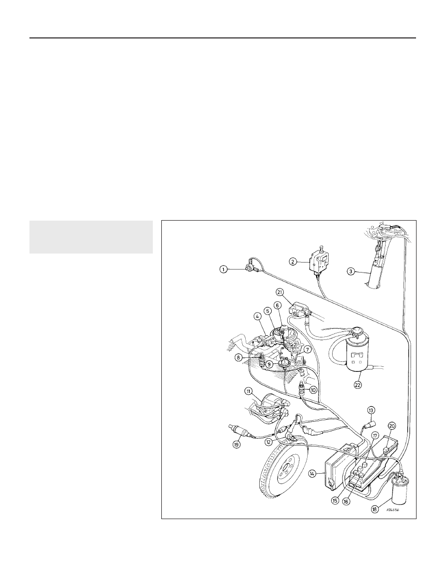
1.0  Fuel and ignition system components - MEMS-SPi

1 Accelerator pedal

switch

2 Fuel cut-out inertia

switch

3 Fuel pump
4 Throttle 

potentiometer

5 Fuel pressure

regulator

6 Injector
7 Stepper motor
8 Intake air temperature

sensor

9 Inlet manifold PTC

heater

10 Coolant 

temperature 
sensor

11 Distributor
12 Crankshaft sensor
13 Diagnostic connector
14 Engine management

ECU

15 Main relay
16 Fuel pump relay
17 Inlet manifold PTC

heater relay

18 Ignition HT coil
19 Lambda sensor -

models 
equipped with
catalytic 
converter

20 Lambda sensor relay -

models equipped with
catalytic converter

21 Purge valve (where

fitted)

22 Charcoal canister

(where fitted)

-------------------------------------------------------------------------------------------------------------------------------------------------------------

return to the tank swirl pot, where a venturi
causes the returning fuel to draw cool fuel
from the tank into the swirl pot. In the event of
sudden deceleration (ie: an accident) an
inertia switch cuts off the power to the pump
so that the risk of fire is minimised from fuel
spraying out of broken fuel lines under
pressure.

The air metering system includes the intake

air temperature control system and the air
cleaner, but the main components are in the
throttle body assembly. This incorporates the
injector, which sprays fuel onto the back of
the throttle disc, the throttle potentiometer,
which is linked to the throttle disc spindle and
sends the ECU information on the rate of
throttle opening by transmitting a varying
voltage, and the stepper motor, which is
controlled by the ECU and operates the
throttle disc spindle lever via a cam and
pushrod to provide idle speed control. Note
that there is no provision for adjustment of the
idle speed except by reprogramming the ECU
using Rover diagnostic equipment. If checking
idle speed, remember that it will vary
constantly under ECU control.

The electrical control system consists of the

ECU, with all the sensors that provide it with
information, and the actuators by which it
controls the whole system’s operation. The
ECU’s manifold absolute pressure sensor is
connected, by hoses and a fuel (vapour) trap
mounted in the air cleaner assembly, to the
inlet manifold. Variations in manifold pressure
are converted into graduated electrical signals
which are used by the ECU to determine the
load on the engine. The intake air temperature
sensor is self-explanatory, the crank-
shaft sensor gives it the engine speed and
crankshaft position, the coolant temperature
sensor gives it the engine temperature and the
accelerator pedal switch tells it when 
the accelerator is closed. The throttle
potentiometer is explained above and the
lambda sensor (where fitted) in Part D of this
Chapter. In addition, the ECU senses battery
voltage (adjusting the injector pulse width to
suit and using the stepper motor to increase
the idle speed and, therefore, the alternator
output if it is too low), incorporates short-
circuit protection and diagnostic capabilities
and can both receive and transmit information

via the diagnostic connector, thus permitting
engine diagnosis and tuning by Rover
diagnostic equipment. If either the coolant
temperature sensor, the intake air
temperature sensor or the manifold absolute
pressure sensor circuits should fail to provide
adequate information, the ECU has a back-up
facility which assumes a value corresponding
to a coolant temperature of 60ºC, an intake air
temperature of 35ºC and an engine load
based on the engine speed and throttle
position. These are used to implement a
back-up air/fuel mixture ratio.

All these signals are compared by the ECU,

using digital techniques, with set values pre-
programmed (mapped) into its memory.
Based on this information, the ECU selects
the response appropriate to those values and
controls the ignition HT coil (varying the
ignition timing as required), the fuel injector
(varying its pulse width - the length of time the
injector is held open - to provide a richer or
weaker mixture, as appropriate), the stepper
motor (controlling the idle and fast idle
speeds), the fuel pump relay (controlling the
fuel delivery), the manifold heater relay
(controlling the inlet manifold pre-heater
system) and the main relay, the purge control
valve (where fitted) and the lambda sensor
and relay (where fitted) accordingly. The
mixture, idle speed and ignition timing are
constantly varied by the ECU to provide the
best settings for cranking, starting and engine
warm-up (with either a hot or cold engine),
idle, cruising and acceleration. A rev-limiter
circuit is built into the ECU which switches off
the injector earth (ie: the fuel supply) if engine
speed exceeds 6860 rpm, switching it back
on at 6820 rpm. The injector earth is also
switched off on the overrun (coolant
temperature above 80ºC, throttle pedal switch
contacts closed, engine speed above
1500 rpm) to improve fuel economy and
reduce exhaust emissions.

The ECU idle control is an adaptive system

which learns the engine load and wear
characteristics over a period of time and
adjusts the idle speed to suit. If the ECU is
renewed, or one from another vehicle is fitted,
it will take a short period of normal driving for

the new ECU to learn the engine’s
characteristics and restore full idle control.

To reduce emissions and to improve

driveability when the engine is cold, the inlet
manifold is heated by the cooling system
coolant and by an electric pre-heater system.
Mixture enrichment for cold starting is a pre-
programmed function of the system.

The air cleaner contains a disposable paper

filter element and incorporates a flap valve air
temperature control system which allows 
cold air from the outside of the vehicle and
warm air from the exhaust manifold to enter
the air cleaner in the correct proportions.

The exhaust system is as described in Part

A of this Chapter.

Precautions

Fuel injection system

Residual pressure will remain in the fuel

lines long after the vehicle was last used,
therefore extra care must be taken when
disconnecting a fuel line hose. Loosen any
fuel hose slowly to avoid a sudden release of
pressure which may cause fuel spray. As an
added precaution, place a rag over each
union as it is disconnected to catch any fuel
which is forcibly expelled.

Fuel usage

Refer to Part A of this Chapter. 

Catalytic converters

Before attempting work on these items,

carefully read the precautions listed in Part D
of this Chapter. 

2

Air cleaner filter element -
renewal

Refer to Chapter 1.

3

Air cleaner assembly -
removal and refitting

2

Removal

Release the two clips securing the air intake
duct to the assembly, then undo the three
screws securing the assembly to the throttle
body (see illustration).
Release the assembly from the intake duct
and withdraw it, collecting the throttle housing
seal and the intake duct sealing ring (where
fitted), then disconnect the following (see
illustration)
:
a)

The thermac switch vacuum pipes. These
are colour-coded (yellow to the
temperature control valve, red to the inlet
manifold).

b)

The ECU manifold absolute pressure
sensor fuel trap vacuum hoses. These are
colour-coded (green to the ECU, white to
the inlet manifold).

c)

The intake air temperature sensor wiring.

Fuel and exhaust systems - single-point fuel injection engines  4B•3

3.2  Thermac switch vacuum pipes (A), fuel

trap vacuum hoses (B), intake air

temperature sensor wiring (C) and throttle

housing seal (D)

3.1  Releasing clips to separate intake duct

from air cleaner

4B

1689 Rover 214 & 414 Updated Version 09/97

-------------------------------------------------------------------------------------------------------------------------------------------------------------

Check the condition of the throttle housing
seal and the intake duct O-ring (where fitted).
Renew either if worn or damaged.
To remove the metal intake duct, refer to
Section 4, paragraphs 3 and 4.
To remove the air intake hose it will first be
necessary to remove the left-hand headlamp
assembly, to gain access to the two retaining
screws. Remove the two retaining screws and
disconnect the duct from the body front
panel, release the clip securing the ignition HT
lead, then slacken the retaining clamp and
unfasten the rubber strap to separate the cold
air duct from the intake duct. Release the
intake hose from the resonator T-piece and
remove it from the engine compartment.
A resonator chamber is fitted to the intake
hose to reduce the amount of induction noise.
To remove the chamber, first remove the
battery and battery tray. Disconnect the intake
hose from the T-piece then remove the
resonator T-piece. Release any relevant
retaining clips from the resonator, then
remove the resonator from the engine
compartment 

(see illustrations).

Refitting

Refitting is the reverse of the removal
procedure. Ensure that the vacuum pipes and
hoses are correctly reconnected and are not
trapped as the assembly is refitted, then
check that the assembly sits properly on the
throttle body before tightening the screws
securely.

4

Air cleaner air temperature
control system 
- inspection
and component renewal

2

Inspection

Refer to Section 4 in Part A of this Chapter.

Thermac switch - renewal

Refer to Section 4 in Part A of this Chapter,
removing the air cleaner assembly as
described in the previous Section.

Air temperature control valve -
renewal

Disconnect the vacuum pipe from the air
temperature control valve, then slacken the
intake hose retaining clamp. Release the
intake hose rubber retaining strap and
disconnect the hose from the metal intake
duct (see illustration).
Release the two clips securing the air intake
duct to the air cleaner assembly and undo the
bolt securing the duct to its mounting bracket
(see illustration). Withdraw the duct, taking
care not to lose the hot air intake connector
hose which connects the duct to the exhaust
manifold shroud.
The air temperature control valve can be
renewed only with the complete intake duct
assembly. If a new intake duct assembly is
being fitted, undo the three screws securing

the hot air intake adaptor plate to the bottom
of the duct and transfer the adaptor plate to
the new duct.
Refitting is the reverse of the removal
procedure.

5

Fuel system - inspection

Refer to Chapter 1.

6

Fuel system -
depressurisation

2

Warning: The following
procedure will merely relieve the
pressure in the fuel system.
Remember that fuel will still be

present in the system components and
take precautions accordingly before
disconnecting any of them.

The fuel system referred to in this Section is
defined as the tank-mounted fuel pump, the
fuel filter, the fuel injector and the pressure
regulator in the injector housing, and the
metal pipes and flexible hoses of the fuel lines
between these components. All these contain
fuel which will be under pressure while the
engine is running and/or while the ignition is
switched on. The pressure will remain for
some time after the ignition has been
switched off and must be relieved before any
of these components are disturbed for
servicing work.

Models with a catalytic
converter

On models equipped with a catalytic
converter, the system is depressurised via the
small bolt fitted to the fuel filter inlet (feed)
union nut.
Position wads of rag around the union to
catch the spilled fuel and slowly slacken the
bolt.
Once all pressure has been released,
remove the bolt. Inspect the sealing washer
for signs of wear or damage and renew if
necessary.
Refit the bolt and sealing washer to the
union nut and tighten it securely.

Models without a catalytic
converter

On models not fitted with a catalytic
converter, the system is depressurised via the
bolt in the metal fuel filter outlet pipe.
Position wads of rag around the pipe to
catch the spilled fuel as the bolt is removed.
Carefully slacken the bolt whilst holding the
fuel pipe boss with an open-ended spanner to

4B•4 Fuel and exhaust systems - single-point fuel injection engines

4.4  Unfastening intake duct-to-support

bracket retaining bolt

4.3  Unfastening cold air intake duct

rubber strap - vacuum pipe (A) and clamp

screw (B)

3.6b  . . . then remove resonator

3.6a  Remove T-piece . . .

1689 Rover 214 & 414 Updated Version 09/97

-------------------------------------------------------------------------------------------------------------------------------------------------------------

prevent any undue strain being placed on the
fuel pipe (see illustration).
Once all pressure has been relieved,
remove the bolt and inspect the sealing
washer for signs of wear or damage and
renew if necessary. 
Refit the bolt and washer to the fuel pipe
and tighten it to the specified torque wrench
setting whilst using a spanner to counter-hold
the pipe boss, to prevent the pipe or filter
being damaged.

7

Fuel system - pressure check

The following procedure is based on the
use of the Rover pressure gauge and adaptor
(Service tool numbers 18G 1500 and 
18G 1500/3).
Depressurise the fuel system.
Unscrew the pressure release bolt and
screw in the adaptor, then connect the
pressure gauge.
Turn the engine over on the starter motor.
The pressure should reach the specified

value. Stop cranking the engine and watch the
gauge. The pressure drop in the first minute
should not exceed 0.7 bar.
If the pressure first recorded was too high,
renew the pressure regulator, which means
renewing the complete injector housing
assembly.
If the pressure first recorded was too low or
if it falls too quickly, check the system
carefully for leaks. If no leaks are found, check
the pump by substituting a new one, then
recheck the pressure. If the pressure does not
improve, the fault is in the pressure regulator
and the complete injector housing assembly
must be renewed. If this is the case, it is worth
dismantling the regulator to check that the
fault is not due to its being jammed open with
dirt.

8

Fuel pump 
removal and refitting

3

Removal

Remove the fuel tank.
Release the clips securing the tank vent
hose to the fuel tank breather and fuel cut-off
valve, then disconnect the hose. Undo the
vent hose and valve retaining nuts, then
disconnect the vent valve hose from the fuel
pump and remove the vent hose and valve
assembly from the tank (see illustration).
Disconnect the wiring connector from the
fuel pump.
Slacken and remove the six fuel pump
retaining nuts. Carefully withdraw the fuel
pump assembly from the tank and remove 
the pump seal.

Refitting

Refitting is a reversal of the removal
sequence, noting the following:

a)

Renew the pump seal if there is any doubt
as to its condition.

b)

Tighten all retaining nuts to the specified
torque setting.

c)

Ensure that the vent hoses are correctly
connected and are securely held by any
necessary retaining clips.

9

Fuel gauge sender unit -
removal and refitting

Refer to Section 7 in Part A of this Chapter.

10 Fuel tank 

removal and refitting

Refer to Section 8 in Part A of this Chapter.
Note that the fuel system must be
depressurised before any fuel hose is
disconnected.

11 Accelerator cable - removal,

refitting and adjustment

2

Removal

Remove the four windscreen wiper motor
mounting bolts to free the motor from the
engine compartment bulkhead.
Slacken the accelerator cable locknuts and
free the cable outer from its mounting bracket.
Release the cable inner from the throttle cam
(see illustration).
Work back along the cable outer and
release it from any retaining clamps.
Working inside the vehicle, undo the five
right-hand lower facia panel retaining screws
and remove the panel.
Release the cable from the upper end of the
accelerator pedal and withdraw the cable
from the engine compartment.

Refitting

Refitting is the reverse of the removal
procedure. Tighten the windscreen wiper
motor retaining bolts to the specified torque

Fuel and exhaust systems - single-point fuel injection engines  4B•5

6.7  Slackening pressure release bolt to
depressurise fuel system - non-catalyst

system

11.2  Disconnecting accelerator cable from

throttle cam pulley

8.2  Fuel pump connections

4B

1689 Rover 214 & 414 Updated Version 09/97

3 Tank vent hose
4 Vent pipe nuts
5 Vent valve nut
6 Cut-off valve hose
7 Pump multiplug
8 Pump housing nuts
9 Pump housing seal

-------------------------------------------------------------------------------------------------------------------------------------------------------------

(Chapter 12) and prior to tightening the cable
locknuts, adjust the cable as follows.

Adjustment

With the pedal fully released, check that
there is equal clearance on each side of the
throttle lever at the lost motion link (see
illustration) 
and no slack in the cable. Have
an assistant fully depress the pedal and check
that the throttle cam opens fully, then check
that it returns to the at-rest position when
released.
To adjust the cable, switch on the ignition
and position the stepper motor by moving the
cam only to open, and fully close the throttle.
Note that it is essential for accurate
positioning of the stepper motor that the
accelerator pedal switch contacts remain
closed, so that the ECU recognises the
throttle movement as a command and
indexes the stepper motor to 25 steps.
Slacken the adjuster locknut (upper nut),
then tighten the adjuster (lower) nut until the
clearance is equal on each side of the throttle

lever at the lost motion link. Tighten the
locknut without disturbing this setting.
Recheck the adjustment and switch off the
ignition.

12 Accelerator pedal 

removal and refitting

Refer to Section 10 in Part A of this Chapter.

13 Throttle housing 

removal and refitting

2

Removal

Depressurise the fuel system.
Disconnect the battery negative terminal
and remove the air cleaner assembly.
Examine the injector housing fuel pipe feed
and return unions for signs of leakage, then
wipe them clean.
Using a spanner to hold each adaptor,
unscrew the pipe union nuts and release the
fuel feed and return pipes from the adaptors.
Plug each pipe and adaptor to minimise the
loss of fuel and prevent the entry of dirt into
the system.
Release the wire retaining clips then
disconnect the wiring connectors from the
injector housing, the throttle potentiometer
and the stepper motor.
Slacken the accelerator cable locknuts and
free the cable outer from its mounting bracket.
Release the cable inner from the throttle cam.
Using a suitable pair of pliers, release the
retaining clips and disconnect the breather
hoses from the throttle housing (see
illustration)
.
Slacken and remove the four nuts securing
the throttle housing to the inlet manifold, then
remove the throttle housing from the vehicle.
Remove the throttle housing insulating spacer
and examine it for signs of wear or damage,
renewing it if necessary (see illustrations).
If leakage was detected from the feed and
return pipes or their union nuts, check the
sealing surfaces of the nuts and adaptors and

renew the adaptor or the pipe assembly, as
necessary.
10 If leakage is detected from the adaptors,
unscrew each through one turn with a
spanner, then through two turns by hand. If
the adaptor is still a tight fit in the housing, the
threads are damaged and the housing and
adaptors must be renewed as a set. If the
threads are sound, fit new sealing washers to
the adaptors and refit them, tightening them
to their specified torque wrench setting.

Refitting

11 Refitting is a reverse of the removal
sequence, noting the following:
a)

Ensure that the mating surfaces of the
throttle housing and inlet manifold are
clean then fit the insulating spacer.

b)

Tighten the throttle housing and fuel pipe
union nuts to their specified torque
settings.

c)

On completion, reconnect and adjust the
accelerator cable.

14 Fuel injection system

components - testing

5

If a fault appears in the engine management
(ignition/fuel injection) system, first ensure
that the fault is not due to poor maintenance.
That is, check that the air cleaner filter
element is clean, the spark plugs are in good
condition and correctly gapped, and that the
engine breather hoses are clear and
undamaged. Also check that the throttle cable
is correctly adjusted. If the engine is running
very roughly, check its compression
pressures, bearing in mind that possibly one
of the hydraulic tappets might be faulty,
producing an incorrect valve clearance.
If these checks fail to reveal the cause of
the problem, the vehicle should be taken to a
suitably-equipped Rover dealer for testing. A
wiring block connector is incorporated in the
engine management circuit into which a
special electronic diagnostic tester can be
plugged. The tester will locate the fault quickly
and simply, thereby alleviating the need to
test all the system components individually

4B•6 Fuel and exhaust systems - single-point fuel injection engines

13.8b  . . . and remove throttle body gasket

spacer

13.8a  Lift throttle body assembly away

from inlet manifold . . .

13.7  Disconnecting breather hoses from

throttle housing

1689 Rover 214 & 414 Updated Version 09/97

11.7  Accelerator cable adjustment

1

Throttle lever to lost motion link clearance
should be equal on each side

2

Adjuster nut

3

Adjuster locknut

-------------------------------------------------------------------------------------------------------------------------------------------------------------

which is a time consuming operation that
carries a high risk of damaging the ECU.
If necessary, the system wiring and wiring
connectors can be checked as described in
Chapter 12. Ensure that the ECU wiring
connectors have first been disconnected.

15 Fuel injection system

components - removal and
refitting

3

Injector housing

Removal

Carry out the operations described in
paragraphs 1 to 4 of Section 13 (see
illustration)
.
Release the wire retaining clip and
disconnect the wiring connector from the
injector housing (see illustration).
Remove the four screws securing the
injector housing to the throttle body, then lift
off the injector housing and remove the
gasket (see illustrations).
If leakage was detected from the fuel feed
and/or return pipes, perform the checks
described in paragraph 9 of Section 13.

Refitting

Refitting is a reversal of the removal
procedure, noting the following:

a)

Ensure the injector and throttle housing
mating surfaces are clean, then fit a new
gasket.

b)

Apply thread locking compound (Rover
recommend Loctite Screwlock or Nutlock)
to the threads of the injector housing
screws, then tighten them to the specified
torque.

c)

Tighten the fuel pipe union nuts to the
specified torque setting.

Fuel injector

Removal

Note that as a Rover replacement part, the
injector is available only as part of the injector
housing. Commence removal by
depressurising the fuel system.
Disconnect the battery negative terminal
then remove the air cleaner assembly.
Slacken and remove the injector connector
cap retaining screw and lift off the connector
cap. The injector can then be lifted out of the
housing (see illustrations).

Refitting

Refitting is the reverse of the removal
procedure. Ensure that the connector 
cap makes good contact with the injector
pins.

Fuel pressure regulator

10 The fuel pressure regulator is available

only as part of the injector housing assembly.
Refer to paragraphs 1 to 5 for details on
removal and refitting.

Stepper motor

Removal

11 Remove the injector housing as described
in paragraphs 1 to 4.
12 Release the retaining clip and disconnect
the stepper motor wiring connector (see
illustration)
.
13 Remove the four stepper motor retaining
screws and remove the stepper motor
assembly from the throttle housing (see

Fuel and exhaust systems - single-point fuel injection engines  4B•7

15.3a  Injector housing-to-throttle body

screws (A), connector cap screw (B) and

pressure regulator screws (C)

15.3b  Remove injector housing from

throttle body - noting gasket

15.2  Disconnecting wiring connector from

injector housing

15.1  Disconnecting fuel feed and return

pipes from injector housing

15.12  Disconnecting stepper motor wiring

connector

15.8b  . . . and withdraw injector

15.8a  Remove screw then lift off injector

connector cap . . .

4B

1689 Rover 214 & 414 Updated Version 09/97

-------------------------------------------------------------------------------------------------------------------------------------------------------------

illustrations). Do not attempt to dismantle the
assembly.

Refitting

14 Refitting is the reverse of the removal
procedure. Ensure that the throttle housing
and motor mating surfaces are clean and on
completion, adjust the throttle cable to ensure
that the stepper motor is correctly indexed.

Throttle potentiometer

Removal

15 Although not strictly necessary, access is
greatly improved if the air cleaner assembly is
first removed.

16 Disconnect the battery negative lead.
17 Release the wire retaining clip and
disconnect the potentiometer wiring
connector 

(see illustration).

18 Remove the two screws and remove the
potentiometer from the throttle housing,
noting how its tongue engages with the
throttle disc spindle lever. Withdraw the
spacer if required.

Refitting

19 Refitting is the reverse of the removal
procedure, noting the following (see
illustration)
:
a)

Carefully clean the mating surfaces of the
throttle body, the spacer and the
potentiometer, then refit the spacer.

b)

Refit the potentiometer so that its tongue
engages FORWARD of (ie: inside) the
throttle disc spindle lever, then rotate the
throttle cam to check the action of the
lever and tongue.

c)

Securely tighten the potentiometer
screws then recheck the potentiometer
operation before reconnecting the wiring
connector.

Engine management
(ignition/fuel injection) ECU

Removal

20 Disconnect the battery negative terminal
and unplug the wiring connector(s) from the
ECU (see illustration).

21 Disconnect the absolute pressure sensor
vacuum hose from the unit, then undo the
three retaining nuts and remove the ECU from
the engine compartment (see illustrations).

Refitting

22 Refitting is a reverse of the removal
sequence. Tighten the ECU retaining nuts to
the specified torque. Due to the nature of the
ECU, if a new or different ECU has been fitted,
it may take a short while for full idle control to
be restored.

Manifold absolute pressure
sensor

23 This is part of the ECU and is removed
and refitted as described above.
24 The sensor’s vacuum hose runs from the
inlet manifold to the ECU via a fuel (vapour)
trap mounted in the air cleaner assembly.
25 To remove the fuel trap, remove the air
cleaner assembly cover, release the clips and
disconnect the hoses, then remove the single
retaining screw and withdraw the trap.
26 On refitting, note that the hoses are
colour-coded (green to the ECU, white to the
inlet manifold) to ensure correct reconnection
(see illustration).

Intake air temperature sensor

Removal

27 Disconnect the battery negative lead.

4B•8 Fuel and exhaust systems - single-point fuel injection engines

15.21b  . . . then undo ECU mounting nuts

(arrowed) and remove unit

15.21a  . . . and absolute pressure sensor

vacuum hose from ECU . . .

15.20  Disconnect wiring connector . . .

15.19  Ensure potentiometer tongue

engages correctly with throttle lever

(spacer arrowed)

15.17  Disconnecting throttle

potentiometer wiring connector (mounting

screws arrowed)

15.13b  . . . and remove stepper motor

assembly

15.13a  Undo stepper motor retaining

screws (arrowed) . . .

1689 Rover 214 & 414 Updated Version 09/97

-------------------------------------------------------------------------------------------------------------------------------------------------------------

28 Remove the air cleaner metal intake duct
(see illustration).
29 Release the wire clip and disconnect the
sensor wiring.
30 Unscrew the sensor and remove it from
the air cleaner housing.

Refitting

31 Refitting is the reverse of the removal
procedure. Tighten the sensor to its specified
torque wrench setting.

Coolant temperature sensor

Removal

32 The coolant temperature sensor is fitted
to the underside of the inlet manifold (see
illustration)
. Either drain the cooling system
or be prepared for some loss of coolant as the
sensor is unscrewed.
33 Release the wire retaining clip and
disconnect the wiring connector from the
sensor.
34 Unscrew the sensor from the manifold
and withdraw it, then plug the opening to
prevent the entry of dirt. If the cooling system
has not been drained, work quickly to
minimise coolant loss.

Refitting

35 Wipe clean the threads of the sensor and
of the thermostat housing. If a sealing washer
is fitted, renew it whenever it is disturbed to

prevent leaks. If no sealing washer is fitted,
apply a smear of sealant to the sensor
threads.
36 Refit the sensor, working quickly if the
cooling system was not drained, and tighten it
to the specified torque. Reconnect the wiring
connector.
37 Replenish the cooling system.

Accelerator pedal switch

38 Refer to Section 11 in Part A of this
Chapter.

Fuel cut-off inertia switch

39 The fuel cut-off inertia switch is located
behind the centre console where it is mounted
on the steering column support bracket. If the
switch has tripped, it can be reset by pressing
in the plunger situated at the top of the switch
(see illustration).

Removal

40 Remove the centre console.
41 Disconnect the wiring connector, then
undo the switch mounting bracket retaining
nut and remove the switch (see illustrations).

Refitting

42 Refitting is a reverse of the removal
sequence. Before installing the centre
console, reset the inertia switch by pressing in
the plunger.

Relays

43 Refer to Chapter 12 for further
information.

16 Inlet manifold pre-heater -

operation, removal and
refitting

Refer to Section 15 in Part A of this
Chapter. Note that there is no separate
manifold pre-heater temperature switch. The
ECU uses the information sent from the
coolant temperature sensor (see illustration).

Fuel and exhaust systems - single-point fuel injection engines  4B•9

15.32  Coolant temperature sensor

(arrowed)

15.39  Reset fuel cut-off inertia switch by

depressing plunger

15.28  Remove air cleaner metal intake

duct to gain access to intake air

temperature sensor

15.26  Absolute pressure sensor fuel trap

hoses are colour-coded to ensure correct

refitting

16.1  Inlet manifold partially removed to

show manifold PTC heater and coolant

temperature sensor (arrowed)

15.41b  . . . and remove switch

15.41a  Undo inertia switch retaining 

nut . . .

4B

1689 Rover 214 & 414 Updated Version 09/97

-------------------------------------------------------------------------------------------------------------------------------------------------------------

17 Inlet manifold 

removal and refitting

3

Removal

Remove the throttle housing.
Drain the cooling system.
Slacken the retaining clamps and
disconnect the coolant hoses from the inlet
manifold (see illustration).
Slacken and remove the brake vacuum
servo unit hose union bolt and disconnect the
hose  (see illustration). Discard the hose
union sealing washers which must be
renewed whenever they are disturbed.
Undo the single bolt securing each
manifold support stay to the cylinder
block/crankcase and slacken the bolts which
secure the stays to the inlet manifold.
Make a final check that all the necessary
vacuum hoses have been disconnected from
the manifold then unscrew the nuts and bolts
securing the manifold to the cylinder head.

Manoeuvre the manifold out of the engine
compartment and discard the manifold gasket
(see illustrations).

Refitting

Refitting is the reverse of the removal
procedure, noting the following (see illustration):
a)

Ensure that the manifold and cylinder
head mating surfaces are clean and dry,
then fit a new manifold gasket.

b)

Working in the sequence shown, tighten the
manifold retaining nuts and bolts evenly, to
the specified torque wrench setting.

c)

Ensure all relevant hoses are reconnected to
their original positions and are securely held
(where necessary) by the retaining clips.

d)

Renew the vacuum servo unit vacuum
hose banjo union sealing washers and
tighten the union bolt securely.

e)

On completion, refill the cooling system.

4B•10 Fuel and exhaust systems - single-point fuel injection engines

17.7  Inlet manifold tightening sequence - K16 engine

17.6b  Remove inlet manifold and withdraw gasket

17.6a  Ensure all vacuum pipes and hoses are disconnected

17.4  . . . and brake servo vacuum hose from inlet manifold

17.3  Disconnect coolant hoses (arrowed) . . .

1689 Rover 214 & 414 Updated Version 09/97

-------------------------------------------------------------------------------------------------------------------------------------------------------------

18 Exhaust manifold 

removal and refitting

3

Removal

Disconnect the battery negative lead. Firmly
apply the handbrake then jack up the front of
the vehicle and support it on axle stands.
Remove the air cleaner metal intake duct.
Undo the two bolts securing the duct
mounting bracket to the cylinder head cover
and remove the bracket.
Undo the two bolts securing the upper
radiator mountings to the bonnet platform,
then remove the mountings and tilt the
radiator forward to gain the clearance
necessary to remove the manifold.
Unscrew the nuts securing the exhaust
front pipe to the manifold, then disconnect the
pipe and collect the gasket.
Undo the five nuts securing the exhaust
manifold to the cylinder head, then carefully
manoeuvre the manifold out of the engine
compartment. Remove the manifold gasket
and discard it.
Examine all the exhaust manifold studs for
signs of damage and corrosion. Remove all
traces of corrosion and repair or renew any
damaged studs.

Refitting

Refitting is the reverse of the removal
procedure, noting the following (see
illustration)
:
a)

Ensure that the manifold and cylinder
head sealing faces are clean and flat, then
fit a new manifold gasket.

b)

Working in the sequence shown, tighten
the manifold retaining nuts evenly to the
specified torque wrench setting.

c)

Tighten all other disturbed nuts and bolts
to their specified torque wrench settings
(where given).

19 Exhaust system - inspection,

removal and refitting

Refer to Section 18 in Part A of this
Chapter. Note that on models fitted with a
closed-loop catalytic converter, the lambda
sensor must be removed or its wiring
disconnected whenever the exhaust 
system front pipe is disconnected from the
manifold.

Fuel and exhaust systems - single-point fuel injection engines  4B•11

4B

1689 Rover 214 & 414 Updated Version 09/97

18.7  Exhaust manifold tightening sequence - K16 engine

-------------------------------------------------------------------------------------------------------------------------------------------------------------

1689 Rover 214 & 414 Updated Version 09/97

4C

Chapter 4 Part C
Fuel and exhaust systems - 
multi-point fuel injection engines

Air cleaner assembly - removal and refitting . . . . . . . . . . . . . . . . . . .

3

Air cleaner filter element - renewal  . . . . . . . . . . . . . . . . . . . . . . . . . .

2

Accelerator cable - removal, refitting and adjustment  . . . . . . . . . . . 10
Accelerator pedal - removal and refitting  . . . . . . . . . . . . . . . . . . . . . 11
Exhaust manifold - removal and refitting  . . . . . . . . . . . . . . . . . . . . . 17
Exhaust system - inspection, removal and refitting  . . . . . . . . . . . . . 18
Fuel gauge sender unit - removal and refitting  . . . . . . . . . . . . . . . . .

8

Fuel injection system components - removal and refitting  . . . . . . . . 14
Fuel injection system components - testing  . . . . . . . . . . . . . . . . . . . 13

Fuel pump - removal and refitting  . . . . . . . . . . . . . . . . . . . . . . . . . . .

7

Fuel system - depressurisation  . . . . . . . . . . . . . . . . . . . . . . . . . . . . .

5

Fuel system - inspection  . . . . . . . . . . . . . . . . . . . . . . . . . . . . . . . . . .

4

Fuel system - pressure check  . . . . . . . . . . . . . . . . . . . . . . . . . . . . . .

6

Fuel tank - removal and refitting  . . . . . . . . . . . . . . . . . . . . . . . . . . . .

9

General information and precautions  . . . . . . . . . . . . . . . . . . . . . . . .

1

Inlet manifold pre-heater - operation, removal and refitting  . . . . . . . 15
Inlet manifold - removal and refitting  . . . . . . . . . . . . . . . . . . . . . . . . 16
Throttle housing - removal and refitting  . . . . . . . . . . . . . . . . . . . . . . 12

4C•1

Contents

Specifications

System

Type  . . . . . . . . . . . . . . . . . . . . . . . . . . . . . . . . . . . . . . . . . . . . . . . . . . . .

Rover/Motorola Modular Engine Management System, using ECU-
controlled multi-point injection (MEMS-MPi) and speed/density
method of airflow measurement 

MEMS-MPi system data

Fuel pump type . . . . . . . . . . . . . . . . . . . . . . . . . . . . . . . . . . . . . . . . . . . .

Electric, immersed in fuel tank

Fuel pressure  . . . . . . . . . . . . . . . . . . . . . . . . . . . . . . . . . . . . . . . . . . . . .

3.0 ± 0.2 bar constant

MEMS - ECU assembly:

Alloy inlet manifold  . . . . . . . . . . . . . . . . . . . . . . . . . . . . . . . . . . . . . . .

MNE 101470

Plastic inlet manifold . . . . . . . . . . . . . . . . . . . . . . . . . . . . . . . . . . . . . .

MKC 101730

Injectors  . . . . . . . . . . . . . . . . . . . . . . . . . . . . . . . . . . . . . . . . . . . . . . . . .

MJY 10015

Throttle potentiometer voltage:

Throttle closed  . . . . . . . . . . . . . . . . . . . . . . . . . . . . . . . . . . . . . . . . . .

0 to 1 volt

Throttle open . . . . . . . . . . . . . . . . . . . . . . . . . . . . . . . . . . . . . . . . . . . .

4 to 5 volt

Idle speed - nominal value given for reference purposes only  . . . . . . . .

850 ± 50 rpm

CO level at idle speed — engine at normal operating temperature  . . . .

0.5 %

Recommended fuel

Minimum octane rating  . . . . . . . . . . . . . . . . . . . . . . . . . . . . . . . . . . . . . .

95 RON unleaded (ie: unleaded Premium) only

Torque wrench settings

Nm

lbf ft

Fuel system

ECU mounting bracket nuts  . . . . . . . . . . . . . . . . . . . . . . . . . . . . . . . . . .

9

7

Vent valve-to-fuel tank nut  . . . . . . . . . . . . . . . . . . . . . . . . . . . . . . . . . . .

9

7

Vent pipe-to-fuel tank nuts  . . . . . . . . . . . . . . . . . . . . . . . . . . . . . . . . . . .

9

7

Fuel pump-to-fuel tank nuts  . . . . . . . . . . . . . . . . . . . . . . . . . . . . . . . . . .

9

7

Fuel filter pressure release union  . . . . . . . . . . . . . . . . . . . . . . . . . . . . . .

38

28

Fuel feed hose union-to-body bolts  . . . . . . . . . . . . . . . . . . . . . . . . . . . .

9

7

Fuel feed hose bolts  . . . . . . . . . . . . . . . . . . . . . . . . . . . . . . . . . . . . . . . .

10

7

Fuel rail bolts  . . . . . . . . . . . . . . . . . . . . . . . . . . . . . . . . . . . . . . . . . . . . .

10

7

Fuel rail support bracket bolts - alloy manifold  . . . . . . . . . . . . . . . . . . .

10

7

Intake air temperature sensor . . . . . . . . . . . . . . . . . . . . . . . . . . . . . . . . .

7

5

Coolant temperature sensor   . . . . . . . . . . . . . . . . . . . . . . . . . . . . . . . . .

15

11

Crankshaft sensor bolts  . . . . . . . . . . . . . . . . . . . . . . . . . . . . . . . . . . . . .

6

4

Easy, suitable for
novice with little
experience

Fairly easy, suitable
for beginner with
some experience

Fairly difficult,
suitable for competent
DIY mechanic

Difficult, suitable for
experienced  DIY
mechanic

Very difficult,
suitable for expert DIY
or  professional

Degrees of difficulty

5

4

3

2

1

-------------------------------------------------------------------------------------------------------------------------------------------------------------

Torque wrench settings

Nm

lbf ft

Fuel system (continued)

Throttle housing-to-alloy manifold nuts  . . . . . . . . . . . . . . . . . . . . . . . . .

8

6

Throttle housing-to-plastic manifold bolts  . . . . . . . . . . . . . . . . . . . . . . .

4

3

Throttle potentiometer screws - plastic manifold  . . . . . . . . . . . . . . . . . .

1.5

1.1

Stepper motor screws - plastic manifold  . . . . . . . . . . . . . . . . . . . . . . . .

1.5

1.1

Pressure regulator-to-fuel rail bolts - alloy manifold  . . . . . . . . . . . . . . .

10

8

Pressure release bolt  . . . . . . . . . . . . . . . . . . . . . . . . . . . . . . . . . . . . . . .

12

9

Inlet manifold mounting nuts and bolts  . . . . . . . . . . . . . . . . . . . . . . . . .

25

18

Exhaust system

Oxygen (lambda) sensor . . . . . . . . . . . . . . . . . . . . . . . . . . . . . . . . . . . . .

55

40

Exhaust manifold retaining nuts  . . . . . . . . . . . . . . . . . . . . . . . . . . . . . . .

45

33

Exhaust manifold shroud screws  . . . . . . . . . . . . . . . . . . . . . . . . . . . . . .

6

4

Exhaust system flange nuts:

Manifold-to-front pipe joint  . . . . . . . . . . . . . . . . . . . . . . . . . . . . . . . . .

50

37

All other joints  . . . . . . . . . . . . . . . . . . . . . . . . . . . . . . . . . . . . . . . . . . .

45

33

Exhaust front pipe mounting bolts  . . . . . . . . . . . . . . . . . . . . . . . . . . . . .

15

11

4C•2 Fuel and exhaust systems - multi-point fuel injection engines

1.0  Fuel and ignition system components - MEMS-MPi

2 Fuel cut-out inertia switch
3 Fuel pump
4 Throttle potentiometer
5 Fuel pressure regulator
6 Injectors
7 Stepper motor
8 Intake air temperature

sensor

9 Coolant temperature

sensor

10 Distributor
11 Crankshaft sensor
12 Diagnostic connector
13 Engine management 

ECU

14 Main relay

15 Fuel pump relay
16 Lambda sensor relay
17 Starter relay
18 Ignition HT coil
19 Purge valve
20 Lambda sensor
21 Charcoal canister
22 Fuel temperature sensor

1689 Rover 214 & 414 Updated Version 09/97

1

General information and
precautions

General information

The fuel system comprises a fuel tank

which is mounted under the rear of the vehicle
with an electric fuel pump immersed in it, a
fuel filter, fuel feed and return lines which
service four fuel injectors interlinked by a rail,
as well as the Electronic Control Unit (ECU)
and the various sensors, electrical
components and related wiring which make
up the system as a whole (see illustration).
Inlet manifolds of either alloy or plastic
construction are fitted.

The air cleaner assembly contains a

disposable paper filter element and is
mounted on the side of the battery tray.

To reduce emissions and to improve

driveability when the engine is cold, the inlet
manifold is heated by the coolant. Mixture
enrichment for cold starting is a pre-
programmed function of the system.

The ECU fully controls both the ignition

system and the fuel injection system,
integrating the two in a complete engine
management system (MEMS-MPi). System
operation is similar to that described for the
single-point fuel injection system (MEMS-SPi)
in Part B of this Chapter, any differences
being made clear in the following Sections.
Refer to Chapter 5 for information on the
ignition side of the system and to Chapter 12
for details of the system relays.

The exhaust system consists of four main

components which are the front downpipe,
the catalytic converter, the intermediate pipe
and middle silencer box, and the tailpipe and
main silencer box. The system is suspended
throughout its entire length by rubber
mountings.

Precautions

Fuel injection system

Residual pressure will remain in the fuel

lines long after the vehicle was last used,

-------------------------------------------------------------------------------------------------------------------------------------------------------------

therefore extra care must be taken when
disconnecting a fuel line hose. Loosen any
fuel hose slowly to avoid a sudden release of
pressure which may cause fuel spray. As an
added precaution, place a rag over each
union as it is disconnected to catch any fuel
which is forcibly expelled.

Fuel usage

Refer to Part A of this Chapter. 

Catalytic coverters

Before attempting work on these items,

carefully read the precautions listed in Part D
of this Chapter. 

2

Air cleaner filter element -
renewal

Refer to Chapter 1.

3

Air cleaner assembly -
removal and refitting

2

Removal

For improved access, remove the battery.
Release the two securing clips and detach
the connecting hose from between the throttle
housing and air cleaner (see illustration).
Note that on engines fitted with a plastic inlet
manifold, the hose is secured to the throttle
housing with a spring clip.
Remove the two battery tray-to-air cleaner
securing bolts (see illustration).
Disconnect the HT coil-to-distributor cap
lead at the cap and from its retaining clip on
the air cleaner (see illustration).
Pull the air cleaner assembly free of its
mounting bracket, release it from its inlet
hose, then remove it from the vehicle.

Refitting

Refitting is the reverse of the removal
procedure. Ensure that all rubber mounting
grommets and hoses are free of splits or
perishing and that all hose clips are securely
tightened.

4

Fuel system - inspection

Refer to Chapter 1.

5

Fuel system -
depressurisation

2

Note: The following procedure will merely
relieve pressure in the fuel system. Remember
that fuel will still be present in the system
components and take precautions accordingly
before disconnecting any of them.
The fuel system is defined as the tank-
mounted fuel pump, the fuel filter, the fuel
injectors and the metal pipes and flexible
hoses of the fuel lines between these
components. All these contain fuel which will
be under pressure while the engine is running
and/or while the ignition is switched on. The
pressure will remain for some time after the
ignition has been switched off and must be
relieved before any of these components are
disturbed for servicing work.
The fuel system is depressurised by
loosening the fuel filter pipe union.
Position wads of rag around the union to
catch spilled fuel. Carefully loosen the union
whilst holding the fuel pipe with an open-
ended spanner to prevent any undue strain
being placed upon it (see illustration).
Once all pressure has been released,
retighten the union to the specified torque
setting whilst using a spanner to counter-hold
the pipe.

6

Fuel system - pressure check

Fuel system testing will involve the use of
specialist Rover tools. Consult your Rover
dealer as to the availability of these tools and
refer to Section 7 in Part B of this Chapter and
to the figures given in the Specifications
Section before proceeding.

7

Fuel pump 
removal and refitting

Refer to Section 8 in Part B of this Chapter.

8

Fuel gauge sender unit -
removal and refitting

Refer to Section 9 in Part A of this Chapter.

9

Fuel tank 
removal and refitting

Refer to Section 10 in Part A of this Chapter
but depressurise the fuel system before
disconnecting any of the fuel lines.

10 Accelerator cable - removal,

refitting and adjustment

2

Note: Before proceeding with any adjustment
of the accelerator cable, ensure that it is
correctly routed. Do not attempt to adjust the
cable by means of the throttle stop screw
.

Removal

Detatch the cable adjuster nut from its
abutment bracket and disengage the cable

Fuel and exhaust systems - multi-point fuel injection engines  4C•3

3.4  Releasing HT coil-to-distributor cap

lead from air cleaner

3.3  Removing battery tray-to-air cleaner

securing bolts (arrowed)

3.2  Releasing throttle housing-to-air

cleaner securing clips

5.3  Loosening fuel filter pipe union

4C

1689 Rover 214 & 414 Updated Version 09/97

-------------------------------------------------------------------------------------------------------------------------------------------------------------

end nipple from the throttle cam (see
illustration)
.
On vehicles with an alloy inlet manifold,
release the cable from its retaining clip on the
engine compartment bulkhead (see
illustration)
.
On vehicles with a plastic inlet manifold,
release the cable from its retaining clip on the
manifold.
It may be necessary to remove the
windscreen wiper motor to gain access to
where the cable passes through the bulkhead. 
Release the cable outer from the bulkhead
by turning its retaining clip (see illustration).
Remove the cable inner-to-throttle pedal
securing clip and detach the cable from the
pedal.
Withdraw the cable from the vehicle.

Refitting

Refitting is the reverse of the removal
procedure. Adjust the cable as follows:

Adjustment

Alloy inlet manifold only

Ensure that the throttle potentiometer and
stepper motor are synchronised.
10 Turn the ignition on and wait for 10
seconds before turning the ignition off to

ensure that the stepper motor is in the setting
position. 

Alloy and plastic inlet manifolds

11 Detach the cable adjuster nut from its
abutment bracket and reposition the cable
outer in the bracket.
12 Turn the cable adjuster nut until it just
makes contact with the top of the abutment
bracket.

Alloy inlet manifold only

13 Hold the cam in the “throttle closed”
position and ensure that the screw is in contact
with the stepper motor pin. Turn the cable
adjuster nut until all slack is removed from the
cable inner. Any linkage gap must be removed
without opening the throttle (see illustration).

Plastic inlet manifold only

14 Hold the throttle cam in contact with the
throttle stop screw and turn the cable adjuster
nut until all slack is removed from the cable
inner. This must be achieved without opening
the throttle.

Alloy and plastic inlet manifolds

15 Check that there is no free play in the
cable outer and refit the cable adjuster nut
into its abutment bracket.
16 Operate the throttle pedal, checking that
the throttle opens to its stop.

11 Accelerator pedal 

removal and refitting

Refer to Section 10 in Part A of this Chap-
ter.

12 Throttle housing 

removal and refitting

2

Alloy inlet manifold

Disconnect the battery earth lead.
Release the two securing clips and 
detach the connecting hose from between the
throttle housing and air cleaner (see
illustration)
.
Disconnect the stepper motor and throttle
potentiometer multiplugs.
Disconnect the breather hose from the
throttle housing.
Pull the accelerator cable adjuster nut from
its abutment bracket and release the cable
inner from the throttle cam.
Remove the four nuts securing the throttle
housing to its mounting and remove the
housing from the vehicle.
Refitting is the reverse of the removal
procedure, noting the following:

a)

Thoroughly clean all component parts,
paying particular attention to the mating
surfaces.

b)

Examine the throttle housing mounting 
for splits or damage and renew if
necessary.

c)

Tighten the housing securing nuts to the
specified torque wrench settings.

d)

Check all hose connections are secure.

e)

Check accelerator cable adjustment.

Plastic inlet manifold

Disconnect the battery earth lead.
Release the two securing clips and 

4C•4 Fuel and exhaust systems - multi-point fuel injection engines

12.2  Release hose securing clips (A),

disconnect stepper motor multiplug (B),
throttle potentiometer multiplug (C) and

breather hose (D)

10.13  Turn accelerator cable adjuster 

nut (A) until all slack is removed from cable

inner. Any linkage gap (B) must be

removed without opening throttle

10.5  Release accelerator cable from

bulkhead by turning retaining clip

(arrowed)

10.2  Releasing accelerator cable from

retaining clip on engine compartment

bulkhead

10.1  Remove accelerator cable adjuster

nut from abutment bracket and disengage

cable end nipple from throttle cam

(arrowed)

1689 Rover 214 & 414 Updated Version 09/97

-------------------------------------------------------------------------------------------------------------------------------------------------------------

detach the connecting hose from between the
throttle housing and air cleaner (see
illustration)
.
10 Loosen the stepper motor hose-to-throttle
housing retaining clip and detach the hose
from the housing.
11 Disconnect the multiplug from the throttle
potentiometer.
12 Disconnect the breather hose from the
throttle housing after loosening its retaining
clip. 
13 Pull the accelerator cable adjuster nut
from its abutment bracket and release the
cable inner from the throttle cam.
14 Remove the four bolts securing the
throttle housing to the inlet manifold, detach
the throttle housing from the manifold and
discard the sealing ring.
15 Refitting is the reverse of the removal
procedure, noting the following.
a)

Thoroughly clean all component parts,
paying particular attention to the mating
surfaces.

b)

Fit a new throttle housing sealing ring,
lubricating it with silicone grease.

c)

Tighten the housing securing bolts to the
specified torque wrench settings.

d)

Check all hose connections are secure.

e)

Check accelerator cable adjustment.

13 Fuel injection system

components - testing

Refer to Section 14 in Part B of this Chap-
ter.

14 Fuel injection system

components 
removal and refitting

3

Fuel rail/injectors

Alloy inlet manifold

Disconnect the battery earth lead.
Depressurise the fuel system.
Detach the inlet manifold chamber and
discard the gasket.

Remove the two bolts securing the fuel
feed hose to the fuel rail and release the hose
from the rail, discarding the O-ring (see
illustration)
.
Disconnect the four injector multiplugs.
Release the retaining clip and disconnect
the hose from the fuel pressure regulator.
Remove the two bolts securing the fuel rail
to the inlet manifold.
Pull each injector from its location in the
inlet manifold and remove the fuel rail,
complete with injectors and pressure
regulator, from the vehicle, placing it on a
clean surface. 
Remove and discard the O-ring fitted to the
base of each injector, then cover the exposed
end of each injector to prevent the ingress of
dirt or moisture (see illustration).  
10 To remove the injectors from the fuel rail,
first remove the spring clip which secures
each injector to the rail (see illustration)
Pull each injector from the rail and discard the
O-ring fitted to its upper end. Again, cover the
exposed end of each injector to prevent the
ingress of dirt or moisture.  
11 Refitting of the injectors and rail is the
reverse of the removal procedure, noting the
following:
a)

Thoroughly clean all component parts,
paying particular attention to the mating
surfaces.

b)

Fit new O-rings, lubricating them with
clean fuel. 

c)

Where applicable, tighten all securing
bolts to the specified torque wrench
settings.

Plastic inlet manifold

12 Disconnect the battery earth lead.
13 Depressurise the fuel system.
14 Loosen the throttle housing breather

Fuel and exhaust systems - multi-point fuel injection engines  4C•5

14.4  Fuel rail/injector assembly - alloy inlet manifold

A

Fuel feed hose connection

B

O-ring

C

Injector multiplug (1 of 4)

D

Fuel pressure regulator

E

Fuel rail securing bolts

F

Fuel injector (1 of 4)

G

Fuel rail

14.10  Remove spring clip (A), pull injec-

tor (B) from rail and discard O-ring (C)

14.9  Discard O-ring (arrowed) fitted to

injector base

12.9  Throttle housing assembly - plastic inlet manifold

A

Hose securing clips

B

Stepper motor hose

C

Throttle potentiometer
multiplug

D

Throttle housing breather
hose

E

Throttle cable adjuster

F

Throttle cam

G

Throttle housing securing
bolts (two shown)

4C

1689 Rover 214 & 414 Updated Version 09/97

-------------------------------------------------------------------------------------------------------------------------------------------------------------

hose-to-camshaft cover retaining clip and
detach the hose (see illustration).
15 Disconnect the multiplug from the stepper
motor.
16 Disconnect the inlet manifold breather
hose from the camshaft cover.
17 Disconnect the vacuum pipe from the fuel
pressure regulator.
18 Loosen the retaining clip and disconnect
the fuel return hose from the fuel rail.
19 Remove the two bolts which secure the
fuel feed pipe to the fuel rail and release the
pipe from the rail, discarding the O-ring (see
illustration 14.4).
20 
Disconnect each injector multiplug and
securing clip.
21 Remove the two bolts securing the fuel
rail to the inlet manifold and detach the rail
from the manifold, together with the fuel
pressure regulator.
22 Note that the rail and regulator are
serviced as an assembly and should not be
separated. If unions are to be left
disconnected for any length of time, then plug
them with clean cloth to prevent the ingress of
dirt or moisture into the system.
23 To remove the injectors, pull each one
from its location in the inlet manifold and
discard both of its O-rings. If leaving the
injectors for any length of time, cover their
exposed ends to prevent the ingress of dirt or
moisture.  
24 Refitting of the injectors and rail is the
reverse of the removal procedure, noting the
following:
a)

Thoroughly clean all component parts,
paying particular attention to the mating
surfaces.

b)

Fit new O-rings, lubricating them with
silicone grease. 

c)

Where applicable, tighten all securing
bolts to the specified torque wrench
settings.

Fuel pressure regulator

Alloy inlet manifold

25 The fuel pressure regulator is secured to
the end of the fuel rail by two bolts (see
illustration)

26 With fuel system pressure released and
the fuel hose disconnected from the regulator
(see fuel rail removal above), remove the
securing bolts and detach the regulator from
the rail.
27 Remove the spacer and O-ring,
discarding the O-ring.
28 Refitting the regulator is the reverse of the
removal procedure. Thoroughly clean the
mating surfaces and fit a new O-ring,
lubricating it with clean fuel. 

Plastic inlet manifold

29 The fuel pressure regulator is available
only as part of the fuel rail and should not be
separated from the same.

Stepper motor

Alloy inlet manifold

30 The stepper motor fitted to this type of
manifold is an integral part of the throttle
housing and as a consequence, cannot be
removed.

Plastic inlet manifold

31 Disconnect the multiplug from the stepper
motor (see illustration).
32 Remove the two Torx screws which

secure the motor to the inlet manifold and
remove the motor, discarding its O-ring.
33 Refitting is the reverse of the removal
procedure, noting the following:
a)

Thoroughly clean the mating surfaces.

b)

Fit a new O-ring to the motor, lubricating
it with silicone grease.

c)

Tighten the motor securing bolts to the
specified torque wrench setting.

Throttle potentiometer

Alloy inlet manifold

34 Disconnect the battery earth lead.
35 Disconnect the multiplug from the
potentiometer 

(see illustration).

36 Remove the two securing screws and
detach the potentiometer from the throttle
housing.
37 Refitting is the reverse of the removal
procedure, noting the following:
a)

Thoroughly clean the mating surfaces.

b)

Ensure correct engagement of the
potentiometer before fitting the securing
screws.

Plastic inlet manifold

38 Disconnect the potentiometer multiplug
(see illustration).
39 Remove and discard the two securing
screws and wavewashers and remove the
clamping plate.
40 Pull the potentiometer off the throttle
spindle being carefull not to apply leverage or
twist the potentiometer.

4C•6 Fuel and exhaust systems - multi-point fuel injection engines

14.38  Potentiometer multiplug (arrowed) -

plastic inlet manifold

14.35  Disconnecting potentiometer

multiplug - alloy inlet manifold

14.31  Disconnect stepper motor 

multiplug (A) and remove Torx screws 

(B - one hidden)

14.25  Fuel pressure regulator location -

alloy inlet manifold

1689 Rover 214 & 414 Updated Version 09/97

14.14  Fuel rail/injector components -

plastic inlet manifold

A

Throttle housing breather hose

B

Inlet manifold breather hose

C

Fuel pressure regulator

D

Fuel return hose

E

Fuel rail securing bolt (1 of 2)

F

Fuel injector multiplug (1 of 4)

G

Fuel injecdtor securing clip (1 of 4)

-------------------------------------------------------------------------------------------------------------------------------------------------------------


Content      ..     5      6      7      8     ..