Rover 820, 825, 827. Repair Manual - part 12
be made out of a large nut, with one end
suitably shaped by cutting or filing so that two
projections are left, which will engage with the
collar slots (see illustration).
6 Engage the home-made tool with the
threaded collar slots, then screw two 10 mm
nuts onto the threaded end of the spindle, and
lock them together. Hold these locknuts to
prevent the spindle turning, and unscrew the
threaded collar.
7 Remove the locknuts, home-made tool and
collar, then withdraw the lower bush and
washer.
8 Lift off the spring, then remove the bump-
stop and shock absorber dust cover.
9 Examine the shock absorber for signs of
fluid leakage. Check the spindle for signs of
wear or pitting along its entire length, and
check the shock absorber body for signs of
damage or corrosion. Test the operation of
the shock absorber, while holding it in an
upright position, by moving the spindle
through a full stroke, and then through short
strokes of 50 to 100 mm. In both cases, the
resistance felt should be smooth and
continuous. If the resistance is jerky or
uneven, or if there is any visible sign of wear,
damage or fluid leakage, renewal is
necessary.
10 If any doubt exists about the condition of
the coil spring, remove the spring
compressors and check the spring for
distortion or damage. The spring free length
can only be assessed by comparing it with a
new item, and this should be done if the
spring is suspect. Renew the spring if
necessary, ideally in pairs (both sides).
11 Check the condition of the spring seat
and upper mounting components, and renew
any parts which are suspect.
Reassembly
12 Begin reassembly by refitting the shock
absorber dust cover and bump-stop.
13 Refit the spring compressors, if previously
removed, and place the spring in position on
the shock absorber.
14 Refit the washer, lower bush and threaded
collar. Tighten the collar using the same
procedure as for removal.
15 Refit the spring seat, upper mounting
plate, upper bush and washer. Secure the
upper mounting assembly with the retaining
nut, tightened to the specified torque.
16 Remove the spring compressors, and refit
the spring and shock absorber to the car as
described in Section 5.
7
Front upper suspension arm
- removal and refitting
3
Note: The upper suspension arm incorporates
the steering knuckle upper support
balljoint as a riveted integral assembly. If wear
of the balljoint necessitates renewal, a
complete upper suspension arm must be
obtained.
Removal
1 Apply the handbrake, prise off the front
wheel trim and slacken the wheel nuts. Jack
up the front of the car and support it on axle
stands. Remove the front roadwheel.
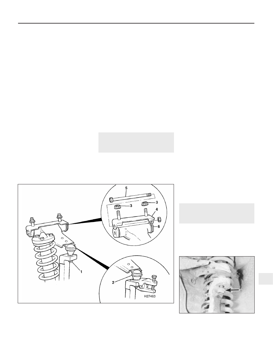
2 Undo the nut securing the upper
suspension arm balljoint to the steering
knuckle (see illustrations). Release the
balljoint using a separator tool or two-legged
puller.
3 From within the engine compartment, undo
the two nuts securing the suspension arm
mounting bracket to the inner wing valance.
For access to the rearmost nut, it may be
necessary to move the wiring harness
connectors aside, or if working on the left-
hand suspension arm, to undo the bolts and
move the wiper motor bracket slightly.
4 Withdraw the upper suspension arm
assembly from under the wheelarch.
5 With the arm on the bench, undo the nut
and withdraw the pivot bolt then remove the
arm from its mounting bracket.
6 Check the condition of the balljoint dust
cover, and check the balljoint for excess free
play. Also check the condition of the pivot
bushes and the arm itself. The bushes can be
renewed by drifting them out then pressing in
new ones. If the balljoint, balljoint dust cover
or the suspension arm show signs of damage
or wear, a complete new assembly must be
obtained. Examine the pivot bolt for signs of
wear ridges, and check the mounting bracket
for elongation of the pivot bolt holes. Renew
any components as necessary.
Refitting
7 Refitting is a reversal of removal, but tighten
all nuts and bolts to the specified torque.
8
Front lower suspension arm
- removal and refitting
4
Removal
1 Apply the handbrake, prise off the front
wheel trim and slacken the wheel nuts. Jack
up the front of the car and support it on axle
stands. Remove the front roadwheel.
Suspension and steering systems 10•7
7.2b Undo the nut securing the upper arm
balljoint to the steering knuckle (arrowed)
10
1380 Rover 800 Series Remake
7.2a Upper suspension arm attachment details
1 Balljoint-to-steering knuckle retaining nut
2 Releasing the balljoint with a separator tool
3 Mounting bracket retaining nuts
4 Mounting bracket
5 Pivot bolt
6 Upper suspension arm