Rover 820, 825, 827. Repair Manual - part 10
4 Undo the three screws and lift off the
control box upper cover.
5 Release the wiring multiplugs from the
mounting brackets on the front of the control
box and disconnect them (see illustration).
Note their connections for refitting.
6 Remove the control box lower cover from
the valve plate assembly.
7 Undo the two screws securing the ignition
timing adjuster to the valve plate and
withdraw the adjuster from its location.
Refitting
8 Refitting is a reversal of removal. On non-
catalyst equipped engines, adjust the ignition
timing as described in Section 10 on
completion.
10 Ignition timing - adjustment
3
General
1 The ignition timing is only adjustable on
non-catalyst equipped V6 engines; on all
other engines, ignition timing is controlled
entirely by the fuel or ignition system ECU.
2 All the following adjustments require the
use of a stroboscopic timing light.
Additionally, if the adjustment is being carried
out on 2.5 litre engines to allow the use of
unleaded fuel, the timing light will need to be
of the adjustable type which allows the unit to
be pre-set to the actual ignition timing value.
This is necessary because the timing marks
provided on the crankshaft pulley are only
applicable to leaded fuel adjustment.
However, by using an adjustable timing light,
the TDC mark on the pulley can be used
instead.
2.5 litre engines
Adjustment for use with leaded fuel
3 Remove the access cover under the right-
hand wheelarch.
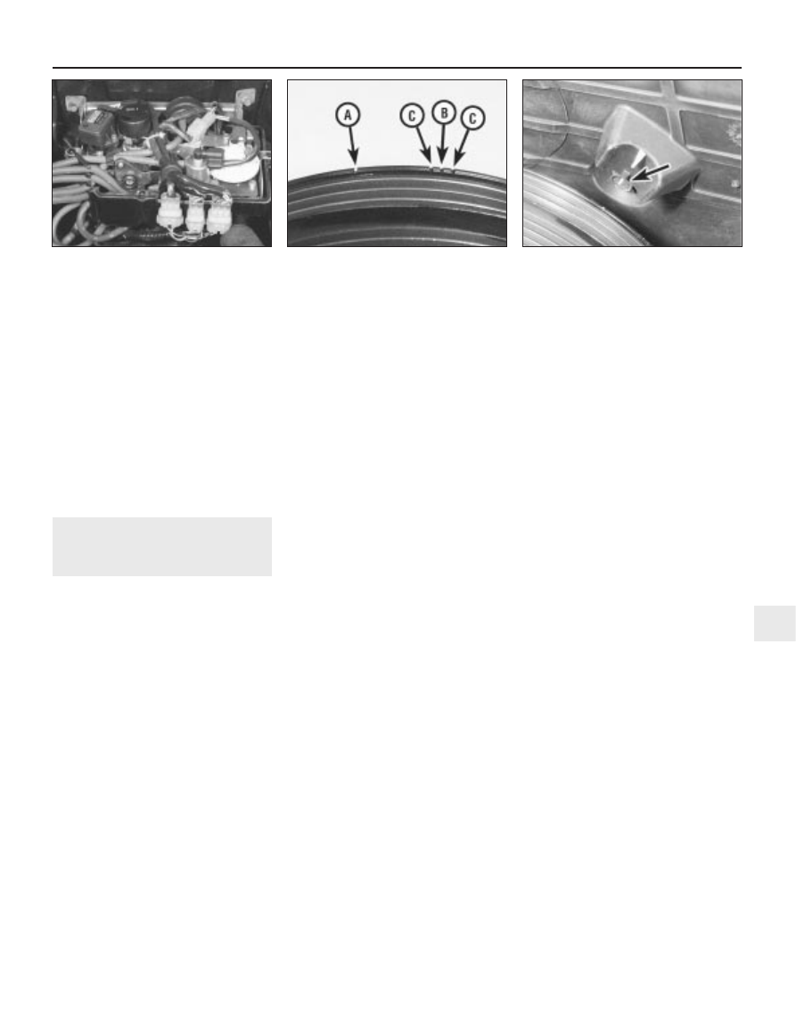
4 Using a socket and bar on the crankshaft
pulley bolt, rotate the crankshaft pulley, in the
normal direction of rotation, until the timing
marks are visible. Note that the timing marks
are four very small notches on the pulley inner
rim and are easily missed. The first notch
(usually coloured white) represents Top Dead
Centre (TDC) for No 1 piston on compression.
The next three notches are the actual timing
marks. The centre notch of the three
represents 13º BTDC (manual transmission) or
11º BTDC (automatic transmission). The
remaining two notches represent a timing
tolerance of ± 2º (see illustration).
5 Once the marks have been located, it is a
good idea to highlight them, and the pointer
on the timing belt cover, with a dab of quick-
drying white paint to make them easily
recognisable when using the timing light (see
illustration).
6 Start the engine and allow it to warm up to
normal operating temperature. Check that the
idling speed is correct and, if necessary,
adjust it as described in Chapter 1.
7 Switch the engine off and connect the
timing light to No 1 cylinder plug lead as
described in the timing light manufacturer’s
instructions. No 1 cylinder is on the rearmost
cylinder at the crankshaft pulley end (beneath
the brake master cylinder).
8 Start the engine again and allow it to idle.
Point the timing light at the timing marks. The
pointer on the timing belt cover should be
aligned with the appropriate notch on the
crankshaft pulley.
9 If adjustment is required, prise off the
plastic cap from the bolt securing the
distributor to the cylinder head, and slacken
the bolt slightly. Rotate the distributor body
clockwise to advance the timing, or anti-
clockwise to retard it, until the pointer and
pulley notch are aligned. Tighten the
distributor securing bolt, recheck that the
marks are still aligned, then refit the plastic
cap.
10 Switch off the engine and disconnect the
timing light. Refit the access cover under the
wheelarch.
Adjustment for use with unleaded fuel
11 As mentioned at the beginning of this
Section, an adjustable timing light will be
required for this operation.
12 Refer to paragraphs 3, 4 and 5 above and
highlight the TDC notch on the pulley and the
pointer on the timing belt cover. Note that the
other three timing marks are not used in the
following procedure and can be ignored.
13 Start the engine and allow it to warm up to
normal operating temperature. Check that the
idling speed is correct and, if necessary,
adjust it as described in Chapter 1.
14 Switch the engine off and connect the
timing light to No 1 cylinder plug lead as
described in the timing light manufacturer’s
instructions. No 1 cylinder is on the rearmost
cylinder at the crankshaft pulley end (beneath
the brake master cylinder).
15 Refer to the Specifications at the
beginning of this Chapter for the correct
ignition timing setting. Set the timing light to
this figure in accordance with the timing light
manufacturer’s instructions.
16 Start the engine again and allow it to idle.
Point the timing light at the timing marks. The
pointer on the timing belt cover should be
aligned with the TDC notch on the crankshaft
pulley.
17 If adjustment is required, prise off the
plastic cap from the bolt securing the
distributor to the cylinder head and slacken
the bolt slightly. Rotate the distributor body
clockwise to advance the timing, or anti-
clockwise to retard it, until the pointer and
pulley notch are aligned. Tighten the
distributor securing bolt, recheck that the
marks are still aligned, then refit the plastic
cap.
18 Switch off the engine and disconnect the
timing light. Refit the access cover under the
wheelarch.
2.7 litre engines
19 Remove the access cover under the right-
hand wheelarch.
20 Using a socket and bar on the crankshaft
pulley bolt, rotate the crankshaft pulley, in the
normal direction of rotation, until the timing
marks are visible. Note that the timing marks
are four very small notches on the pulley inner
rim and are easily missed. The first notch
(usually coloured white) represents Top Dead
Centre (TDC) for No 1 piston on compression.
The next three notches are the actual timing
Engine electrical systems 5•7
10.5 Highlight the pointer on the timing
cover (arrowed) and the relevant pulley
notch with white paint
10.4 Timing mark identification on the
crankshaft pulley
A TDC notch
B Ignition timing setting notch
C ± 2º tolerance notches
9.5 Wiring multiplug connections on the
front of the control box
5
1380 Rover 800 Series Remake