Rover 820, 825, 827. Repair Manual - part 9
modify these basic values to “fine-tune” the
injector opening times to suit precise
operating conditions. Information on
crankshaft speed and position, coolant
temperature, intake air temperature, ambient
air temperature, manifold pressure,
atmospheric pressure and vehicle speed is
supplied to the ECU by the sensors, to enable
initial injection time to be established.
Additional sensors are used, according to
model and equipment levels, to supply
information on exhaust emissions, air
conditioning system operation, automatic
transmission shift position, etc.
Engine idle speed is also controlled by the
ECU in conjunction with an electronic idle
control valve. This valve changes the amount
of air bypassing into the inlet manifold in
response to sensor information processed by
the ECU. This results in a stabilized idle speed
irrespective of additional loads imposed on
the engine from such sources as the
alternator, power steering pump, automatic
transmission, air conditioning compressor, or
other external factors such as temperature
and altitude. Additionally, a temperature
conscious fast idle control bypass valve is
used to increase the amount of air bypassing
into the inlet manifold during warm-up
conditions.
Should certain elements of the system fail,
the ECU can implement a back-up facility,
allowing the system to operate at reduced
performance until the fault can be rectified.
A self-diagnosis function is also provided
whereby any faults detected by the ECU are
stored in its memory and displayed as codes
by a flashing red LED whenever the ignition is
switched on. A second LED is also provided
to indicate whether the initial (manually set)
idle speed adjustment is correct. Both these
LED’s are located on the front of the ECU and
can be seen by looking under the front of the
driver’s seat.
11 Fuel injection system -
testing and adjustment
4
Testing
1 If a fault appears in the fuel injection system
(indicated by the red LED on the ECU flashing
a series of codes), first ensure that all the
system wiring connectors are securely
connected and free of corrosion. Then ensure
that the fault is not due to poor maintenance;
ie, check that the air cleaner filter element is
clean, the spark plugs are in good condition
and correctly gapped, the cylinder
compression pressures are correct, and that
the engine breather hoses are clear and
undamaged, referring to the relevant Parts
and Sections of this Chapter, and to Chap-
ters 1 and 2 for further information.
2 If these checks fail to reveal the cause of
the problem, the vehicle should be taken to a
suitably equipped Rover dealer for the fault
codes to be interpreted and the fault isolated.
This will alleviate the need to test all the
system components individually, which is a
time-consuming operation that carries an
element of risk of damaging the ECU.
Adjustment
Engine tuning procedure
3 The fuel injection system is such that once
the initial engine idle speed and mixture
settings have been set, they are then
controlled by the system’s ECU for all
operating conditions. Although the settings
should be checked at the recommended
service intervals, it is unlikely that any
adjustment will be needed unless a new
component has been fitted. Note also that the
idle mixture setting can only be adjusted on
early models that are not equipped with a
catalytic converter.
4 Before making any changes to the settings
of the fuel injection system, ensure that the
spark plug gaps are correctly set, the air
cleaner element is clean, there are no leaks in
the exhaust system, and the ignition system is
operating correctly. Ensure that all breather
and vacuum hoses are connected, and that
none are perished or kinked.
5 Check that there is the correct amount of
free play in the accelerator cable, and that the
throttle lever rests against its stop in the
released condition. Adjust the cable as
described in Section 3 if necessary.
6 Temperature effects, and engine and
transmission oil drag, can influence the idle
speed and mixture settings, and it is important
that the following warm-up procedure is
adopted before attempting any adjustments.
7 Drive the car on the road for approximately
two to four miles, dependent on summer or
winter conditions, in a normal manner, without
excessive load, engine speed or road speed.
8 Return the car to the working area, ensure
that the steering is in the straight ahead
position then switch the engine off and
connect a tachometer to the engine in
accordance with the equipment
manufacturer’s instructions. If the mixture
setting is being checked, connect an exhaust
gas analyser (CO meter) in accordance with
the equipment manufacturer’s instructions
also. The analyser should be warmed up,
correctly calibrated and ready for immediate
use. Commence the adjustment procedure
described below immediately.
Idle speed adjustment
9 With the engine idling, check the yellow
LED display on the fuel system ECU, by
looking under the front of the driver’s seat.
The LED is visible through the window on the
ECU case (see illustration). If the LED is not
illuminated, the idle speed is correct
and no adjustment is required. If the LED
is illuminated or blinking, adjustment is
required.
10 Switch off all electrical accessories, and
ensure that they remain switched off
throughout the adjustment procedure.
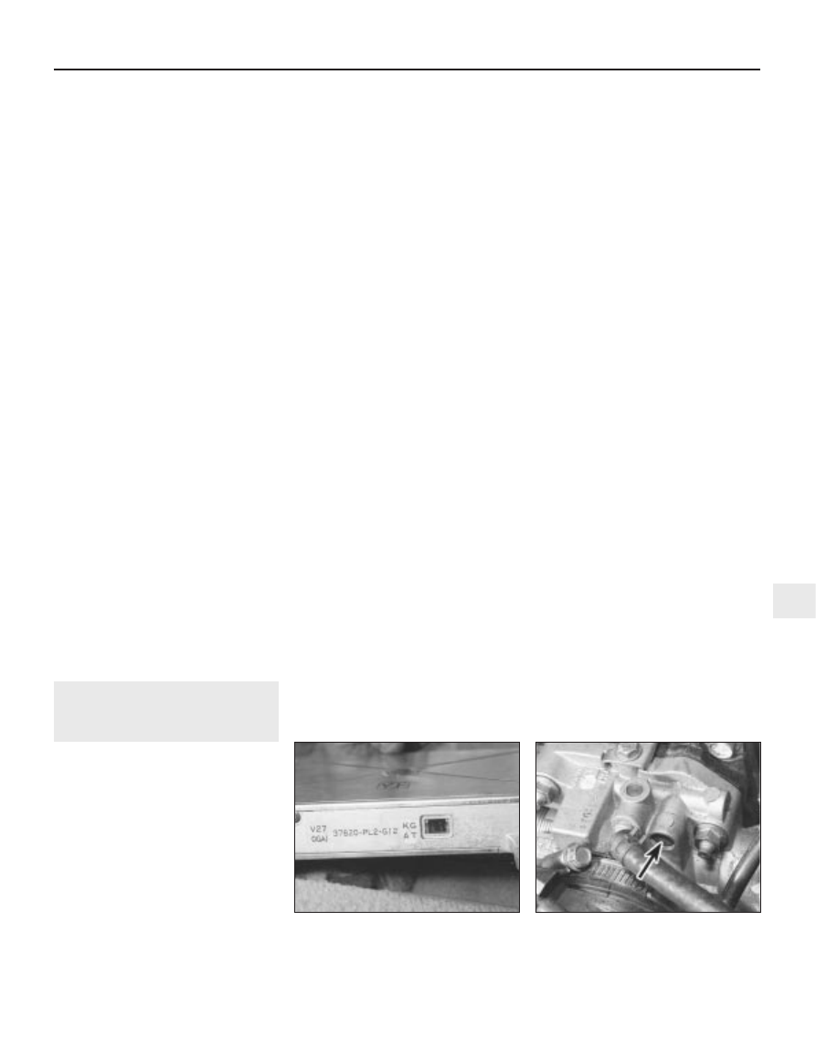
11 If the LED is illuminated constantly (not
blinking), turn the adjustment screw on the
idle valve anti-clockwise to correct the
setting. If the LED is blinking, turn the
adjustment screw clockwise (see
illustration). Always turn the adjustment
screw in 90º increments, and wait thirty
seconds for the idle speed to stabilise.
Check the idling speed on the tachometer
and compare it with the figures given in the
Specifications. Repeat the adjustment until
the setting is correct.
Idle mixture adjustment
12 As mentioned earlier, the idle mixture can
only be adjusted on models without a catalytic
converter.
13 According to model, the idle mixture
adjuster will be located in one of three places:
2.5 litre models - In the control box on the
engine compartment bulkhead (see
illustration).
2.7 litre models - In the control box on the
engine compartment bulkhead, or on the
fuse and relay box in the facia on the
driver’s side, or in front of the fuel system
ECU under the driver’s seat (see
illustrations).
Fuel and exhaust systems - Honda PGM-Fi injection engines 4D•5
11.11 Idle speed adjustment screw
(arrowed) on the idle valve. (On 2.5 litre
engines the screw is on the side of the
valve)
11.9 The ECU viewing window where the
red and yellow LEDs can be seen (driver’s
seat removed for clarity)
4D
1380 Rover 800 Series Remake