MG GS. Service Manual - part 17
 

  Index      Manuals     MG GS. Service Manual


Search            copyright infringement  


Content      ..     15      16      17      18     ..


MG GS. Service Manual - part 17


EMERGENCY INFORMATION

Vehicle Recovery

Towing for Recovery

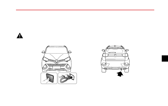
Towing Eye

DO NOT use a tow rope that is twisted - any untwisting force could unscrew the front towing eye.

257

5

-------------------------------------------------------------------------------------------------------------------------------------------------------------

EMERGENCY INFORMATION

Your car is equipped with a removable towing eye, that
can be used at the front or the rear of your vehicle. The
towing eye is stored in the tool kit beneath the loadspace
floor when not in use.

To fit the towing eye, remove the small cover set into the
bumper by pressing firmly on the bottom left corner, then
screw the towing eye into its mounting behind the bumper
(see illustration). Ensure the towing eye is fully tightened.

Note: The towing eye cover may be secured to the
bumper by a plastic cord.

Both towing points are intended for use by qualified
recovery specialists to assist in the recovery of your
car when a breakdown or accident occur. They are not
designed for towing other vehicles, and must NEVER be
used to tow a trailer or caravan.

Towing for Recovery

If, due to an electrical fault, potential safety
hazards may exist, it is not suggested that the
ignition be switched to position II.

When towing, DO NOT suddenly accelerate
or brake suddenly, this can cause accidents.

Suspended Towing

If your car needs to be towed, most qualified recovery
specialists will use wheel lift equipment to suspend the
front wheels, while the rear wheels remain on the ground.

258

-------------------------------------------------------------------------------------------------------------------------------------------------------------

EMERGENCY INFORMATION

Four-Wheel Touchdown Towing

The towing speed of a vehicle with manual
transmission must not exceed 20 mph (30
km/h), the towing distance must not exceed
30 miles 50 km.

The towing speed of a vehicle with dual
clutch automatic transmission must not
exceed 20 mph (30 km/h),

the towing

distance shall not exceed 30 miles (50 km).

If vehicle is towed with the four wheels on the ground,
observe the following precautions:

1 Switch the ignition to position II to enable the brake

lights, wipers and direction indicators to be operated if
necessary. If, due to an electrical fault, it is considered
unsafe to switch the ignition on, the car will need to
be recovered on a trailer.

2 Place the gear shift lever in neutral.

3 Release the hand brake.

Without the engine running, greater effort will be required
to operate the brake pedal and turn the steering wheel.
Longer stopping distances will also be experienced.

259

5

-------------------------------------------------------------------------------------------------------------------------------------------------------------

EMERGENCY INFORMATION

Transporter or Trailer with Rope

If your car is to be transported on the back of a trailer or
transporter, it must be secured as illustrated:

1

1

2

2

2

3

2

2

2

3

Position the car on the trailer, apply the hand brake and
place the gear shift lever in neutral. Fit wheel chocks (1) as
shown, then position the anti slip rubber blocks (2) around
the circumference of the tyre.

Fit the lashing straps (3) around the wheels and secure to
the trailer. Tighten the straps until the car is securely held.

260

-------------------------------------------------------------------------------------------------------------------------------------------------------------

EMERGENCY INFORMATION

Tyre Repair and Wheel Replacement

Tool Identification

*

2

1

3

1 Repair Fluid Reservoir

2 Electric Air Pump

3 Towing Hook

Tyre Repair

*

1 Remove the label at the bottom of the repair fluid

reservoir and attach it to the steering wheel to remind
the driver not to exceed 50 MPH (80 km/h).

8 0
5 0

M a x

k m /h

M a x

m p /h

8 0
5 0

M a x

k m /h

M a x

m p /h

2 Connect the air hose of the electric air pump to

the repair fluid reservoir, fit the tyre sealant bottle
(upright) into the slot on the compressor. Remove
the valve dust cap of the flat tyre, and connect the
filler hose from the tyre sealant bottle to the tyre

261

5

-------------------------------------------------------------------------------------------------------------------------------------------------------------

EMERGENCY INFORMATION

valve. Ensure that the power switch of the electric
air compressor is switched off (i.e., press “O”), then
insert the plug from the compressor into the centre
console power socket.

S T A R T

Note:

To

avoid

battery

discharge,

it

is

recommended to keep the engine running.

3 Switch on the power switch of the electric compressor

(i.e., press “-”), to start pumping sealant into the
tyre. The tyre sealant bottle will become empty after

approximately 30 seconds. The tyre should reach the
specified inflation pressure of 2.3 bar (36 psi) within
5 or 10 minutes.

Note: The pressure gauge may briefly reach 6
bar (87 psi), then the pressure begins to drop to
normal.

4 When the required pressure is reached, switch off the

power switch of the electric compressor (i.e., press
“O”).

Note:

If the required pressure cannot be

reached within 10 minutes, please disconnect the
compressor, drive the vehicle 10 metres (33 feet)
approx forward or backward to allow the sealant
to spread within the tyre. If the required pressure
can still not be reached, the tyre is severely
damaged and you should seek assistance from the
MG Authorised Repairer.

Note:

Consecutive operation of Electric air

compressor for more than 10 minutes may result
in damage to the compressor.

262

-------------------------------------------------------------------------------------------------------------------------------------------------------------

EMERGENCY INFORMATION

Note:

Under no circumstances should you

continue your journey with a deflated tyre.
Driving a vehicle with a deflated tyre is extremely
dangerous.

5 Remove the tyre sealant bottle from the slot in the

compressor, disconnect the hose from the tyre valve,
remove the compressor plug from the centre console
power socket, return the tyre repair kit to its stowage
tray.

6 After successfully adding sealant to the tyre, drive

immediately for a short time (around one minute) this
will allow the sealant to distribute evenly inside the
tyre. Continue driving and do not exceed 50 MPH
(80 km/h).After a further 10 minutes, find a safe place
to stop and recheck the tyre pressure.

• If the tyre pressure has dropped to less than 0.8 bar

(11.6 psi), do not continue driving, seek assistance
instead.

• If the pressure is greater than 0.8 bar (11.6 psi) after

a 10 minutes drive, correct the tyre pressure (see
tyre pressure label) and continue. Check again after
another 10 minute drive. If 1.8 bar (26.1 psi) cannot

be reached, do not continue drive, seek assistance
instead. Do not exceed 50 MPH (80 km/h).

S T A R T

• If the pressure has not dropped after the second 10

minutes drive, continue. If 1.8 bar (26.1 psi) cannot
be reached, do not continue drive, seek assistance
instead. Do not exceed 50 MPH (80 km/h) or 125
miles (200 km).

263

5

-------------------------------------------------------------------------------------------------------------------------------------------------------------

EMERGENCY INFORMATION

Note:

DO

NOT

remove

foreign

objects

(eg.

screws,nails) from the tyre. The tyre repair system
must only be used when the foreign object is in the
tread pattern (A), DO NOT attempt a repair when
the damage is in the sidewall of the tyre (B).

A

B

B

264

-------------------------------------------------------------------------------------------------------------------------------------------------------------

EMERGENCY INFORMATION

Spare Wheel and Tool Kit

*

D

B

A

C

1

2

1 Pull up the luggage cover (1) if any.
2 Lift the luggage carpet handle (2), and fix it in place

to the roof with the attached hook.

3 Unscrew the spare wheel retaining nut (C) and lift

the wheel from the storage space.

4 Remove the tool kit (D).

265

5

-------------------------------------------------------------------------------------------------------------------------------------------------------------

EMERGENCY INFORMATION

Spare Wheel Replacement Tool

3

2

4

5

1

1 Wheel bolt cap removal tool

2 Wheel bolt spanner

3 Towing hook

4 Jack handle

5 Jack

Changing a Wheel

*

If you need to change the wheel during the journey, choose
a safe place to stop away from the main road if possible.
Always ask your passengers to get out of the car and wait
in a safe area away from other traffic.

Switch on hazard warning lamps.

If available, position

a warning triangle about 50 to 150 metres behind your
vehicle to warn approaching traffic.

Before changing a wheel, ensure the front wheels are in the
straight ahead position. Apply the parking brake and place
the gear shift lever of transmission in N position.

Observe the following precautions:

• Ensure the jack is positioned on firm, level ground.

• If the vehicle must be parked on the hill, place chocks

in front of and behind other 3 wheels to prevent the
vehicle moving.

266

-------------------------------------------------------------------------------------------------------------------------------------------------------------

EMERGENCY INFORMATION

Positioning the Jack

NEVER work beneath the car with the jack
as the only means of support. The jack is
designed for wheel changing only!

NEVER jack the car using any jacking points
other than the jacking points.

Serious

damage to the car could result.

Avoid accidental contact with any underbody
parts,

especially

hot

exhaust

system

components.

Position the jack on firm level ground under the jacking
point nearest the wheel to be removed. Note that the
domed head of the jack must fit into the corresponding
recess in the sill plate (see inset in illustration).

Turning the jack screw by hand, adjust the jack until the jack
head fits snugly onto the sill in the correct area. Ensure that
the base of the jack is in full contact with the level ground.

267

5

-------------------------------------------------------------------------------------------------------------------------------------------------------------

EMERGENCY INFORMATION

Fitting the Spare Wheel

Regularly

check

the

spare

wheel

tyre

pressure, it may not be used for long
periods of time. After fitment, at the first
opportunity check and adjust the tyre
pressure.

The wheel bolts must be tightened to the
specified torque after changing a wheel
(120

130 Nm).

1 Before raising the car, use the vehicle tool to remove

each wheel bolt cap. Use the wheel bolt spanner to
slacken each bolt half a turn anti-clockwise.

2 Turn the handle in a clockwise direction until the tyre

is clear of the ground.

3 Remove the wheel bolts and place them in the tool tray

to prevent them from being lost. Make sure the vehicle
is steady and there is no risk of slip or movement
before removing wheel bolts.

4 Remove the road wheel.

Note: Avoid placing wheels face down on the
ground - the surface may be scratched.

5 Fit the spare wheel and tighten the wheel bolts with

wheel bolt spanner until the wheel is seated firmly
against the hub.

6 Lower the car and remove the jack, then FULLY tighten

the wheel bolts in a diagonal sequence.

7 Finally, return the tools to the toolbox, put the toolbox

into the well of the boot floor, tighten the spare wheel
retaining nuts, and put the replaced wheel above the
toolbox in the well in the load space floor (face down).
Lower the boot floor, and put the boot storage box on
the boot floor.

Note: DO NOT stand on the handle of the wheel bolt
spanner or use extension tube on the handle of the
spanner.

Note: When replacing the wheel, please fully tighten
the bolts in the diagonal sequence twice.

268

-------------------------------------------------------------------------------------------------------------------------------------------------------------

EMERGENCY INFORMATION

Note: Note: Consult your MG Authorised Repairer
or tyre specialist for a replacement tyre, as soon as
possible.

Spacesaver Spare Wheel

Only one spacesaver spare wheel can be used
at any one time, otherwise the operational
performance and brake performance may be
reduced, thereby leading to accident or injury
to yourself and others.

When driving on icy or slippery surfaces it is
advised to fit the spacesaver wheel to the rear
of the vehicle to maintain adaquate stability.
This may mean swapping a front wheel with
a rear wheel.

Snow chains can not be used on the
spacesaver spare wheel, this can cause
damage to the car and snow chain.

When the spacesaver spare wheel is fitted, the vehicle
speed should not exceed 50 MPH (80 km/h). Please have
the full-scale tyre repaired and replace the spare wheel as

soon as possible. This will extend the life span of the spare
wheel for other emergencies.

Note: DO NOT use an automatic car wash when
the spacesaver wheel is fitted, the guide rails of the
car wash may conflict with the wheel/tyre and cause
damage.

269

5

-------------------------------------------------------------------------------------------------------------------------------------------------------------

EMERGENCY INFORMATION

Fuse Replacement

Fuse

Fuses are simple circuit breakers which protect the car’s
electrical equipment by preventing the electrical circuits
from being overloaded. A blown fuse may be indicated
when the item of electrical equipment it protect stops
working.

The mounting location and rating of each fuse in engine
compartment fuse box and battery fuse box is shown on
the label printed on the fuse box cover.

If a fuse is suspected faulty, you may remove it from the
fuse box and observe if the metal wire in the fuse is blown.

It is recommended to have spare fuses in the vehicle, which
can be obtained from a local MG authorised repairer.

Comparison before and after the fuse is blown

IMPORTANT

• NEVER attempt to repair a blown fuse. ALWAYS

replace a fuse with one of the same rating.

• If a replaced fuse fails immediately, please contact an

MG Authorised Repairer as soon as possible.

270

-------------------------------------------------------------------------------------------------------------------------------------------------------------

EMERGENCY INFORMATION

Fuse Box

The vehicle is equipped with 3 fuse boxes:

• Battery fuse box (on the battery)

• Passenger compartment fuse box (behind the right

dashboard panel cover)

• Engine compartment fuse box (front left of the engine

compartment)

1

2

3

1 Battery Fuse Box

2 Engine Compartment Fuse Box

3 Passenger Compartment Fuse Box

Battery Fuse Box

F L 2

F U S E  

F L 5

F L 3

F L 4

F U S E 7

Check or Replace a Fuse

1 Turn off the ignition switch and all electrical appliances,

and disconnect the battery negative cable.

2 Press the lock catch (arrowed), remove the upper

cover of battery fuse box.

3 Check if any fuse is blown.

271

5

-------------------------------------------------------------------------------------------------------------------------------------------------------------

EMERGENCY INFORMATION

4 If a fuse is blown, replace it with another fuse of the

same ampere value.

Fuse Specification

Code

Specs

Function

FUSE

FUSE7

5A

Power management DC convertor

FL2

200A

Alternator

FL3

60A

Electronic power assisted steering

FL4

200A

Engine compartment fuse box

FL5

50A

Passenger compartment fuse box

Passenger Compartment Fuse Box

F U S E 1

F U S E 8

F U S E 1 7

F U S E 2 7

F U S E 7

F U S E 1 6

F U S E 2 6

F U S E 3 1

Check or Replace a Fuse

1 Turn off the ignition switch and all electrical appliances,

and disconnect the battery cable.

2 Remove the driver side dashboard panel cover to

access the fuse box.

272

-------------------------------------------------------------------------------------------------------------------------------------------------------------


Content      ..     15      16      17      18     ..