MG 615. Service Manual - part 10


  Index      Manuals     MG 615. Service Manual


Search            copyright infringement  


Content      ..     8      9      10      11     ..


MG 615. Service Manual - part 10


STARTING AND DRIVING

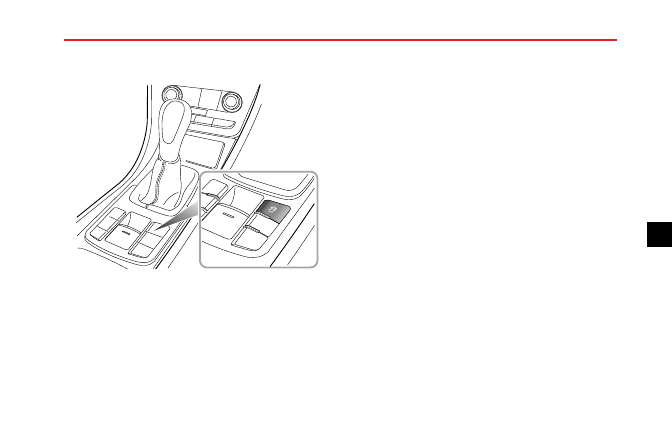
Switching On and Off

O F F

SCS and TCS are automatically on standby after engine
start.

• Briefly press the SCS switch (less than 2 seconds).

TCS is disabled, and the traction control indicator will
illuminate. The Traction Control System Off and the
TCS icon will appear in the message centre.

• Press the SCS switch (more than 2 seconds). TCS and

SCS are both disabled. The traction control System
indicator will illuminate and Traction Control Off
and the TCS icon will appear in the message centre,
followed by the message Stability Control System Off
and the SCS icons displayed.

Note: Activation of the SCS/TCS switch in excess of
10 seconds will be regarded as a mis-operation.

• Briefly press the SCS switch (less than 2 seconds) again,

SCS and TCS will resume, and warning lamps extinguish.

Note: Disabling SCS and TCS will not affect the
operation of ABS. Always disable TC when driving
with snow chains fitted.

SCS/TCS Warning Light

For information on warning light operation, refer to
‘Warning Lights and Indicators’ in ‘Instruments and
Controls’.

145

5

-------------------------------------------------------------------------------------------------------------------------------------------------------------

STARTING AND DRIVING

Tyre Pressure Monitoring System
(TPMS)

The TPMS is not a substitute for checking
tyre condition and pressures.

Note: The TPMS warns of low tyre pressures, it does
not re-inflate the tyres.

System Operation

The system is controlled by the SCS system, which
constantly monitors the speed of each wheel. If, during
normal driving conditions with the brakes not applied,
the SCS detects that one wheel is rotating faster than the
others, it deduces that the pressure of that tyre has fallen
below the predefined limit of the system.

As a result, the warning light on the instrument pack will
illuminate (always yellow).

Check your tyres at the earliest opportunity and reinflate
to the correct pressures. Refer to ‘Tyre Pressures (Cold)’.

Note: When a puncture is detected, the system will
require some time to analise information prior to
illuminating the warning lamp.

System Faults

The system is self monitoring, and if a fault is detected,
the warning light on the instrument pack will flash for 90
seconds and then illuminate (always yellow).

Under certain conditions the warning light may illuminate
when a fault is not present. these conditions include:

• Driving on icy or wet surfaces.

• Front axle slip or excessive lateral acceleration.

• Snow chains fitted.

• A non recommended tyre fitted.

• TPMS not reset after tyre replacement.

• TPMS not reset after tyre pressure adjustment.

• Rough terrain driving for excessive periods.

• Bending or mountain type terrain driving for excessive

periods.

146

-------------------------------------------------------------------------------------------------------------------------------------------------------------

STARTING AND DRIVING

• Excessive luggage weight change from when last reset

carried out.

• TPMS will not respond immediately if a tyre 'blows out'.

Initialising TPMS

If replacement tyres are fitted or tyre pressures changed, a
TPMS reset is required - refer to TPMS reset in Instruments
and Controls.

Note: Inflate tyres to recommended pressures and
check prior to reset.

Note:

Always carry out a TPMS reset after tyre

pressure adjustment.

The TPMS carries out a self

learning process after a reset and therefore may not
react immediately after a reset.

147

5

-------------------------------------------------------------------------------------------------------------------------------------------------------------

STARTING AND DRIVING

Cruise Control

*

S

E

T

R

E S

1

3

2

1 Master switch

2 Thumb wheel

3 Resume (RES) switch

Cruise control enables the driver to maintain a constant
road speed without using the accelerator pedal.

This

is particularly useful for motorway cruising, or for any

journey where a constant speed can be maintained for a
lengthy period.

The following precautions must be observed when using
cruise control:

• DO NOT attempt to use cruise control when using

reverse gear.

• DO NOT use cruise control on winding or slippery road

surfaces, in the rain, or in traffic conditions where a
constant speed cannot easily be maintained.

• ALWAYS switch off the master switch when you no

longer intend to use cruise control.

To Operate Cruise Control

The cruise control system has three switches; two push
switches (master switch and resume switch) and a thumb
wheel set switch. All switches are mounted on the right
hand side of the steering wheel.

1 Press the master switch (1), the warning light in the

instrument pack will illuminate.

2 Accelerate until the desired cruising speed is reached

(this must be above the systems minimum operating
speed of 25MPH).

148

-------------------------------------------------------------------------------------------------------------------------------------------------------------

STARTING AND DRIVING

3 Press the thumb wheel (2) to set the road speed in the

system memory. Cruise control will now maintain that
speed without the need to use the accelerator pedal.

Note: The set speed held in the cruise control memory
will be cancelled when either the cruise control master
switch is pressed or the ignition handset removed.

With cruise control operating, speed can be increased by
normal use of the accelerator e.g. for overtaking. When
the accelerator is released, road speed will return to the
selected cruising speed.

Cruise control will be disengaged when the brake pedal is
pressed or a different gear is selected. To return to your
previous set speed, press the RES switch (3).

Note: Do not operate switches simultaneously or for
long periods, this may result in cruise control failure.
To reset the system cycle the ignition off and on.

To Change the Set Cruising Speed

Rotate the thumb wheel upwards - the car will accelerate
automatically. Release the switch as soon as the desired
speed has been reached.

Rotate the thumb wheel downwards - the car will
decelerate automatically. Release the switch as soon as
the desired speed has been reached.

Alternatively, the set speed can be increased or decreased
incrementally by pushing and releasing the thumb wheel; up
to increase and down to decrease speed. Each operation
of the thumb wheel will increase or decrease the speed by
approximately 1MPH.

149

5

-------------------------------------------------------------------------------------------------------------------------------------------------------------

STARTING AND DRIVING

Intelligent Stop/Start System

Extremely low battery power may result in
the engine not re-starting automatically, or
even using the handset key. In this instance,
external power is needed to start the engine
or the battery will require re-charging. See
the section ‘Emergency Starting’ in the
‘Emergency Information’ Chapter.

1

3

2

1 Instrument indication light

2 Master switch

3 Master switch indication light

Engine Stop/Start has been incorporated into vehicles in
an effort to reduce emissions. As the name suggests the
system will allow the engine to be switched off when engine

150

-------------------------------------------------------------------------------------------------------------------------------------------------------------

STARTING AND DRIVING

power is not required and then automatically be restarted
when it is.

This system defaults “on” at key in, the switch indication
light is on (3 shown in fig ), and can be turned off by pressing
the main switch (2 in the fig- the green “e” symbol shown
above). The Message Centre will show "Stop/Start System
OFF".

Starting the Engine (Initial Start)

• See Section 5, Starting and Driving, but wait for the glow

plug lamp to extinguish in the instrument pack.

Note:

All vehicle functions will work as normal

regardless of the engine running or not.

Engine Auto Stop Conditions (Under Stop

Start Control, warning lamp on, figure 1 in

illustration)

• Vehicle is stationary, i.e. speed = 0MPH or km/h.

• Gearbox must be in Neutral.

• The clutch pedal is released.

• The driver’s door is closed and seat belt is secured.

• The bonnet is closed.

Engine Restart (From Stop/Start Control)

The engine can be restarted by:

• Switching off the system by way of the Stop/Start On/Off

Switch (See 2 on previous page).

• Pressing the clutch pedal.

• Tapping or pressing the accelerator pedal.

• Operating the steering wheel.

• Changing your heater and air-conditioning settings.

The engine will also be started automatically if:

• The brake pedal is pressed repeatedly.

• The battery condition is reduced.

• The vehicle starts to roll.

• The air-conditioning has been operated (under certain

conditions).

Note: In AUTO mode - if the in-car temperature is
lower than target temperature, the ATC controller

151

5

-------------------------------------------------------------------------------------------------------------------------------------------------------------

STARTING AND DRIVING

shall allow the engine to auto-start without any
operation.

Stop/Start Prohibited

Stop Start will not operate if:

• Front defrost is on.

• Heated seats are on and ambient temperature is below

5℃.

• Cabin

temperature

versus

ambient

temperature

difference is more than 5˚C.

• A/C blower speed increased to speed 3 or above in

manual mode.

• Temperature Hi - Hi is selected.

• Temperature Lo - Lo is selected.

• The heater core temperature is less than 60℃.

Stop/Start Operation

Stop Start is controlled or influenced by:

• Stop Start On/Off Switch (See 2 on previous page)

remaining On.

• Gear position – i.e. the vehicle must be in Neutral.

• Battery condition.

• Engine temperature.

• The air conditioning system status.

• The driver’s door is closed and seat belt is secured.

• The bonnet is closed.

• A vehicle speed of 9MPH (15km/h) has been achieved

between stop attempts.

• The gradient upon which the vehicle is sat.

• DPF (Diesel Particulate Filter) regeneration.

152

-------------------------------------------------------------------------------------------------------------------------------------------------------------

STARTING AND DRIVING

Parking Aid System

Ultrasonic Sensor Parking Aid System

*

The purpose of the parking aid is to assist the
driver during parking! The sensors may not
be able to detect certain types of obstruction,
e.g. narrow posts or small objects no more
than a few inches wide, small objects close
to the ground, objects above the level of the
boot and some objects with nonreflective
surfaces.

Keep the sensors free from dirt, ice and snow.
If deposits build up on the surface of the
sensors, their performance may be impaired.
When washing the car, avoid aiming high
pressure water jets directly at the sensors
from close range.

Four ultrasonic sensors, situated in the rear bumper, scan
an area behind the car searching for obstructions. If an
obstruction is detected, the sensors calculate its distance
from the rear of the car and communicate this information

to the driver by sounding warning chimes. It is important
to remember that the system is no more than an AID
to parking. It is not foolproof in operation, nor it is a
substitute for observation and personal judgement.

1 .5 m

3 0 c m

6 0 c m

Parking Aid Operation

With the engine running, the parking aid operates
automatically whenever reverse gear is selected and is
switched off as soon as reverse is disengaged. A short

153

5

-------------------------------------------------------------------------------------------------------------------------------------------------------------

STARTING AND DRIVING

‘beep’ will sound within one second of reverse being
selected to confirm that the system is working.

Note: If a longer, higher pitched, sound is emitted, for
3 seconds when reverse gear is selected, this indicates
a fault with the system - contact MG Authorised
Repairer for assistance.

While Reversing:

• If an obstruction is located within the 1.5 m range of the

rear parking aid sensors or 60 cm of the corner sensors,
the warning commences. As the car moves closer to the
obstruction, the beeps are transmitted more rapidly.

• If an obstruction is located within the 1.2 m range of

the front parking aid sensors or 60 cm of the corner
sensors, the warning commences chiming.

As the

car moves closer to the obstruction, the chimes are
transmitted more rapidly.

• Once the obstruction is within 30 cm of the rear and

front bumper, the chimes merge into a continuous
warning tone.

Rear Parking Camera

*

The rear camera is for guidance only! The
camera range is limited, never rely solely
on the view provided by the camera when
reversing.

Some models have a rear parking camera fitted above the
rear licence plate. When reverse gear is selected, the
camera will display an image of what is immediately behind
the car. This image will be shown on the navigation screen.

154

-------------------------------------------------------------------------------------------------------------------------------------------------------------

STARTING AND DRIVING

Load Carrying

DO NOT exceed the gross vehicle weight
or the permitted front and rear axle loads.
Failure may result in vehicle damage or
serious injury.

Load Space

Ensure that the rear seat backrests are
securely latched in the upright position when
loads are carried in the load space behind
the seats.

If the tailgate can not be closed due to
the type of cargo loaded, be sure to close
all windows during driving, select the face
distribution mode of the air condition, and
set the blower to maximum speed, so as to
decrease exhaust fumes entering the vehicle.

When luggage carried in the load space, always ensure
heavy items are placed as low and as far forward as possible,

so as to avoid the cargo shift in the event of an accident or
sudden stop.

Drive carefully and avoid emergency braking or maneuvers.

Driving with boot/tailgate open is very dangerous.

If

loading with the tailgate open is unavoidable, the cargo and
the tailgate must be well secured, and take appropriate
measures to prevent exhaust fumes entering the vehicle.

IMPORTANT

Traffic regulations must be observed when loading
cargo, if the cargo extrudes the loadspace appropriate
warning measures must be taken to warn other road
users.

Internal Loading

DO NOT carry unsecured equipment, tools
or luggage that could move, causing personal
injury in the event of an accident 

, or

emergency brakes or hard acceleration.

155

5

-------------------------------------------------------------------------------------------------------------------------------------------------------------

STARTING AND DRIVING

Folding the rear seats can increase luggage space, refer to
‘Fold the Rear Seat’ described in the ‘Seats and Restraints’
chapter.

When cargo is loaded in the vehicle, place it at a position
as low as possible and ensure that it is tightly secured, so
as to avoid personal injury caused by cargo movement.

156

-------------------------------------------------------------------------------------------------------------------------------------------------------------

-------------------------------------------------------------------------------------------------------------------------------------------------------------

EMERGENCY INFORMATION

Hazard Warning Devices

Hazard Warning Lights

Before you stop or slow the car in an emergency, always
press the hazard warning switch.

All the direction

indicators will flash together to warn other road users
when your car is causing an obstruction or is in a hazardous
situation. Remember to switch off before driving away.

Warning Triangle

The warning triangle supplied with your car is stowed in
the loadspace.

If you have to stop your car on the road in an emergency,
you must place a warning triangle approximately 50 to 150
metres (150 to 500 ft ) behind the car to warn other road
users of your position.

158

-------------------------------------------------------------------------------------------------------------------------------------------------------------

EMERGENCY INFORMATION

Emergency Starting

Using Booster Cables

NEVER start the engine by pushing or towing.

Make sure that BOTH batteries are of the
same voltage (12 volts), and that the booster
cables are approved for use with 12 volt car
batteries.

Ensure sparks and naked lights are kept well
away from the engine compartment.

Using booster cables (jump leads) from a donor battery,
or a battery fitted to a donor vehicle, is the only approved
method of starting a car with a flat battery.

If the battery from a donor vehicle is to be used, the
vehicles should be parked with their battery locations
adjacent to one another. Ensure that the two vehicles do
not touch.

Starting the Vehicle

Ensure that each booster cable connection is
securely made. There must be no risk of the
clips accidentally slipping from the battery
terminals (as a result of engine vibration, for
example), this could cause sparking, which
could lead to fire or explosion.

A

B

159

6

-------------------------------------------------------------------------------------------------------------------------------------------------------------

EMERGENCY INFORMATION

Remove the ignition handset and switch off ALL electrical
equipment of BOTH vehicles, then follow the instructions
below:

1 Connect the RED booster cable between the positive

( + ) terminals of both batteries.

Connect the

BLACK booster cable from the negative ( - )
terminal of the donor battery (A) to a good earth
point (an engine mounting or other unpainted surface,
for example), at least 0.5 m from the battery and well
away from fuel and brake lines on the disabled vehicle
(B).

IMPORTANT

DO NOT connect a booster cable to the negative
(-) terminal of the discharged battery! This may
result in damage the electrical components.

2 Check that the cables are clear of moving parts of both

engines, then start the engine of the donor vehicle and
allow it to idle for a few minutes.

3 Now start the engine of the vehicle with the

discharged battery (DO NOT crank the engine for
more than 10 seconds).

4 Once both engines are running normally, allow them

to idle for two minutes before switching off the engine
of the donor vehicle and disconnecting the booster
cables.

DO NOT switch on any electrical circuits

on the previously disabled vehicle until AFTER the
booster cables have been removed.

5 Disconnecting the booster cables must be an exact

reversal of the procedure used to connect them,
i.e.disconnect the BLACK cable from the earth point
on the disabled vehicle FIRST.

Battery replacement refers to the section ‘Battery’ in the
‘Maintenance’ Chapter.

IMPORTANT

NEVER turn on any electrical equipment on the
started vehicle before removing the booster cables.

160

-------------------------------------------------------------------------------------------------------------------------------------------------------------


Content      ..     8      9      10      11     ..